ANTI-LOCK BRAKES
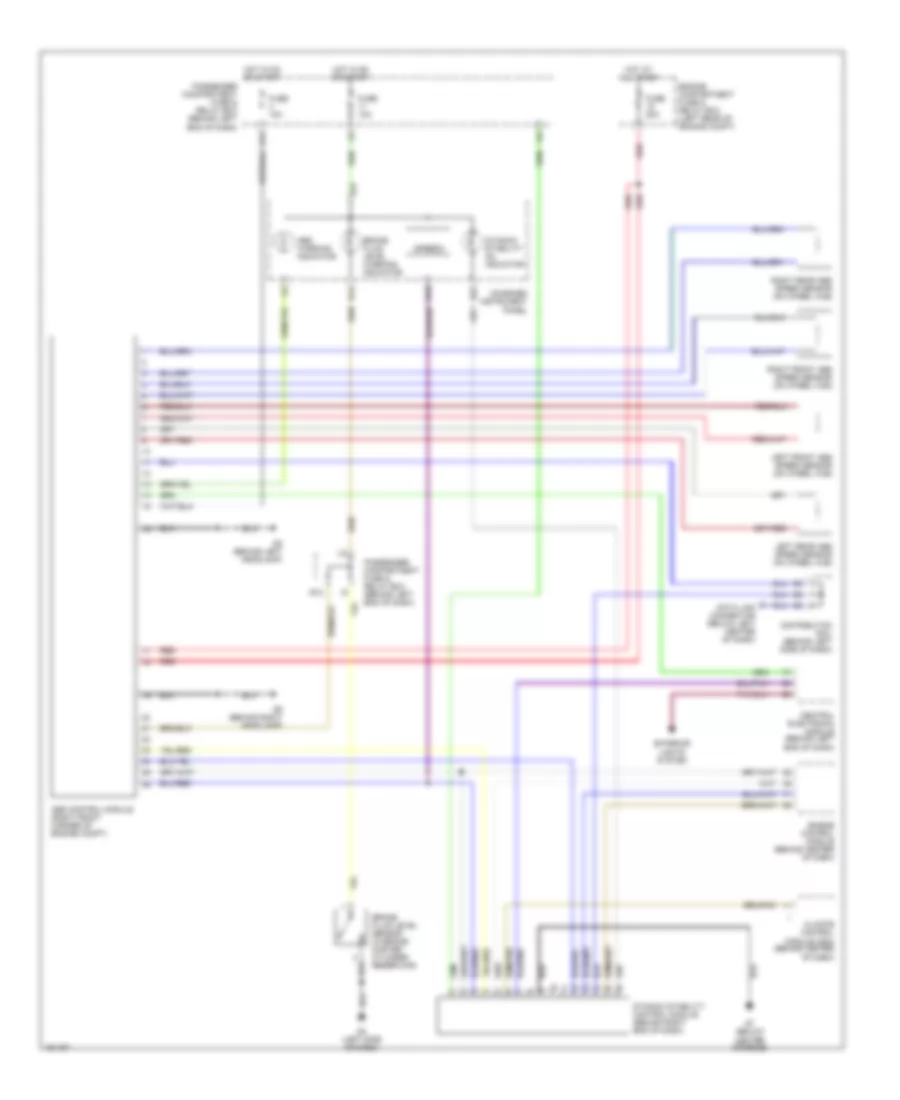
Anti-lock Brakes Wiring Diagram for Volvo V40 2003
List of elements for Anti-lock Brakes Wiring Diagram for Volvo V40 2003:
- A17
- Abs control module (right front corner of engine compt)
- Abs warning indicator
- B14
- B16
- B22
- Brake fluid level sensor (in brake master cylinder reservoir)
- Brake fluid level warning indicator
- Central electronic module (behind left end of dash)
- Climate control module (ccm) (behind center of dash)
- Combined instrument panel
- Data link connector (below left center of dash)
- Distribution rail (behind left side of dash)
- Dynamic stability control module (behind right end of dash)
- Dynamic stability on indicator
- E11
- E12
- Engine compartment fuse & relay box (left rear of engine compt)
- Engine control module (behind center of dash)
- Exterior lights system
- Fuse 10a
- Fuse 50a
- G4 (left side of dash)
- G7 (below center console)
- G8 (behind left headlamp)
- G9 (behind right headlamp)
- Hot at all times
- Hot in on or start
- I10
- I14
- Left front abs speed sensor (on wheel hub)
- Left rear abs speed sensor (on wheel hub)
- Passenger compartment fuse & relay box (behind left end of dash)
- Red
- Right front abs speed sensor (on wheel hub)
- Right rear abs speed sensor (on wheel hub)
- Speedo
 English