ANTI-LOCK BRAKES
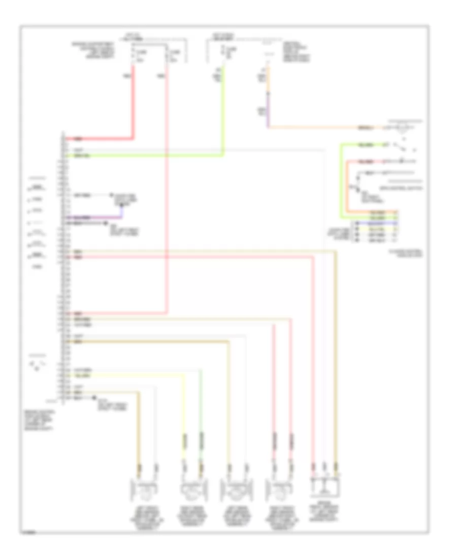
Anti-lock Brakes Wiring Diagram, with Dynamic Stability Control for Volvo V50 T-5 2005

List of elements for Anti-lock Brakes Wiring Diagram, with Dynamic Stability Control for Volvo V50 T-5 2005:
- Body sensor cluster (bsc) (under front passenger's seat)
- Brake control module (bcm) (at left rear corner of engine compt)
- Brake pedal sensor (at left rear corner of engine compt)
- Central electronic module (behind right side of dash)
- Climate control module (ccm)
- Computer data lines system
- Engine compartment distribution box (left side of engine compt)
- Fuse 20a
- Fuse 30a
- Fuse 5a
- G10 (at right kick panel)
- G119 (on left front strut tower)
- G80 (on left front strut tower)
- Hot at all times
- Hot in run or start
- Left front abs sensor (behind left front wheel, on spindle/hub assembly)
- Left rear abs sensor (on left rear spindle/hub assembly)
- Red
- Right front abs sensor (behind right front wheel, on spindle/hub assembly)
- Right rear abs sensor (on right rear spindle/hub assembly)
- Spin control switch
Anti-lock Brakes Wiring Diagram, with Traction Control for Volvo V50 T-5 2005
List of elements for Anti-lock Brakes Wiring Diagram, with Traction Control for Volvo V50 T-5 2005:
- Brake control module (bcm) (at left rear corner of engine compt)
- Brake pedal sensor (at left rear corner of engine compt)
- Central electronic module (behind right side of dash)
- Climate control module (ccm)
- Computer data lines system
- Engine compartment distribution box (left side of engine compt)
- Fuse 20a
- Fuse 30a
- Fuse 5a
- G10 (at right kick panel)
- G119 (on left front strut tower)
- G80 (on left front strut tower)
- Hot at all times
- Hot in run or start
- Left front abs sensor (behind left front wheel, on spindle/hub assembly)
- Left rear abs sensor (on left rear spindle/hub assembly)
- Red
- Right front abs sensor (behind right front wheel, on spindle/hub assembly)
- Right rear abs sensor (on right rear spindle/hub assembly)
- Spin control switch