ANTI-LOCK BRAKES
Anti-lock Brake Wiring Diagrams, with Dynamic Stability Control for Volvo V70 2001

List of elements for Anti-lock Brake Wiring Diagrams, with Dynamic Stability Control for Volvo V70 2001:
- A11
- A12
- A13
- A14
- A37
- A55
- Abs control module (on left rear of engine compt)
- Abs pump motor
- B13
- B17
- B18
- B26
- Brake light contact
- Brake pressure sensor (on brake master cylinder)
- Central electronic module (behind left side of dash)
- Climate control module
- Computer data lines system
- Dstc activation unit (at steering column)
- Engine compartment relay/fuse box (left side of engine compt)
- Engine control module (right side of engine compt)
- Fuse b12 5a
- Fuse b14 30a
- Fuse b19 30a
- Fuse c9 5a
- G104 (rear of left front fender)
- Hot at all times
- Hot in on or start
- Instrument cluster
- Lateral accelerometer (beneath rear of center console)
- Left front abs sensor (on wheel hub)
- Left rear abs sensor (on wheel hub)
- Passenger compartment fuse box (at left end of dash)
- Red
- Right front abs sensor (on wheel hub)
- Right rear abs sensor (on wheel hub)
- Spin control switch
- Yaw angle speed sensor 1 (beneath rear of center console)
- Yaw angle speed sensor 2 (beneath right front seat)
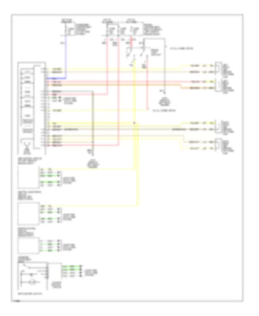
Anti-lock Brake Wiring Diagrams, with Traction Control for Volvo V70 2001
List of elements for Anti-lock Brake Wiring Diagrams, with Traction Control for Volvo V70 2001:
- (w/ all wheel drive)
- A11
- A12
- A13
- A14
- A37
- A55
- Abs control module (on left rear of engine compt)
- Abs pump motor
- B13
- B17
- B18
- B26
- Brake light contact
- C22
- C24
- Central electronic module (behind left side of dash)
- Climate control module
- Combined instrument panel
- Computer data lines system
- Engine compartment relay/fuse box (left side of engine compt)
- Engine control module (right side of engine compt)
- Fuse b12 5a
- Fuse b14 30a
- Fuse b19 30a
- Fuse c9 5a
- G104 (rear of left front fender)
- Hot at all times
- Hot in on or start
- Left front abs sensor (on wheel hub)
- Left rear abs sensor (on wheel hub)
- Passenger compartment fuse box (at left end of dash)
- Red
- Right front abs sensor (on wheel hub)
- Right rear abs sensor (on wheel hub)
- Spin control switch
- Traction control