ANTI-LOCK BRAKES
Anti-lock Brakes Wiring Diagram for Volvo XC70 T-6 2009
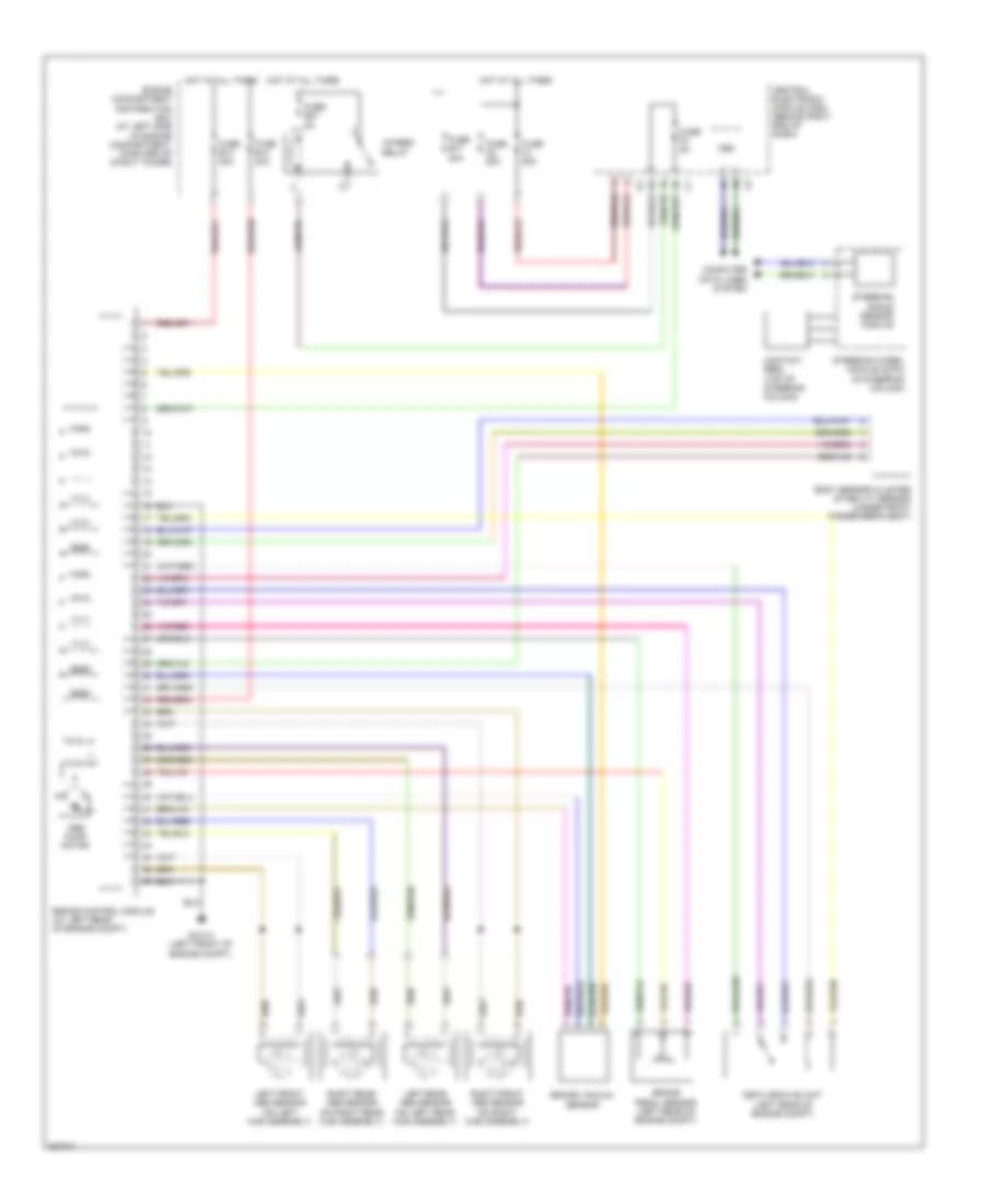
List of elements for Anti-lock Brakes Wiring Diagram for Volvo XC70 T-6 2009:
- (left rear of engine compt)
- 15-feed relay
- Abs pump motor
- Body sensor cluster stability sensor (under front passenger's seat)
- Brake control module (at left rear of engine compt)
- Brake pedal sensor (left rear of engine compt)
- Brake vacuum sensor
- Cem
- Central electronic module (cem) (behind right end of dash)
- Computer data lines system
- Contact reel (top of steering column)
- Dstc archive unit
- Engine compartment distribution box (at left side of engine compartment, forward of strut tower)
- Fuse a1 50a
- Fuse a2 50a
- Fuse b13 40a
- Fuse b14 20a
- Fuse b17 20a
- Fuse b27 5a
- Fuse f3 5a
- Gxx14 (left front of engine compt)
- Hot at all times
- Left front abs sensor (on left hub assembly)
- Left rear abs sensor (on left rear hub assembly)
- Right front abs sensor (on right hub assembly)
- Right rear abs sensor (on right rear hub assembly)
- Steering angle sensor module
- Steering wheel module (swm) (in steering column)
 English