ANTI-THEFT
Forced Entry Wiring Diagram for BMW 540i 1998

List of elements for Forced Entry Wiring Diagram for BMW 540i 1998:
- (driver door sill)
- Anti-theft horn (dwa)
- Computer data lines system
- Driver's door jamb switch
- Fuse f11 7.5a
- Fuse f38 5a
- Fuse f48 5a
- Fuse f53 5a
- Fuse panel 1
- Fuse panel 2
- General module (behind glove compartment)
- Hot at all times
- Hot in acc, run or start
- Interior protection control module
- Left rear door jamb switch
- Liftgate lock switch
- Passenger's door jamb switch
- Right rear door jamb switch
- Tilt sensor
- Underhood light switch
- X10012 (right front footwell)
- X173
- X173 (driver door sill)
- X253
- X254
- X332
- X492 (driver door sill)
- X494 (bottom of right c-pillar)
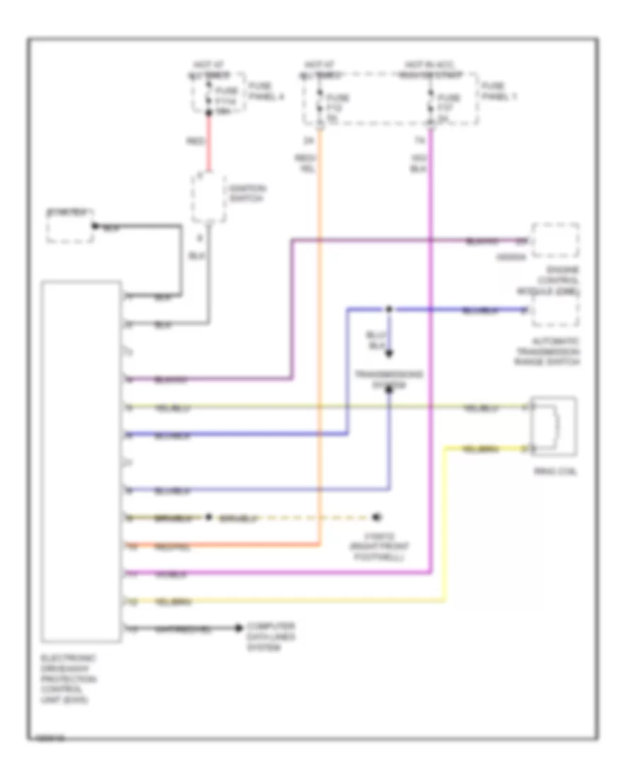
Immobilizer Wiring Diagram for BMW 540i 1998
List of elements for Immobilizer Wiring Diagram for BMW 540i 1998:
- Automatic transmission range switch
- Computer data lines system
- Electronic driveaway protection control unit (ews)
- Engine control module (dme)
- Fuse f114 50a
- Fuse f12 5a
- Fuse f37 5a
- Fuse panel 1
- Fuse panel 4
- Hot at all times
- Hot in acc, run or start
- Ignition switch
- Red
- Ring coil
- Starter
- Transmissions system
- X10012 (right front footwell)
- X60004
 English