ANTI-THEFT
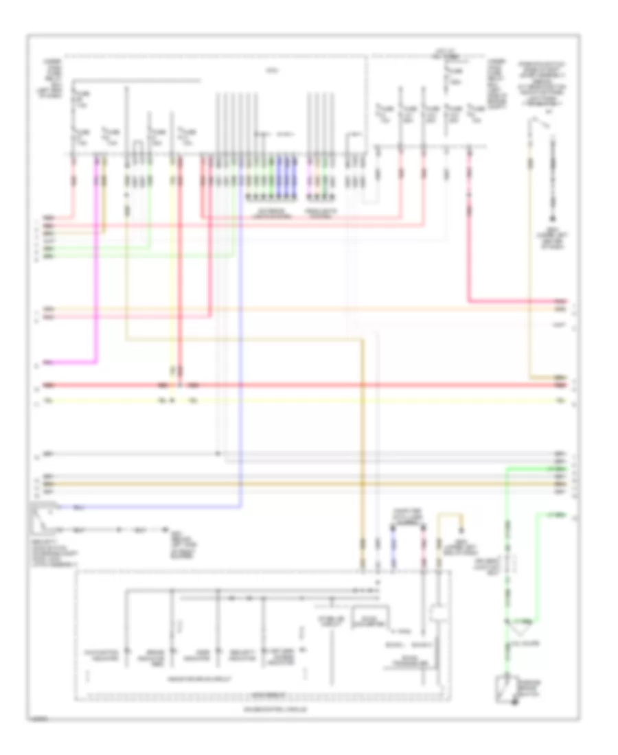
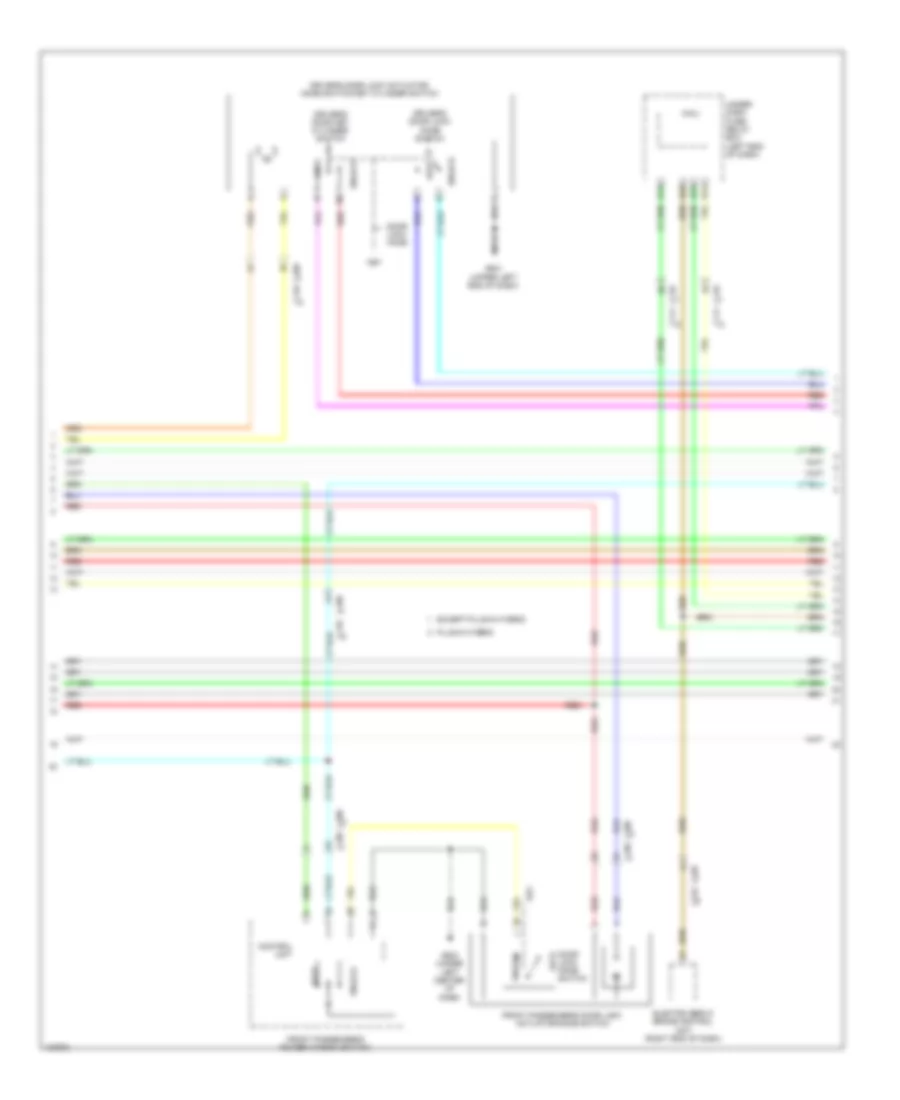
Forced Entry Wiring Diagram, Except Hybrid (1 of 6) for Honda Accord Plug-In 2014

List of elements for Forced Entry Wiring Diagram, Except Hybrid (1 of 6) for Honda Accord Plug-In 2014:
- 2.4l
- 2.4l coupe & 3.5l coupe
- 3.5l
- 3.5l sedan
- A17
- A21
- A27
- A33
- A38
- A49
- A50
- A51
- Accessory sub relay
- C10
- C102
- C106
- C11
- C112
- C12
- C13
- C14
- C15
- C16
- C17
- C18
- C19
- C20
- C21
- C22
- C23
- C24
- Center junction box
- Clutch pedal position switch a (m/t)
- Clutch pedal position switch b (m/t)
- Computer data lines system
- G401 (left kick panel)
- G501 (upper left end of dash)
- G603 (coupe: center rear of luggage compt) (sedan: left rear of luggage compt)
- Ig1a relay
- Ig1b relay
- Ig2 relay
- Keyless access control unit (if equipped) (left side of dash)
- Pcm (2.4l: left side of engine compt) (3.5l: right side of engine compt)
- Pnk
- Red
- Smart buzzer
- Steering lock (on steering column)
- Under-dash sub-relay box
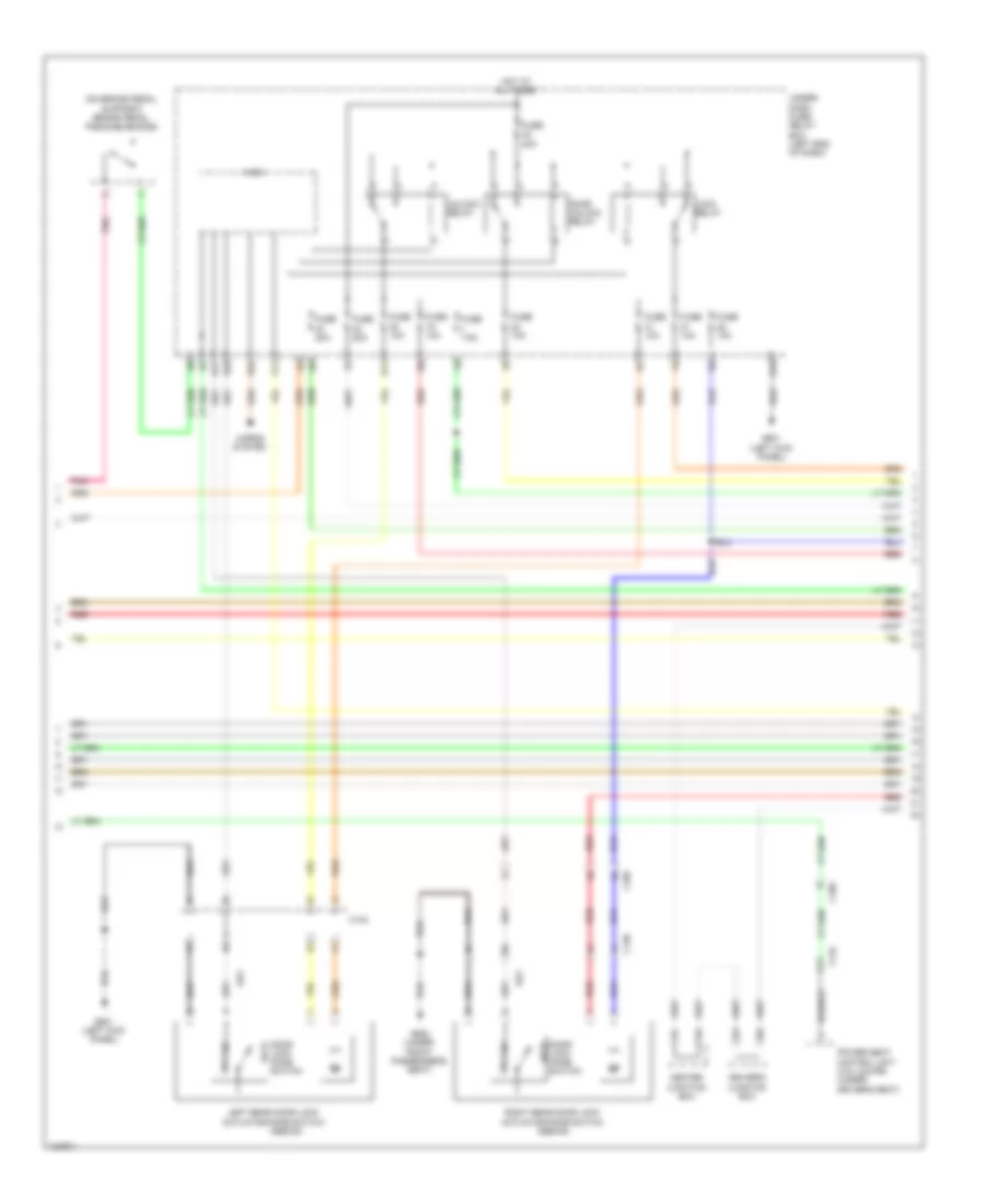
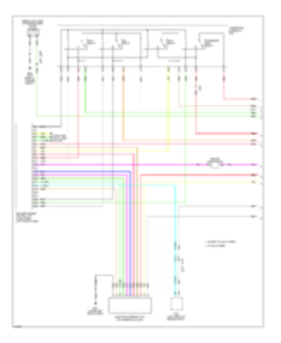
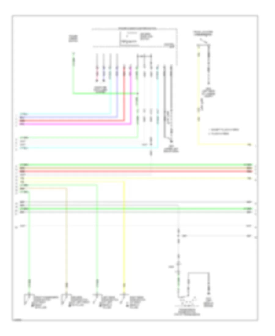
Forced Entry Wiring Diagram, Except Hybrid (2 of 6) for Honda Accord Plug-In 2014
List of elements for Forced Entry Wiring Diagram, Except Hybrid (2 of 6) for Honda Accord Plug-In 2014:
- (park-pin switch: base of shift lever assembly) (sedan) a/t gear position indicator panel light/park- pin switch
- 3.5l coupe
- A17
- A30
- A31
- A32
- B-can h
- B-can l
- B-can transceiver
- Brake indicator (red)
- Computer data lines system
- D20
- D34
- Dc-dc converter
- Door indicator
- Driver's junction box
- E15
- E17
- E23
- E24
- Exterior lights system
- F10
- F12
- Fuse 10a
- Fuse 12-1 60a
- Fuse 12-3 30a
- Fuse 12-4 20a
- Fuse 125a
- Fuse 20a
- Fuse 7.5a
- G301 (behind left side
- G502 (upper left end of dash)
- G503 (under left center of dash)
- Gauge control module
- Headlights system
- Hot at all times
- Indicator drive circuit
- Keyless access indicator
- M10
- M11
- M12
- Main circuit
- Malfunction indicator
- Micu
- Of front bumper)
- P12
- P22
- P24
- Parking brake switch
- Pnk
- Red
- S10
- Security hood switch (on engine compt hood lock/ latch assembly)
- Security indicator
- Stabilize circuit
- T10
- Under- dash fuse/ relay box (left end of dash)
- Under- hood fuse/ relay box (left side of engine compt)
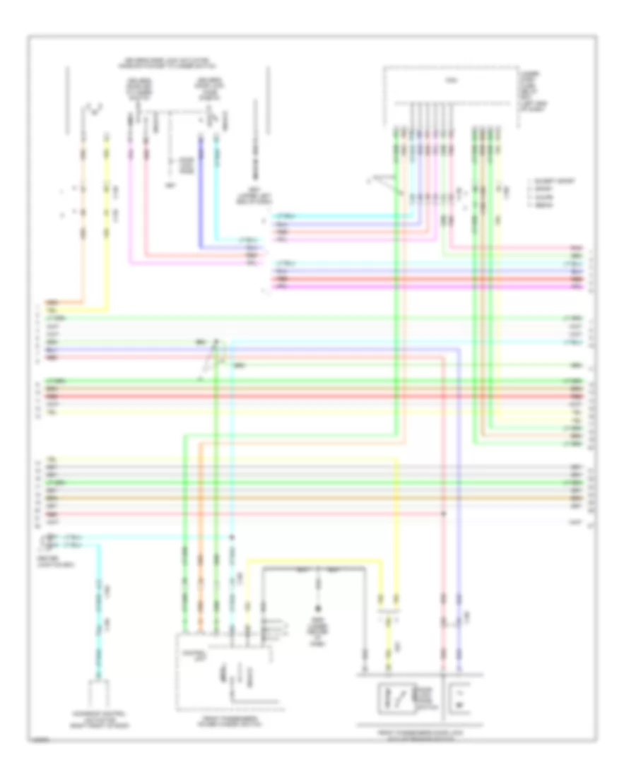
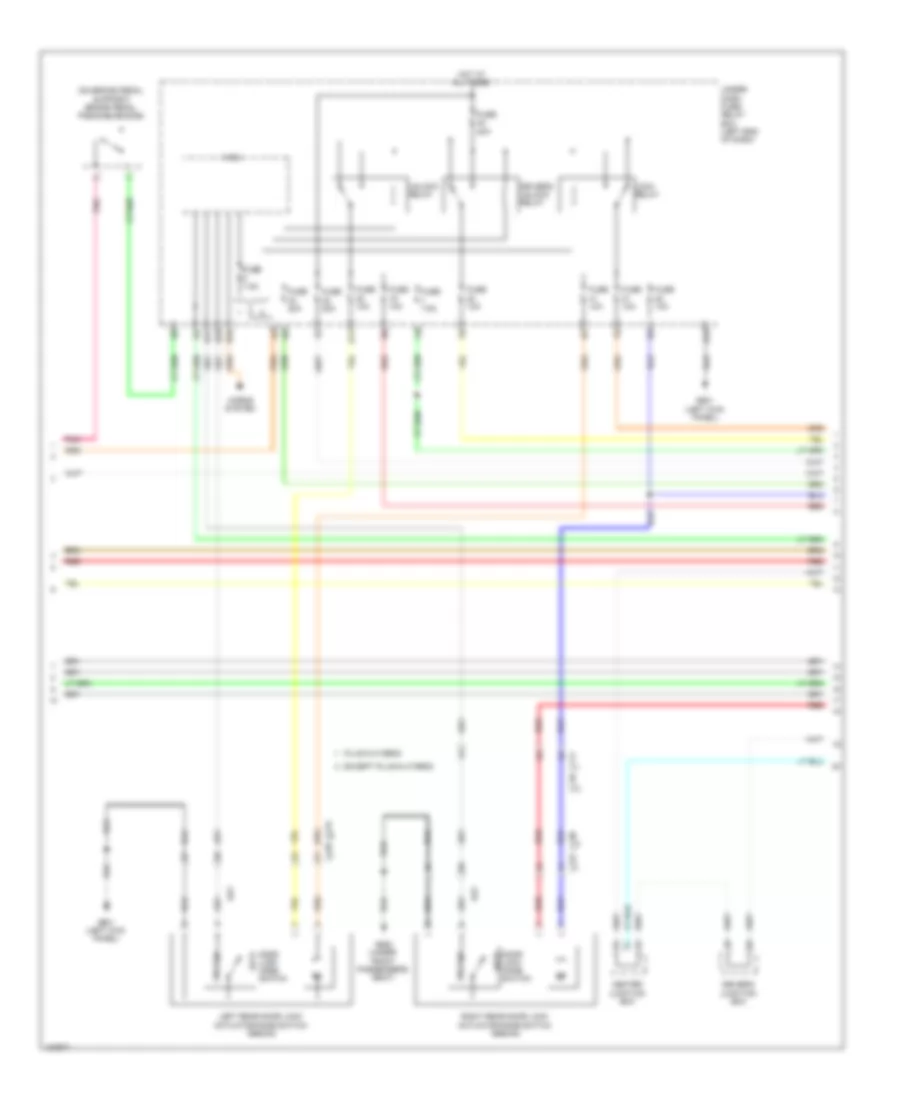
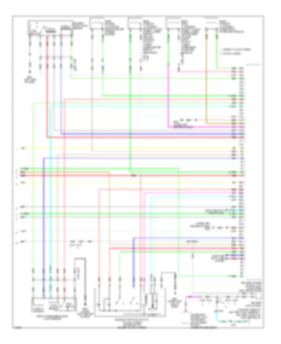
Forced Entry Wiring Diagram, Except Hybrid (3 of 6) for Honda Accord Plug-In 2014
List of elements for Forced Entry Wiring Diagram, Except Hybrid (3 of 6) for Honda Accord Plug-In 2014:
- (on brake pedal support) brake pedal position switch
- (sedan)
- C105
- C109
- C120
- C122
- C130
- Center junction box
- D11
- D16
- D29
- Door lock knob switch
- Door unlock relay
- Driver's junction box
- E34
- Fuse 10a
- Fuse 20a
- Fuse 7.5a
- G601 (left kick panel)
- G652 (under front passenger's seat)
- Horns system
- Hot at all times
- Key
- Left rear door lock actuator/knob switch
- Lock
- Lock relay
- Micu
- P11
- Pnk
- Power seat control unit (3.5l coupe) (under driver's seat)
- Red
- Right rear door lock actuator/knob switch (sedan)
- S17
- Under- dash fuse/ relay box (left end of dash)
- Unlock
- Unlock relay
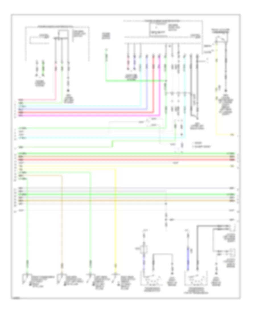
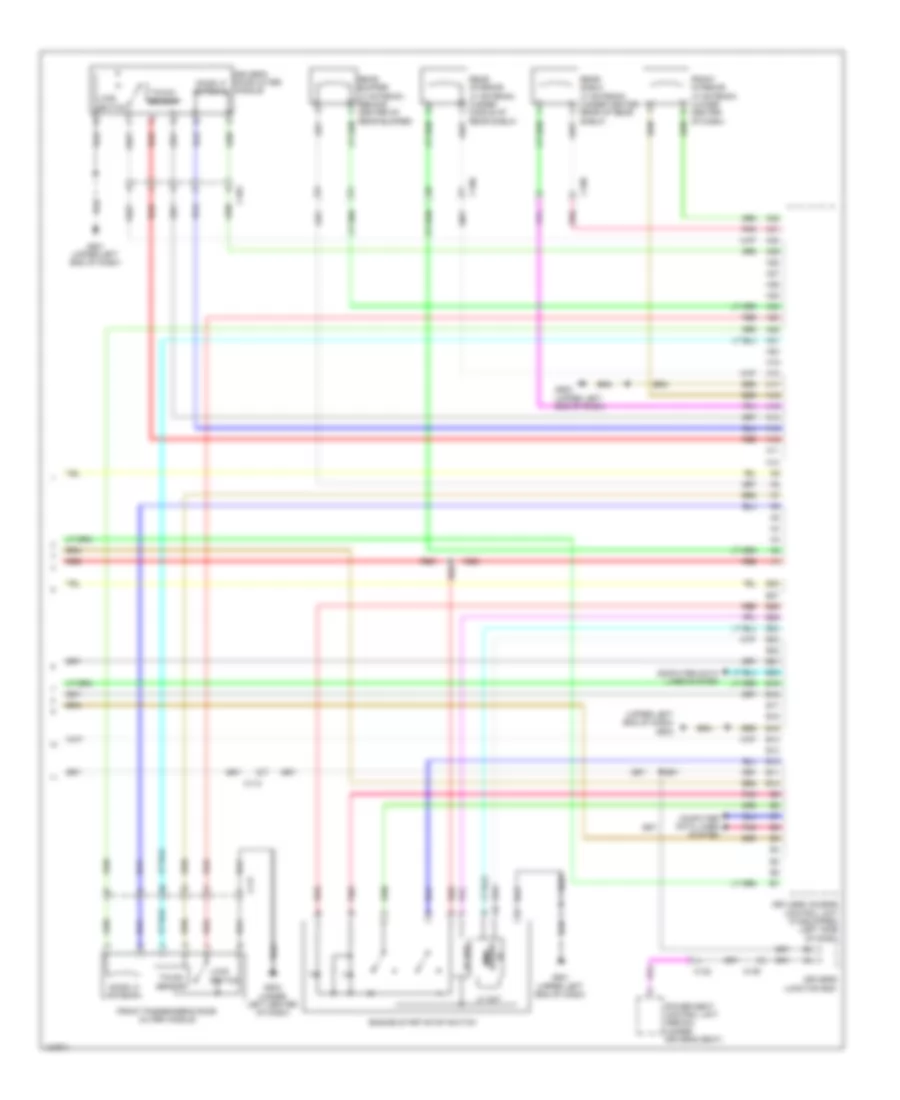
Forced Entry Wiring Diagram, Except Hybrid (4 of 6) for Honda Accord Plug-In 2014
List of elements for Forced Entry Wiring Diagram, Except Hybrid (4 of 6) for Honda Accord Plug-In 2014:
- C104
- C105
- C107
- C110
- C126
- Center junction box
- Control unit
- Coupe
- D22
- D23
- Door lock knob
- Door lock knob switch
- Driver's door key cylinder switch
- Driver's door lock actuator/ knob switch/key cylinder switch
- Driver's door lock knob switch
- Except sport
- Front passenger's door lock actuator/knob switch
- Front passenger's power window switch
- G501 (upper left end of dash)
- G506 (under center of dash)
- Key
- Lock
- Micu
- Moonroof control unit/motor (right front of roof)
- P10
- Pnk
- Red
- S13
- S14
- Sedan
- Sport
- Under- dash fuse/ relay box (left end of dash)
- Unlock
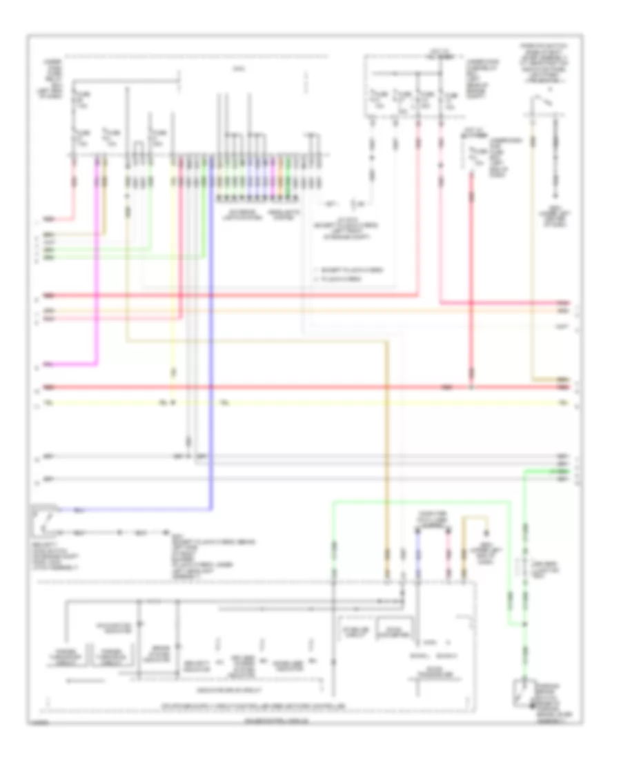
Forced Entry Wiring Diagram, Except Hybrid (5 of 6) for Honda Accord Plug-In 2014
List of elements for Forced Entry Wiring Diagram, Except Hybrid (5 of 6) for Honda Accord Plug-In 2014:
- A/t
- C106
- C110
- C204
- C207
- Computer data lines system
- Control unit
- Coupe
- Cvt
- Driver's door lock switch
- Driver's door switch (at left front "b" pillar)
- Except sport
- Front passenger's door switch (at right front "b" pillar)
- G101 (right front of engine)
- G501 (upper left end of dash)
- G603 (coupe: center rear of luggage compt) (sedan: left rear of luggage compt)
- J/c c012 (left rear of engine compt)
- J/c c013 (top right side of engine)
- Left rear door switch (sedan) (at left rear "c" pillar)
- Lock
- Pnk
- Power mirror switch
- Power window master switch
- Power windows system
- Red
- Right rear door switch (sedan) (at right rear "c" pillar)
- Sedan
- Sport
- Transmission range switch
- Transmission range switch (top of transmission)
- Trunk lid outer handle switch
- Unlock
Forced Entry Wiring Diagram, Except Hybrid (6 of 6) for Honda Accord Plug-In 2014
List of elements for Forced Entry Wiring Diagram, Except Hybrid (6 of 6) for Honda Accord Plug-In 2014:
- (upper left end of dash) g502
- 5v reg
- A10
- A11
- A12
- A13
- A14
- A15
- A16
- A17
- A18
- A19
- A20
- A21
- A22
- A23
- A24
- A25
- A26
- A27
- A28
- A29
- A30
- A31
- A32
- B10
- B11
- B12
- B13
- B14
- B15
- B16
- B17
- B18
- B19
- B20
- B21
- B22
- B23
- B24
- B25
- B26
- B27
- B28
- C103
- C106
- C108
- C109
- C112
- C117
- C122
- Computer data lines system
- Door lf antenna
- Driver's door outer handle
- Driver's junction box
- Engine start/stop switch
- Front interior lf antenna (lower center of dash)
- Front passenger's door outer handle
- G501 (upper left end of dash)
- G502 (upper left end of dash)
- G503 (under left center of dash)
- I/f bilizer immo-
- Keyless access control unit (if equipped) (left side of dash)
- Lf ant
- Lock switch
- Pnk
- Power seat control unit (sedan) (under driver's seat)
- Rear bumper lf antenna (behind center of rear bumper)
- Rear interior lf antenna (under middle of rear shelf)
- Rear shelf lf antenna (under center rear of rear shelf)
- Red
- Touch sensor
Forced Entry Wiring Diagram, Hybrid (1 of 6) for Honda Accord Plug-In 2014
List of elements for Forced Entry Wiring Diagram, Hybrid (1 of 6) for Honda Accord Plug-In 2014:
- (behind left side of rear bumper) smart buzzer
- A17
- Accessory sub relay
- C10
- C102
- C104
- C105
- C11
- C112
- C113
- C12
- C13
- C14
- C15
- C16
- C17
- C18
- C19
- C20
- C21
- C22
- C23
- C24
- Center junction box
- Computer data lines system
- Electric steering lock (on steering column)
- Except plug-in hybrid
- G501 (upper left end of dash)
- G603 (left rear of luggage compt)
- Ig1a relay
- Ig1b relay
- Ig2 relay
- Keyless access control unit (if equipped) (left side of dash)
- Pcm (left front of engine compt)
- Plug-in hybrid
- Pnk
- Red
- Under-dash sub-relay box
Forced Entry Wiring Diagram, Hybrid (2 of 6) for Honda Accord Plug-In 2014
List of elements for Forced Entry Wiring Diagram, Hybrid (2 of 6) for Honda Accord Plug-In 2014:
- (park-pin switch: base of shift lever assembly) a/t gear position indicator panel light/park- pin switch
- A10
- A17
- A30
- A31
- A32
- B-can h
- B-can l
- B-can transceiver
- Brake system indicator
- Computer data lines system
- D20
- D34
- Dc-dc converter
- Driver's junction box
- E15
- E17
- E23
- E24
- Except plug-in hybrid
- Exterior lights system
- F10
- F12
- Forced turning-off circuit
- Forced turning-on circuit
- Fuse 10a
- Fuse 2-7 30a
- Fuse 20a
- Fuse 3-3 30a
- Fuse 7.5a
- G301 (except plug-in hybrid: behind left side of front bumper) (plug-in hybrid: under left headlight assembly)
- G502 (upper left end of dash)
- G503 (under left center of dash)
- Gauge control module
- Headlights system
- Hot at all times
- Immobilizer indicator
- Indicator drive circuit
- J/c c012 (except plug-in hybrid) (left front of engine compt)
- Keyless access system indicator
- M10
- M11
- M12
- Malfunction indicator
- Micu
- P12
- P22
- P24
- Parking brake switch (base of parking brake lever assembly)
- Plug-in hybrid
- Pnk
- Red
- Security hood switch (on engine compt hood lock/ latch assembly)
- Security indicator
- Stabilize circuit
- T10
- Under- dash fuse/ relay box (left end of dash)
- Under-dash sub fuse box (left end of dash)
- Under-hood fuse/relay box (left rear of engine compt)
Forced Entry Wiring Diagram, Hybrid (3 of 6) for Honda Accord Plug-In 2014
List of elements for Forced Entry Wiring Diagram, Hybrid (3 of 6) for Honda Accord Plug-In 2014:
- (on brake pedal support) brake pedal position switch
- C110
- C111
- C122
- C124
- C128
- C130
- Center junction box
- D11
- D16
- D29
- Door lock knob switch
- Driver's junction box
- Driver's unlock relay
- E34
- Except plug-in hybrid
- Fuse 10a
- Fuse 20a
- Fuse 7.5a
- G601 (left kick panel)
- G652 (under front passenger's seat)
- Horns system
- Hot at all times
- Key
- Left rear door lock actuator/knob switch (sedan)
- Lock
- Lock relay
- Micu
- Plug-in hybrid
- Pnk
- Red
- Right rear door lock actuator/knob switch (sedan)
- S17
- Under- dash fuse/ relay box (left end of dash)
- Unlock
- Unlock relay
Forced Entry Wiring Diagram, Hybrid (4 of 6) for Honda Accord Plug-In 2014
List of elements for Forced Entry Wiring Diagram, Hybrid (4 of 6) for Honda Accord Plug-In 2014:
- C105
- C106
- C109
- C110
- C111
- C128
- C132
- Control unit
- D22
- D23
- Door lock knob
- Door lock knob switch
- Driver's door key cylinder switch
- Driver's door lock actuator/ knob switch/key cylinder switch
- Driver's door lock knob switch
- Electro servo brake control unit (right end of dash)
- Except plug-in hybrid
- Front passenger's door lock actuator/knob switch
- Front passenger's power window switch
- G501 (upper left end of dash)
- G503 (under left center of dash)
- Key
- Lock
- Micu
- Plug-in hybrid
- Red
- S13
- S14
- Under- dash fuse/ relay box (left end of dash)
- Unlock
Forced Entry Wiring Diagram, Hybrid (5 of 6) for Honda Accord Plug-In 2014
List of elements for Forced Entry Wiring Diagram, Hybrid (5 of 6) for Honda Accord Plug-In 2014:
- C104
- C105
- C109
- C110
- C203
- Computer data lines system
- Control unit
- Driver's door lock switch
- Driver's door switch (at left front "b" pillar)
- Except plug-in hybrid
- Front passenger's door switch (at right front "b" pillar)
- G101 (left rear of engine)
- G501 (upper left end of dash)
- G603 (left rear of luggage compt)
- Left rear door switch (at left rear "c" pillar)
- Lock
- Plug-in hybrid
- Pnk
- Power mirror switch
- Power window master switch
- Red
- Right rear door switch (at right rear "c" pillar)
- Transmission range switch (top of transmission)
- Trunk lid outer handle switch
- Unlock
Forced Entry Wiring Diagram, Hybrid (6 of 6) for Honda Accord Plug-In 2014
List of elements for Forced Entry Wiring Diagram, Hybrid (6 of 6) for Honda Accord Plug-In 2014:
- (top right rear of battery pack assembly) battery condition monitor module
- (under left center of dash) g503
- 5v reg
- A10
- A11
- A12
- A13
- A14
- A15
- A16
- A17
- A18
- A19
- A20
- A21
- A22
- A23
- A24
- A25
- A26
- A27
- A28
- A29
- A30
- A31
- A32
- B10
- B11
- B12
- B13
- B14
- B15
- B16
- B17
- B18
- B19
- B20
- B21
- B22
- B23
- B24
- B25
- B26
- B27
- B28
- C104
- C105
- C106
- C107
- C108
- C109
- C112
- C113
- C116
- C117
- C125
- C126
- C132
- C401
- Computer data lines system
- Door lf antenna
- Driver's door touch sensor
- Driver's junction box
- Engine start/stop switch (plug-in hybrid) power switch (except plug-in hybrid)
- Except plug-in hybrid
- Front interior lf antenna (under front of center console)
- Front passenger's door touch sensor
- G501 (left side of dash)
- G501 (upper left end of dash)
- G503 (under left center of dash)
- I/f
- Immobilizer
- Keyless access control unit (if equipped) (left side of dash)
- Lf ant
- Lock switch
- Plug-in hybrid
- Pnk
- Power seat control unit/ power seat adjustement switch (under driver's seat)
- Rear bumper lf antenna (behind center of rear bumper)
- Rear interior lf antenna (except plug-in hybrid: under rear of center console) (plug-in hybrid: under center rear of rear shelf)
- Rear shelf lf antenna (except plug-in hybrid: under center rear of rear shelf) (plug-in hybrid: under rear of center console)
- Red
- Touch sensor
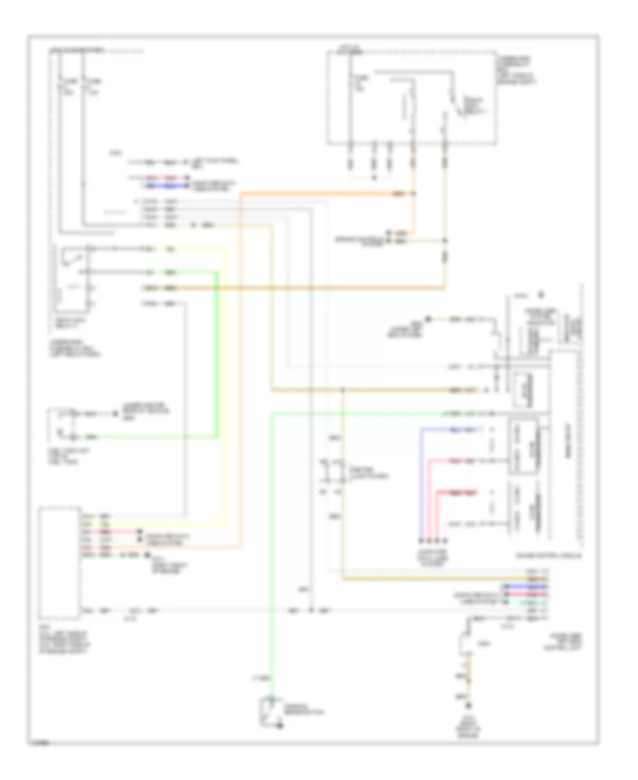
Immobilizer Wiring Diagram, Except Hybrid for Honda Accord Plug-In 2014
List of elements for Immobilizer Wiring Diagram, Except Hybrid for Honda Accord Plug-In 2014:
- (left kick panel) g601
- (under center rear of vehicle)
- A10
- A14
- A17
- A19
- A20
- A21
- A30
- A31
- A32
- B-can h
- B-can l
- B12
- C112
- C204
- Center junction box
- Circuit
- Circuit stabilize
- Computer data lines system
- Converter dc-dc
- E11
- E13
- Engine controls system
- F-can h
- F-can l
- F18
- Fuel tank unit (top of fuel tank)
- Fuse 15a
- Fuse 20a
- Fuse 7.5a
- G101 (right front of engine)
- G502 (upper left end of dash)
- G602
- Gauge control module
- Hot at all times
- Hot in on or start
- Immobilizer keyless control unit
- Immobilizer system indicator
- Indicator drive
- M10
- M11
- M12
- Main circuit
- Micu
- Parking brake switch
- Pcm (2.4l: left side of of engine compt) (3.5l: right side of of engine compt)
- Pgm-fi main relay 1
- Pgm-fi main relay 2
- Pnk
- R10
- Red
- T10
- Transceiver b-can
- Transceiver f-can
- Under-dash fuse/relay box (left end of dash)
- Under-hood fuse/relay box (left side of engine compt)