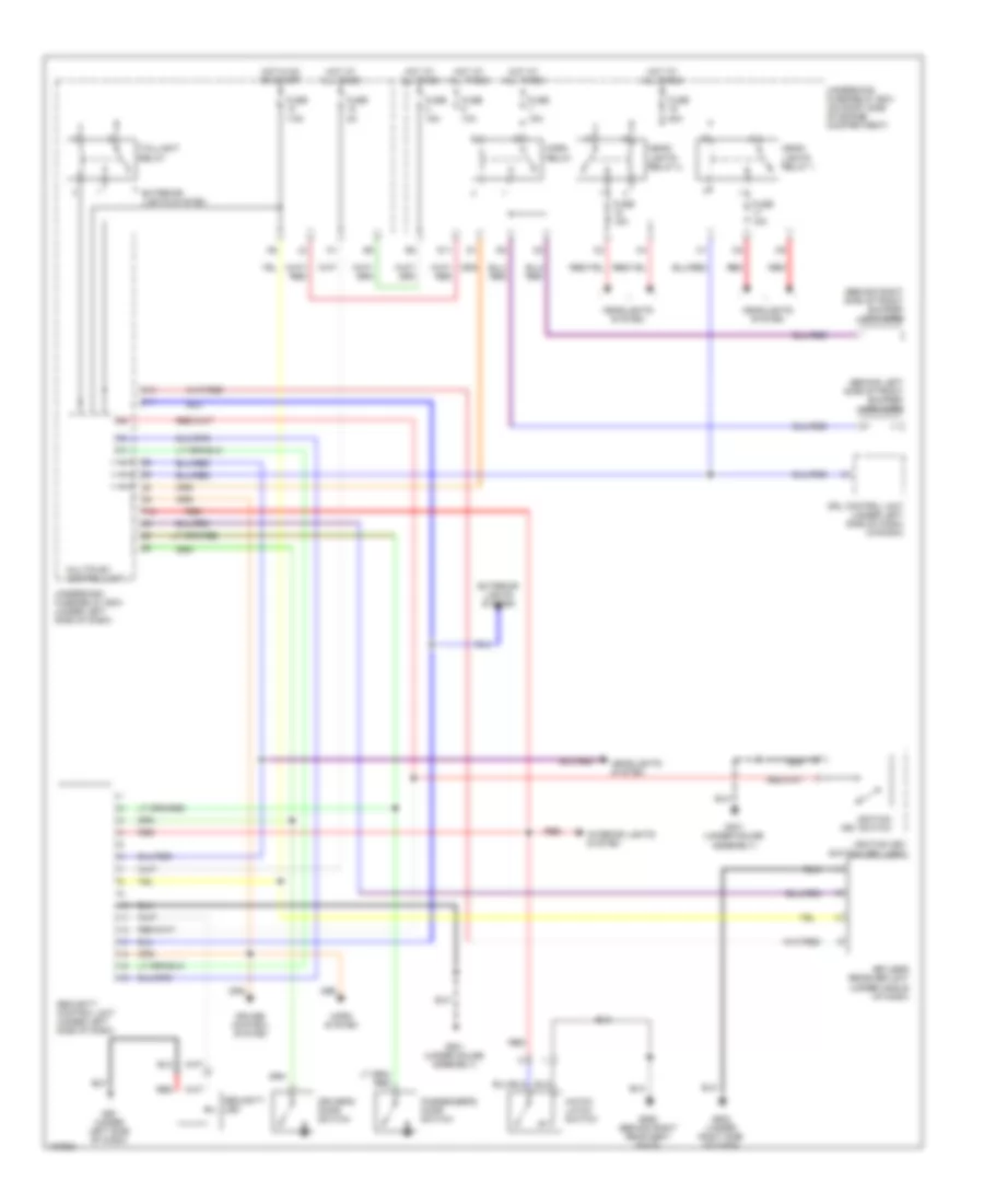
ANTI-THEFT
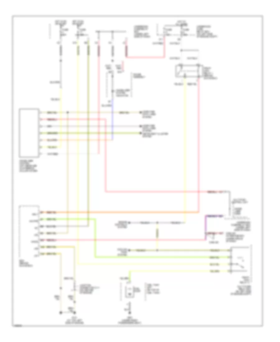
Forced Entry Wiring Diagram, Except Hatchback & Hybrid for Honda Civic GX 2005

List of elements for Forced Entry Wiring Diagram, Except Hatchback & Hybrid for Honda Civic GX 2005:
- (sedan)
- Combination light switch
- Cruise control system
- Driver's door switch
- Front passenger's or passenger's door switch
- Fuse 10 7.5a
- Fuse 15 2a
- Fuse 2 15a
- Fuse 20 20a
- G12 (under left side of dash)
- G401 (under gauge assembly)
- G502 (under center of dash)
- G601 (at center of trunk)
- Headlight switch
- Headlights system
- Horns system
- Hot at all times
- Hot in on or start
- Ignition key switch
- Ignition key switch/ key light
- Interior lights system
- Keyless receiver fuse 1 (under left side of dash)
- Keyless receiver fuse 2 (under left side of dash)
- Keyless receiver unit (under center of dash)
- Left rear door switch (sedan)
- Multiplex control unit
- P18
- Red
- Right rear door switch (sedan)
- Security control unit (under left side of dash)
- Security led
- Taillight relay
- Trunk latch switch (middle of trunk lid)
- Under-dash fuse/relay box (under left side of dash)
- Under-hood fuse/relay box (right side of engine compt)
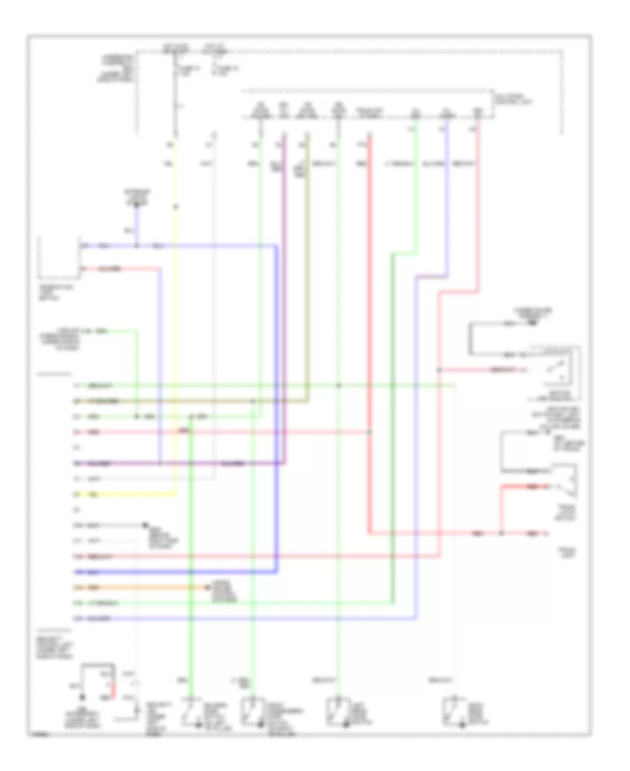
Forced Entry Wiring Diagram, Hatchback for Honda Civic GX 2005
List of elements for Forced Entry Wiring Diagram, Hatchback for Honda Civic GX 2005:
- (behind left side of front bumper) high horn
- (behind right side of front bumper) low horn
- C11
- Cruise control system
- D11
- Driver's door switch
- Drl control unit (under left side of dash) (canada)
- Exterior lights system
- Fuse 10a
- Fuse 15a
- Fuse 2a
- Fuse 7.5a
- Fuse 80a
- G401 (under gauge assembly)
- G50 (under left side of dash)
- G501 (under gauge assembly)
- G502 (under right side of dash)
- G552 (behind right rear seat back)
- Hatch latch switch
- Head- lights relay 1
- Head- lights relay 2
- Headlights system
- Horn relay
- Horn system
- Hot at all times
- Hot in on or start
- Ignition key switch
- Ignition key switch/ key light
- Interior lights system
- K13
- Keyless receiver unit (under middle of dash)
- Multiplex control unit
- P18
- Passenger's door switch
- Red
- Security control unit (under left side of dash)
- Security led
- Taillight relay
- Underdash fuse/relay box (under left side of dash)
- Underhood fuse/relay box (on right side of engine compartment)
Forced Entry Wiring Diagram, Hybrid for Honda Civic GX 2005
List of elements for Forced Entry Wiring Diagram, Hybrid for Honda Civic GX 2005:
- (under gauge assembly) g401
- Carlink a9
- Combination light switch
- Driver's door switch (on left ``b" pillar)
- Drl h/l sw
- Exterior lights system
- Fr door sw (as)
- Fr door sw (dr)
- Front passenger's door switch (on right ``b" pillar)
- Fuse 10 7.5a
- Fuse 15 10a
- G50 (accessory) (under left side of dash)
- G502 (behind right side of dash)
- G601 (at center of trunk)
- Horns, cruise control systems
- Hot at all times
- Hot in on or start
- Ignition key switch
- Ignition key switch/key light (in steering column cover)
- Interface box (under middle of dash)
- K/l set
- K/l unset
- Key sw
- Left rear door switch
- Multiplex control unit
- P18
- Red
- Right rear door switch
- Rr door sw
- Security control unit (under left side of dash)
- Security led (under left side of dash)
- Trunk latch switch
- Trunk light
- Trunk sw (t/g sw)
- Underdash fuse/relay box (under left side of dash)
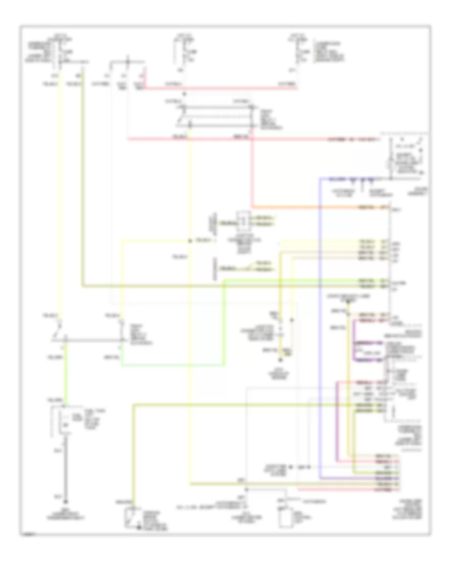
Immobilizer Wiring Diagram, Except GX & Hybrid for Honda Civic GX 2005
List of elements for Immobilizer Wiring Diagram, Except GX & Hybrid for Honda Civic GX 2005:
- (hatchback) (except hatchback)
- (hx, lx, ex)
- (not used)
- A16
- A23
- A24
- A8 carlink interface box (under middle of dash)
- B10
- B19
- B22
- C20
- Car link
- Computer data lines system
- D11
- D12
- Dlc (under center of dash)
- E27
- Ecm/pcm (behind glove box)
- Eps control unit
- Except hatchback
- Except hx, lx, ex
- Fuel pump
- Fuel tank unit (on top of fuel tank)
- Fuse 10a
- Fuse 15a
- G101 (middle of engine)
- G551 (under front passenger's seat)
- Gauge assembly
- Hatchback
- Hatchback except
- Hot at all times
- Hot in on or start
- Hx, lx, ex
- Hx,lx,ex
- Ig1
- Igp1
- Igp2
- Immobi- lizer code
- Immobilizer control unit receiver (in steering column cover)
- Immobilizer system indicator
- Imo fpr
- Imocd
- Junction connector c102 (behind glove compt)
- Junction connector c104 (on cylinder head cover)
- Lg1
- Lg2
- Lg3
- Mrly
- Multiplex control unit
- P14
- Parking brake switch (at base of park lever)
- Pgm-fi main relay 1 (behind glove box)
- Pgm-fi main relay 2 (behind glove box)
- Under-dash fuse/relay box (under left side of dash)
- Under-hood fuse/ relay box (right side of engine compt)
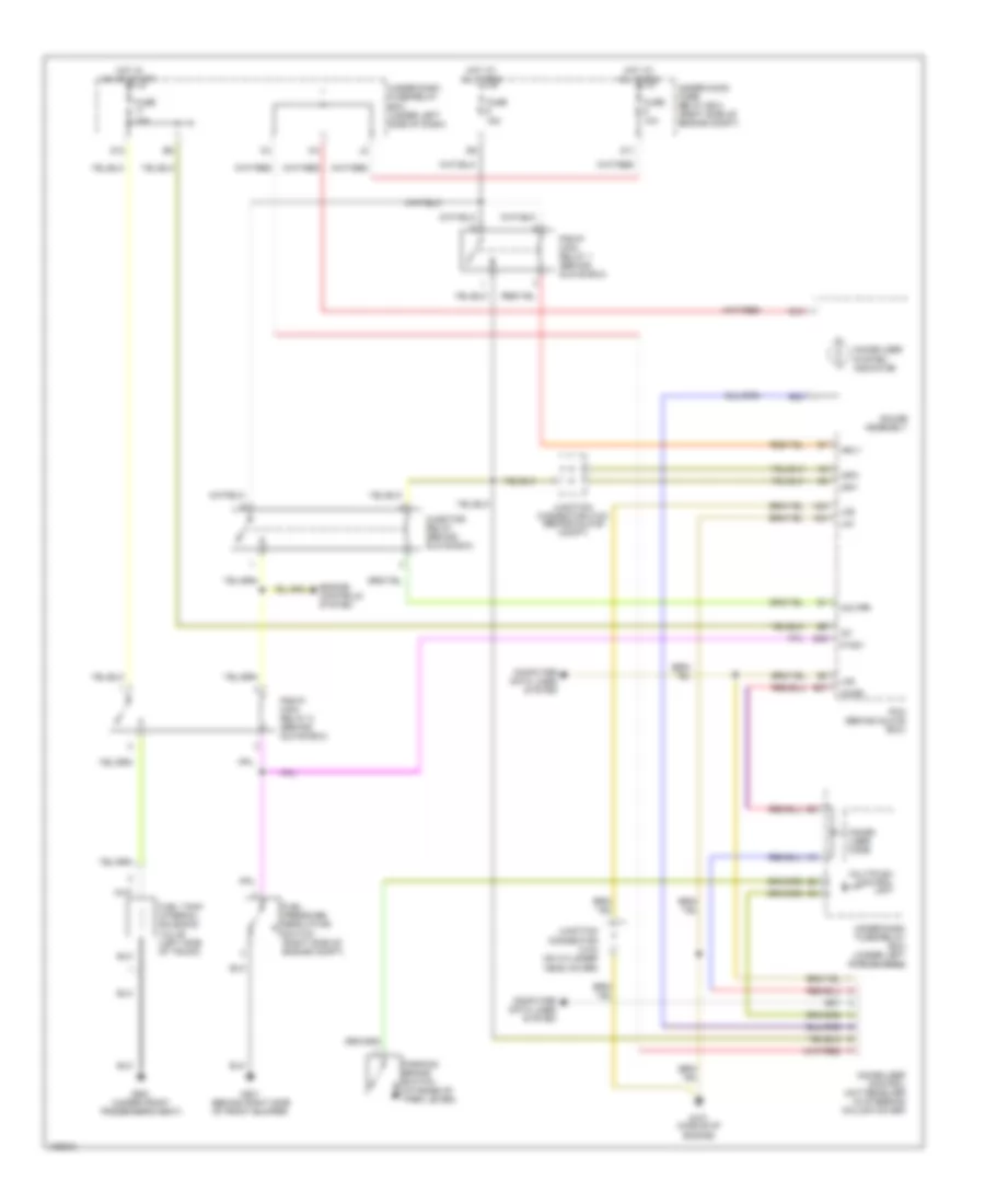
Immobilizer Wiring Diagram, GX for Honda Civic GX 2005
List of elements for Immobilizer Wiring Diagram, GX for Honda Civic GX 2005:
- A23
- A24
- A3 a3
- B10
- B22
- Computer data lines system
- D11
- D12
- E27
- E28
- Engine controls system
- Fuel pressure regulator switch (right side of engine compt)
- Fuel tank internal solenoid valve (left side of trunk)
- Fuse 10a
- Fuse 15a
- G101 (middle of engine)
- G201 (behind right side of front bumper)
- G551 (under front passenger's seat)
- Gauge assembly
- Hot at all times
- Hot in on or start
- Ig1
- Igp1
- Igp2
- Immobi- lizer code
- Immobilizer control unit receiver (in steering column cover)
- Immobilizer system indicator
- Imo fpr
- Imocd
- Injector relay (behind glove box)
- Junction connector c102 (behind glove compt)
- Junction connector c104 (on cylinder head cover)
- Lg1
- Lg2
- Lg3
- Mrly
- Multiplex control unit
- P1sw
- Parking brake switch (at base of park lever)
- Pcm (behind glove box)
- Pgm-fi main relay 1 (behind glove box)
- Pgm-fi main relay 2 (behind glove box)
- Under-dash fuse/relay box (under left side of dash)
- Under-hood fuse/ relay box (right side of engine compt)
Immobilizer Wiring Diagram, Hybrid for Honda Civic GX 2005
List of elements for Immobilizer Wiring Diagram, Hybrid for Honda Civic GX 2005:
- A23
- A24
- B18
- Carlink
- Carlink iinterface box (under middle of dash)
- Computer data lines system
- Cooling fans system
- D11
- D12
- E27
- Ecm (behind glove box)
- Engine controls system
- Fuel pump
- Fuel tank unit (on top of fuel tank)
- Fuse 10a
- Fuse 15a
- G101 (at top left side of engine)
- G551 (under front passenger's seat)
- Gauge assembly
- Hot at all times
- Hot in on or start
- Ig1
- Immobi- lizer cord
- Immobilizer control unit receiver (in steering column cover)
- Immobilizer system indicator
- Imo fpr
- Imocd
- Instrument cluster system
- Junction connector c111 (on center of engine)
- Lg1
- Lg2
- Lg3
- Mrly
- Multi-fuse/ relay box (on left side of engine compt)
- Multiplex control unit
- Pgm-fi main relay 1 (behind glove box)
- Pgm-fi main relay 2
- Underdash fuse/relay box (under left side of dash)
- Underhood fuse/ relay box (on left side of engine compt)