ANTI-THEFT
Anti-theft Wiring Diagram for Honda CR-V LX 2003

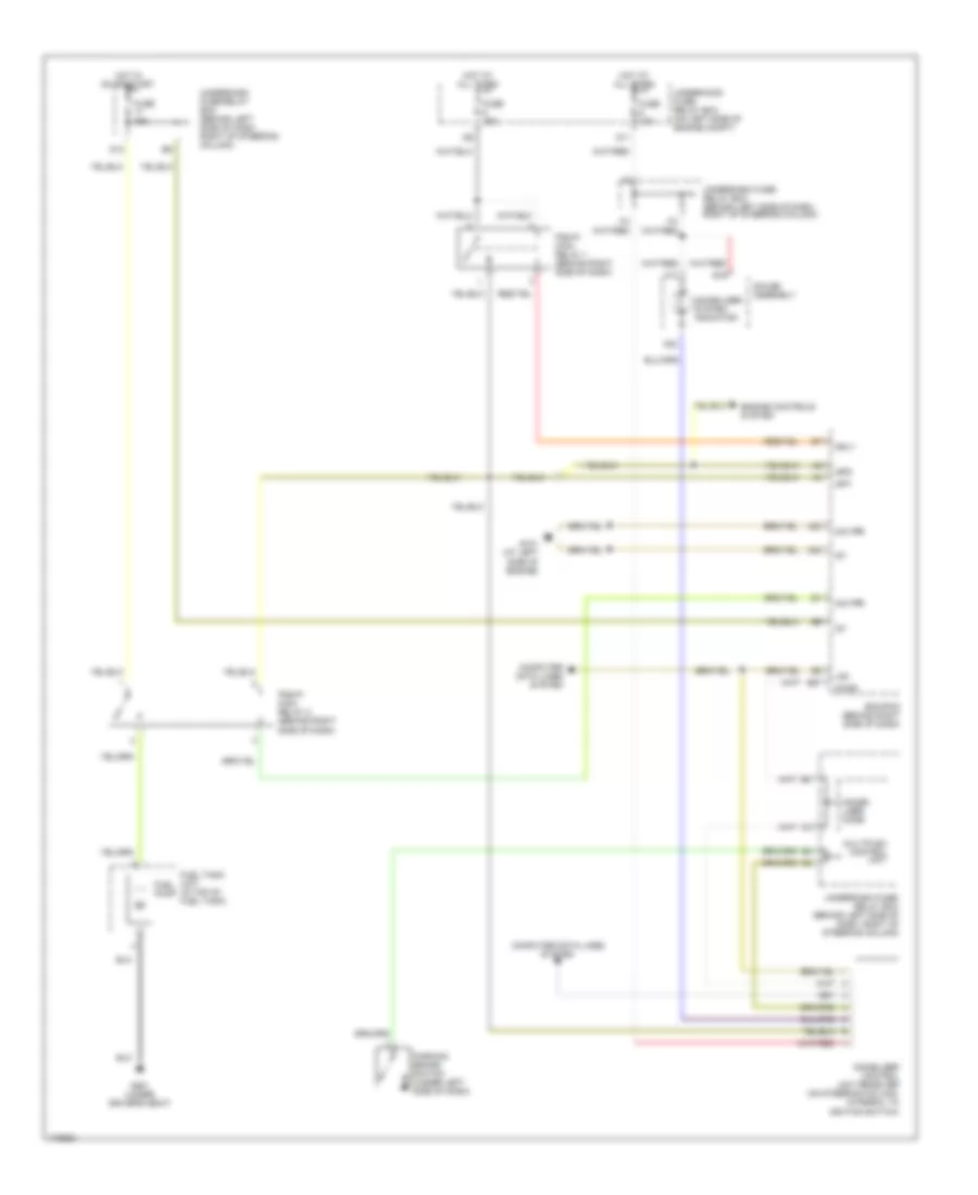
List of elements for Anti-theft Wiring Diagram for Honda CR-V LX 2003:
- (behind glove box) g401
- Combination light switch
- Driver's door switch
- Drl h/l sw
- Fr door sw (dr)
- Front passenger's door switch
- Fuse 40a
- Fuse 7.5a
- G/h act
- G/h sw
- G50 (under left side of dash)
- G501 (under left side of dash)
- G601 (behind right quarterpanel)
- G701 (at middle of tailgate)
- Hatch glass actuator (on middle of tailgate)
- Hatch glass latch switch 1 (on middle of tailgate)
- Hood switch (at center front of engine compt)
- Horn sw
- Horns system
- Hot at all times
- Hot in on or start
- Ignition key switch
- Ignition key switch/key switch
- Interior lights system
- K/l set
- K/l unset
- Key sw
- Left rear door switch
- Microphone
- Multiplex control unit
- Other door sw
- P18
- Rear ceiling light diode (under right side of dash)
- Rear wiper control unit (behind right rear quarterpanel)
- Red
- Right rear door switch
- Security control unit (under left side of dash)
- Security in-line fuse (in underdash fuse/relay box)
- Security led
- Tailgate switch
- Trunk sw (t/g sw)
- Underdash fuse/relay box (behind left side of dash, right of steering column)
- Underdash fuse/relay box connector (not used)
- Underhood fuse/relay box (on left side of engine compartment)
Immobilizer Wiring Diagram for Honda CR-V LX 2003
List of elements for Immobilizer Wiring Diagram for Honda CR-V LX 2003:
- A10
- A22
- A23
- A24
- B19
- Computer data lines system
- D11
- D12
- E27
- Ecm/pcm (behind right side of dash)
- Engine controls system
- Fuel pump
- Fuel tank unit (in top of fuel tank)
- Fuse 10a
- Fuse 15a
- G101 (at left side of engine)
- G551 (under driver's seat)
- Gauge assembly
- Hot at all times
- Hot in on or start
- Ig1
- Igp1
- Igp2
- Immobi- lizer code
- Immobilizer system indicator
- Immoblizer control unit receiver (on steering column, integral to ignition switch)
- Imo fpr
- Imocd
- Lg3
- Mrly
- Multiplex control unit
- Parking brake switch (under left side of dash)
- Pgm-fi main relay 1 (behind right side of dash)
- Pgm-fi main relay 2 (behind right side of dash)
- Underdash fuse/ relay box (behind left side of dash, right of steering column)
- Underdash fuse/relay box (behind left side of dash, right of steering column)
- Underhood fuse/ relay box (on left side of engine compt)