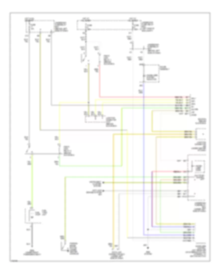
ANTI-THEFT
Forced Entry Wiring Diagram for Honda Element EX 2005

List of elements for Forced Entry Wiring Diagram for Honda Element EX 2005:
- (not used)
- Back up (b+)
- C11
- Combination switch
- D11
- Driver's door switch
- Drl h/l sw
- Fr door sw
- Front passenger's door switch
- Fuse 10a
- Fuse 15a
- Fuse 7.5a
- G401 (under center of dash)
- G501 (under left side of dash)
- G553 (left "d" pillar)
- Hatch latch switch
- Headlight switch
- Horn
- Horn relay
- Horn sw
- Horns system
- Hot at all times
- Hot in on or start
- Ig1 meter
- Ignition key switch
- Ignition key switch/key light
- Interior lights system
- Junction connector 456 (under center of dash)
- K/l set
- K/l unset
- K13
- Key sw
- Keyless receiver unit (optional) (under center of dash)
- Left tailgate switch
- Lighting rly
- Microphone
- Multiplex control unit
- Nca
- Other door sw
- P18
- Red
- Right tailgate switch
- Security control unit (under left side of dash)
- Security led
- Small lt rly
- Trunk sw
- Underdash fuse/relay box (under left side of dash)
- Underhood fuse/relay box (on left side of engine compartment)
Immobilizer Wiring Diagram for Honda Element EX 2005
List of elements for Immobilizer Wiring Diagram for Honda Element EX 2005:
- Anti-lock brakes system (ex)
- B15
- B16
- D11
- D12
- Data link connector (dlc) (under left side of dash)
- E17
- E27
- Ecm/pcm (behind glove box)
- Fuel pump
- Fuel tank unit
- Fuse 10a
- Fuse 15a
- G552 (under front pasenger's seat)
- Gauge assembly
- Hot at all times
- Hot in on or start
- Ig1
- Igp1
- Igp2
- Immobi- lizer code
- Immobilizer system indicator
- Immoblizer control unit receiver (on steering column integral to ignition switch)
- Imo fpr
- Imocd
- Instrument cluster system
- Junction conector c107 (behind glove box)
- Junction connector (under center of dash)
- Lg3
- Mrly
- Multiplex control unit
- P14
- Parking brake switch (under center console)
- Pgm-fi main relay 1 (behind glove box)
- Pgm-fi main relay 2 (behind glove box)
- Srs system
- Underdash fuse/relay box (behind left side of dash)
- Underdash fuse/relay box (under left side of dash)
- Underhood fuse/ relay box (left side of eng compt)