ANTI-THEFT
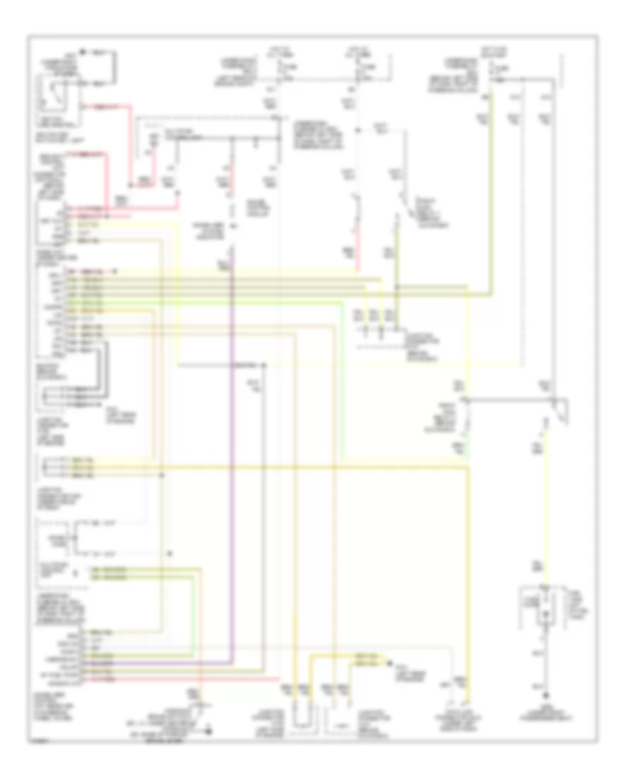
Forced Entry Wiring Diagram, Accessory for Honda Element EX 2009

List of elements for Forced Entry Wiring Diagram, Accessory for Honda Element EX 2009:
Immobilizer Wiring Diagram for Honda Element EX 2009
List of elements for Immobilizer Wiring Diagram for Honda Element EX 2009: