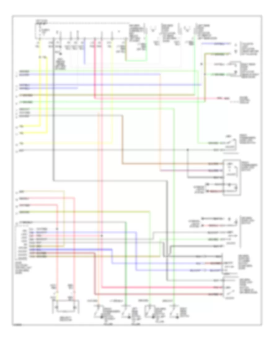
ANTI-THEFT
Forced Entry Wiring Diagram, EX, EX-L (1 of 2) for Honda Pilot LX 2006

List of elements for Forced Entry Wiring Diagram, EX, EX-L (1 of 2) for Honda Pilot LX 2006:
- (below right front seat) g651
- (not used)
- +b clock
- +b d/l
- A10
- A11
- A12
- A13
- A14
- A15
- A16
- A17
- A21
- A22
- A23
- A24
- Antenna
- B11
- B14
- B21
- B22
- Bus (door/dr)
- Bus as
- Bus dr
- C14
- C16
- C20
- D/l lock
- D/l unlck dr
- D/l unlock
- Door lock
- Door unlock
- Dr sw as
- Dr sw dr
- Dr sw ra
- Dr sw rd
- Driver's multiplex control unit
- Driver's under-dash fuse/relay box (below left end of dash)
- E10
- E15
- E17
- Front passenger's door lock actuator (rear of front passenger's door)
- Fuse 12 20a
- Fuse 13 7.5a
- G15
- G201 (behind right headlight)
- G401 (behind upper left end of dash)
- G501
- G503 (behind right end of dash)
- G601 (below left front seat)
- G651 (below right front seat)
- G652 (above right rear fender)
- Gnd
- H/l rly+
- H14
- Headlights system
- Hood sw
- Horn rly
- Horns system
- Hot at all times
- I12
- I14
- Ig key sw
- Ig1
- Ig1 meter
- Ignition key switch
- Ignition key switch/ key light
- Instrument cluster system
- Interior lights system
- Intrlt
- K/c as lock
- K/c as unlock
- K/l lock
- K/l panic
- K/l unlock
- Keyless receiver unit (behind right side of glove box)
- Left rear door lock knob switch (at rear of left rear door)
- M19
- Nca
- Panic
- Passenger's multiplex control unit
- Passenger's under-dash fuse/relay box (behind right kick panel)
- Pnk
- Radio sw
- Rem as lock
- Rem as unlock
- Right rear door lock knob switch
- Scty in
- Security hood switch (at center front of engine compt)
- Sgnd
- Sil as unlock
- Sil ra unlock
- Sil rd unlock
- Sound systems
- T/g sw
- Tailgate latch switch (in tailgate)
- Tailgate lights
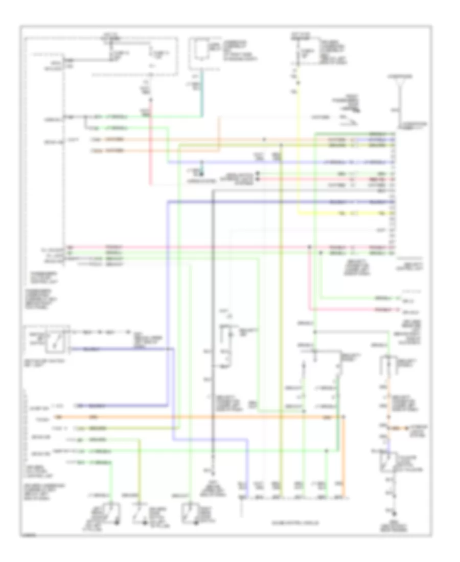
Forced Entry Wiring Diagram, EX, EX-L (2 of 2) for Honda Pilot LX 2006
List of elements for Forced Entry Wiring Diagram, EX, EX-L (2 of 2) for Honda Pilot LX 2006:
- A12
- A15
- A16
- A17
- A18
- B30
- Door multiplex control unit (in driver's door)
- Driver's door key cylinder switch (in driver's door)
- Driver's door lock actuator (at rear of driver's door)
- Driver's door lock knob switch (at rear of driver's door)
- Driver's door lock switch
- Driver's door switch (on left ``b" pillar)
- Driver's underdash fuse/relay box (below left end of dash)
- Front passenger's door lock knob switch
- Front passenger's door lock switch
- Front passenger's door switch (on right ``b" pillar)
- Fuse 9 10a
- G401 (behind upper left end of dash)
- Gauge control module
- H16
- Hot in on or start
- Interior lights system
- K13
- L13
- Left rear door lock actuator (at rear of left rear door)
- Left rear door switch (on left ``c" pillar)
- Lock
- Mpx-dr
- Pnk
- Right rear door lock actuator (rear of right rear door)
- Right rear door switch
- Security indicator
- Tailgate lock actuator (near center of tailgate)
- Unlock
- Vbu
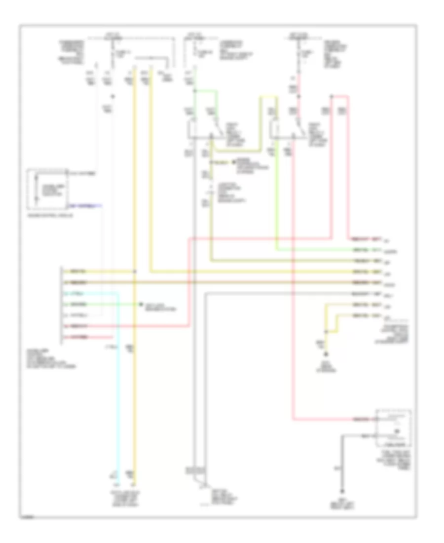
Forced Entry Wiring Diagram, LX for Honda Pilot LX 2006
List of elements for Forced Entry Wiring Diagram, LX for Honda Pilot LX 2006:
- +b clock
- +b d/l
- A11
- A13
- A14
- A15
- A16
- A17
- A23
- A24
- B14
- B16
- B17
- B27
- B28
- B34
- B35
- C14
- C16
- Dr lk
- Dr sw as
- Dr sw dr
- Dr sw ra
- Dr sw rd
- Dr unlk
- Driver's door switch (on left ``b" pillar)
- Driver's multiplex control unit
- Driver's underdash fuse/relay box (below left end of dash)
- E10
- Front passenger's door switch
- Fuse 12 20a
- Fuse 13 7.5a
- Fuse 9 10a
- G401 (behind upper left end of dash)
- G652 (above right rear fender)
- Gauge control module
- H16
- Headlights & exterior lights systems
- Horn relay
- Horn rly
- Horns system
- Hot at all times
- Hot in on or start
- I12
- Ig key sw
- Ignition key switch
- Ignition key switch/ key light
- Interior lights system
- J14
- J15
- K/l lock
- K/l unlock
- Keyless receiver unit (behind right side of glove box)
- Left rear door switch (on left "c" pillar)
- Microphone
- Microphone jack
- Nca
- Passenger's multiplex control unit
- Passenger's under-dash fuse/relay box (behind right kick panel)
- Right rear door switch
- Security connector (under left side of dash)
- Security control unit
- Security diode 1
- Security diode 2
- Security led
- T/g sw
- Tailgate latch switch (in tailgate)
- Underhood fuse/relay box (at right side of engine compt)
Immobilizer Wiring Diagram for Honda Pilot LX 2006
List of elements for Immobilizer Wiring Diagram for Honda Pilot LX 2006:
- (not used)
- A11
- A17
- A1o
- A22
- A44
- Anti-lock brakes system
- B18
- B37
- B43
- C40
- Data link (dlc) connector (lower left side of dash)
- Driver's under-dash fuse/relay box (below left end of dash)
- Engine controls & air conditioning systems
- Fuel pump
- Fuel tank unit (under second row seat, below floor access panel)
- Fuse 1 15a
- Fuse 13 7.5a
- Fuse 46 15a
- G101 (rear of engine)
- G14
- G16
- G601 (below left front seat)
- Gauge control module
- Hot at all times
- Hot in on or start
- I12
- Ig1
- Ignition coil relay (behind right kick panel)
- Igp
- Immobilizer control unit receiver (in steering column, on ignition key cylinder)
- Immobilizer system indicator
- Imocd
- Imofpr
- Junction connector c103 (rear of engine compt)
- Lg1
- Lg2
- Lg3
- Mrly
- Passenger's under-dash fuse/relay box (behind right kick panel)
- Pgm-fi main relay 1 (under left side of dash)
- Pgm-fi main relay 2 (under left side of dash)
- Powertrain control (pcm) module (right side of engine compt)
- Underhood fuse/relay box (at right side of engine compt)