ANTI-THEFT
Anti-theft Wiring Diagram (1 of 2) for Honda Prelude Type SH 1997

List of elements for Anti-theft Wiring Diagram (1 of 2) for Honda Prelude Type SH 1997:
- (left front corner of engine compartment) g100
- (left kick panel) g200
- (right kick panel) g203
- (right rear of trunk) g405
- 15a
- 7.5a
- Antenna
- Antenna input
- Battery
- C251
- C254
- C551
- Clock radio fuse 43 7.5a
- Disarm/ valet switch (on lower left dash panel)
- Disarm/valet sw in
- Door open input
- Dr unlck rly ctrl
- Ecu eat ecu fuse 14 15a
- Exterior & interior light systems
- Glass breakage microphone
- Ground
- Hood sw input
- Hood switch (on front of engine compartment, next to hood latch)
- Horn ctrl
- Horns system
- Hot at all times
- Hot in on or start
- Ign key sw input
- Ignition
- Ignition key switch
- Light flash ctrl
- Light flasher relay (on back of lower left dash panel)
- Lock output
- Nca
- Optional
- Power distribution system
- Red
- Sec ind ctrl
- Security control unit (behind dash, above accelerator pedal)
- Security in-line fuse holder 1 (behind dash, above left kick panel)
- Security in-line fuse holder 2 (behind lower dash panel, left of steering column, taped to harness)
- Security in-line fuse holder 3 (behind lower dash panel, left of steering column, taped to harness)
- Security indicator
- Siren (behind left side of front bumper) (optional)
- Siren ctrl
- Small light fuse 42 20a
- Steering lock
- Trunk latch switch (on center of trunk lid, at latch assembly)
- Trunk open input
- Underdash fuse/relay box (behind left kick panel)
- Underhood fuse/relay box (on right rear corner of engine compartment)
- Unlock output
- Warning systems
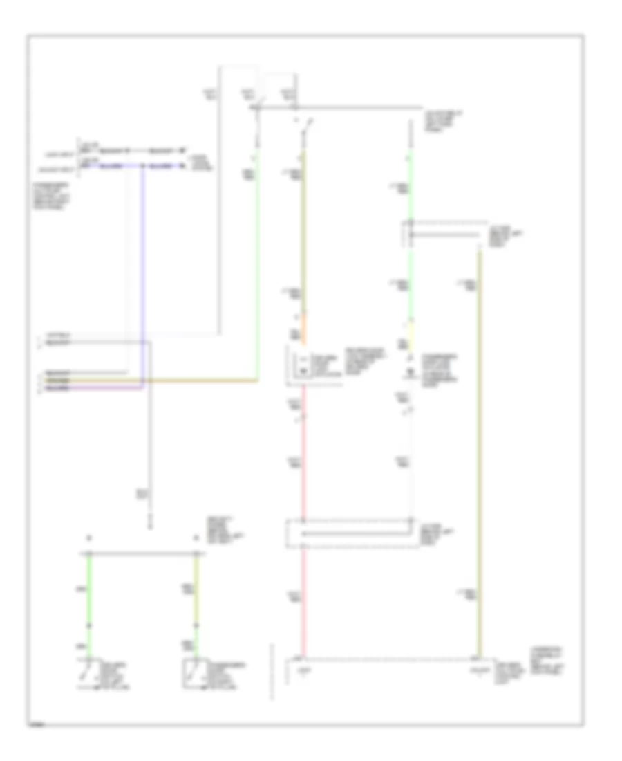
Anti-theft Wiring Diagram (2 of 2) for Honda Prelude Type SH 1997
List of elements for Anti-theft Wiring Diagram (2 of 2) for Honda Prelude Type SH 1997:
- (d4 or b4)
- (d5 or b5)
- Door locks system
- Driver's door lock actuator
- Driver's door lock assembly (in rear of driver's door)
- Driver's door switch (in left "b" pillar)
- Driver's multiplex control unit
- J/c c406 (behind left side of dash)
- Lock +
- Lock input
- Passenger's door lock actuator (in rear of passenger's door)
- Passenger's door switch (in right "b" pillar)
- Passenger's multiplex control unit (behind right kick panel)
- Security diodes (behind driver's left air vent)
- Underdash fuse/relay box (behind left kick panel)
- Unlock +
- Unlock input
- Unlock relay (on lower left dash panel)
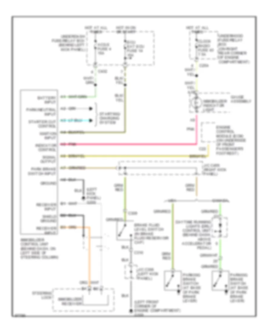
Immobilizer Wiring Diagram for Honda Prelude Type SH 1997
List of elements for Immobilizer Wiring Diagram for Honda Prelude Type SH 1997:
- (left front corner of engine compartment) g100
- (left kick panel) g200
- A1 battery input
- A10
- A2 park/neutral input
- A3 starter cut control
- A4 ignition input
- A5 indicator control
- A6 signal output
- A7 park brake switch input
- Acg-s fuse 4 15a
- B1 receiver input
- B2 shield ground
- B3 receiver input
- Brake fluid level switch (in brake fluid reservoir cap)
- C22
- C254
- C309
- C310
- C432
- Canada
- Clock radio fuse 43 7.5a
- Daytime running lights (drl) control unit (behind dash, above accelerator pedal)
- Ecu eat ecu fuse 14 15a
- Engine control module (ecm) (on underside of front passenger's footrest)
- Gauge assembly
- Ground
- Hot at all times
- Hot in on or start
- Immobilizer control unit (behind dash, on left side of steering column)
- Immobilizer indicator light
- Immobilizer receiver
- J/c c306 (left kick panel)
- J/c c456 (right kick panel)
- Parking brake switch (at base of park brake lever)
- Pnk
- Starting/ charging system
- Steering lock
- Underdash fuse/relay box (behind left kick panel)
- Underhood fuse/relay box (on right rear corner of engine compartment)
- Usa