ANTI-THEFT
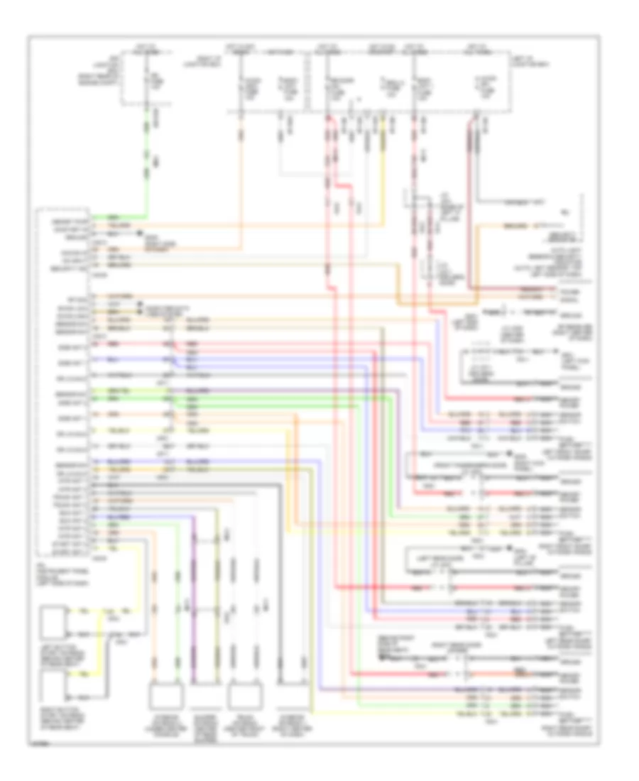
Forced Entry Wiring Diagram (1 of 4) for Hyundai Equus Ultimate 2013

List of elements for Forced Entry Wiring Diagram (1 of 4) for Hyundai Equus Ultimate 2013:
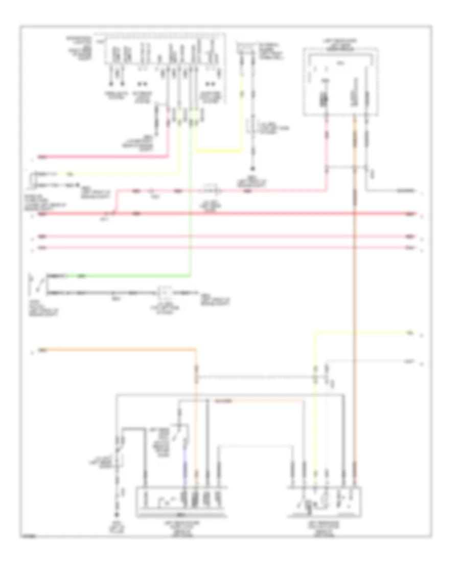
Forced Entry Wiring Diagram (2 of 4) for Hyundai Equus Ultimate 2013
List of elements for Forced Entry Wiring Diagram (2 of 4) for Hyundai Equus Ultimate 2013:
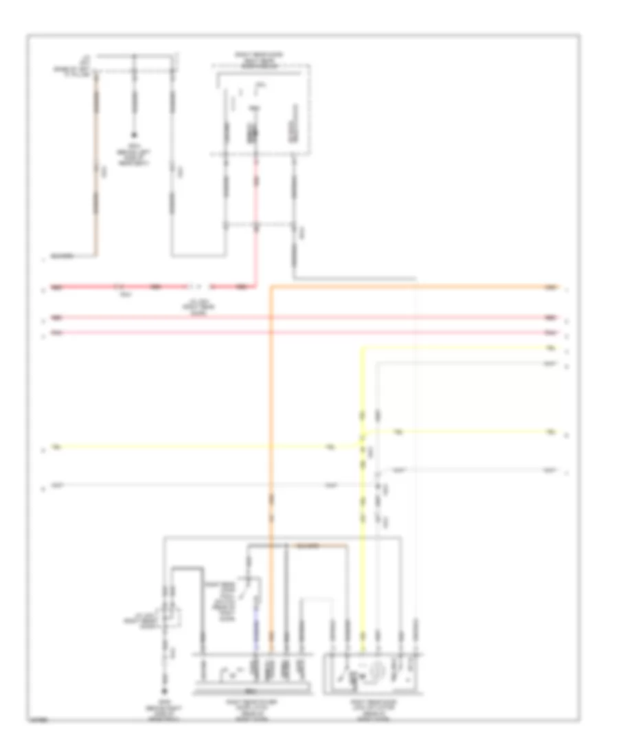
Forced Entry Wiring Diagram (3 of 4) for Hyundai Equus Ultimate 2013
List of elements for Forced Entry Wiring Diagram (3 of 4) for Hyundai Equus Ultimate 2013:
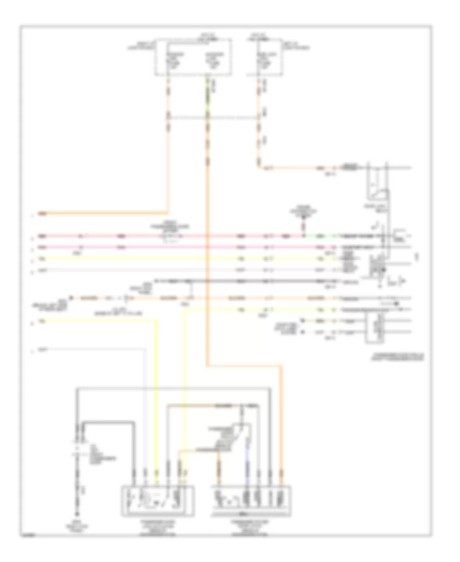
Forced Entry Wiring Diagram (4 of 4) for Hyundai Equus Ultimate 2013
List of elements for Forced Entry Wiring Diagram (4 of 4) for Hyundai Equus Ultimate 2013:
Immobilizer Wiring Diagram for Hyundai Equus Ultimate 2013
List of elements for Immobilizer Wiring Diagram for Hyundai Equus Ultimate 2013: