ANTI-THEFT
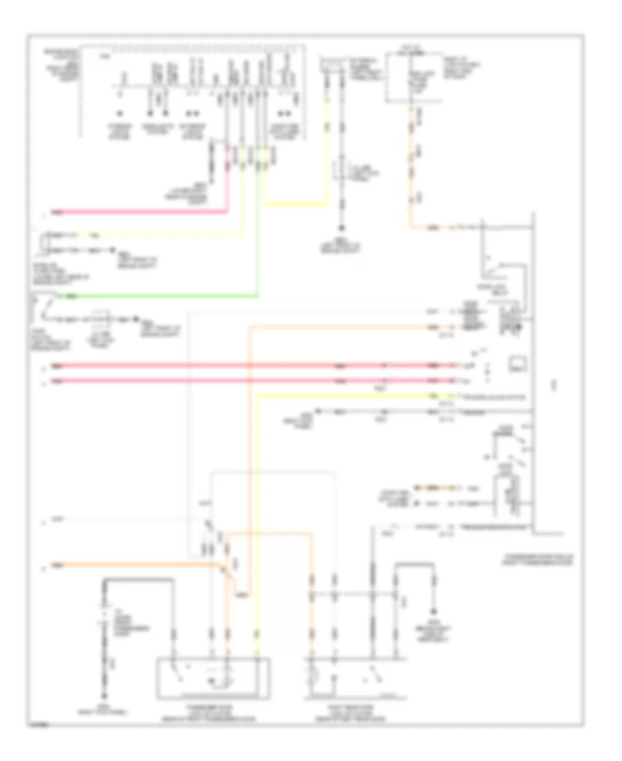
Forced Entry Wiring Diagram (1 of 2) for Hyundai Genesis 5.0 R-Spec 2013

List of elements for Forced Entry Wiring Diagram (1 of 2) for Hyundai Genesis 5.0 R-Spec 2013:
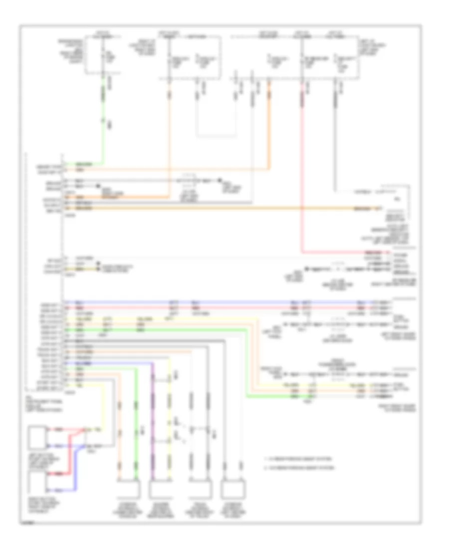
Forced Entry Wiring Diagram (2 of 2) for Hyundai Genesis 5.0 R-Spec 2013
List of elements for Forced Entry Wiring Diagram (2 of 2) for Hyundai Genesis 5.0 R-Spec 2013:
Immobilizer Wiring Diagram, with Button Start for Hyundai Genesis 5.0 R-Spec 2013
List of elements for Immobilizer Wiring Diagram, with Button Start for Hyundai Genesis 5.0 R-Spec 2013:
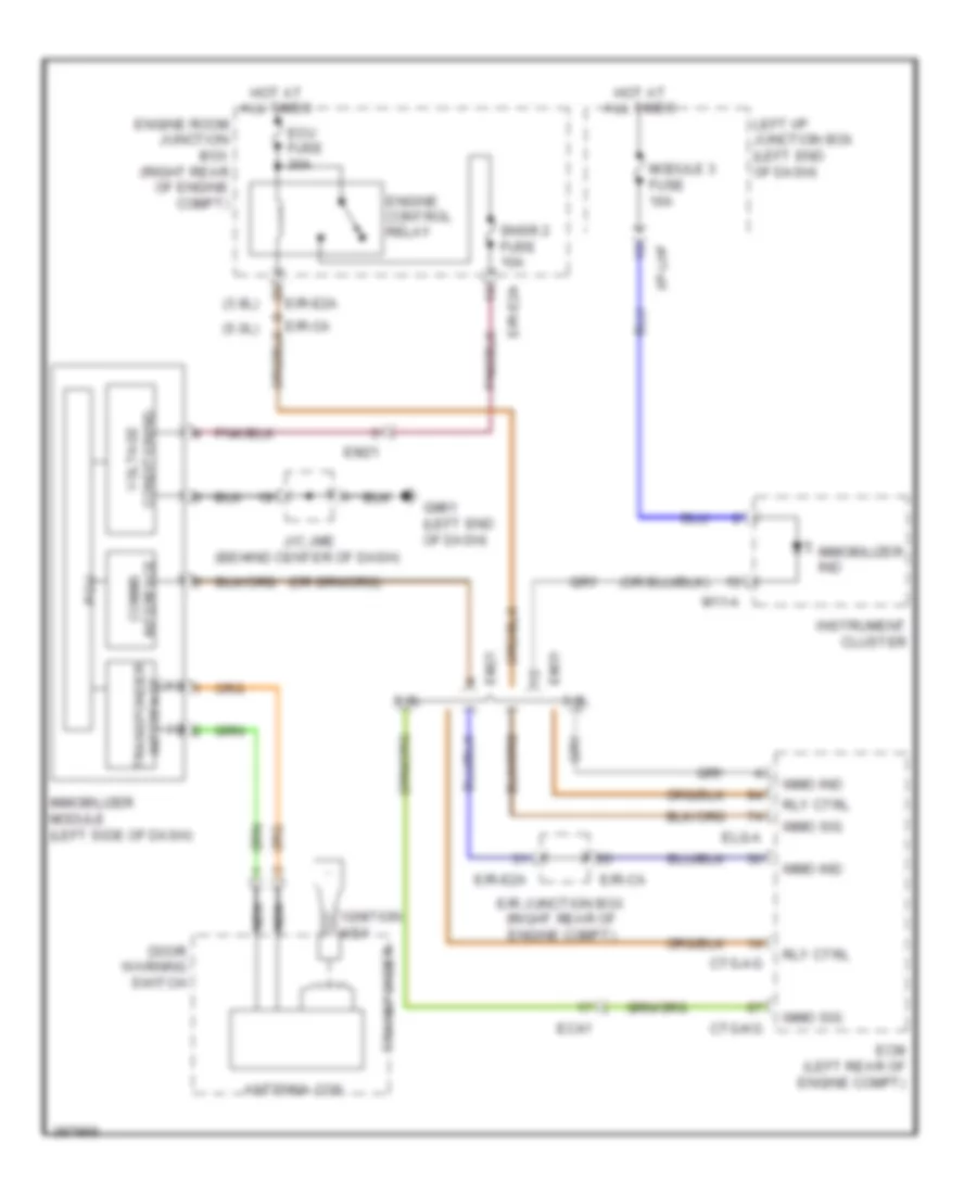
Immobilizer Wiring Diagram, without Button Start for Hyundai Genesis 5.0 R-Spec 2013
List of elements for Immobilizer Wiring Diagram, without Button Start for Hyundai Genesis 5.0 R-Spec 2013: