ANTI-THEFT
Forced Entry Wiring Diagram for Hyundai Veracruz Limited 2012

List of elements for Forced Entry Wiring Diagram for Hyundai Veracruz Limited 2012:
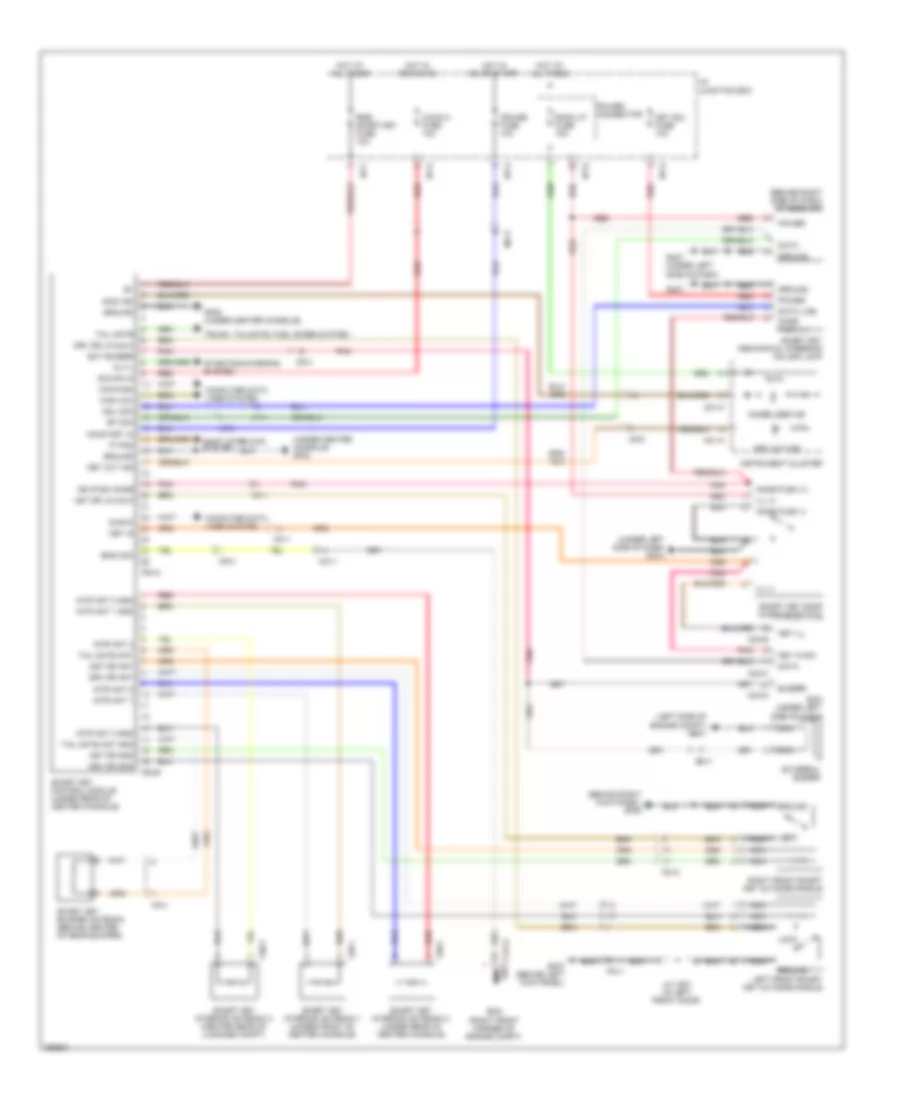
Immobilizer Wiring Diagram, with Smart Key System for Hyundai Veracruz Limited 2012
List of elements for Immobilizer Wiring Diagram, with Smart Key System for Hyundai Veracruz Limited 2012:
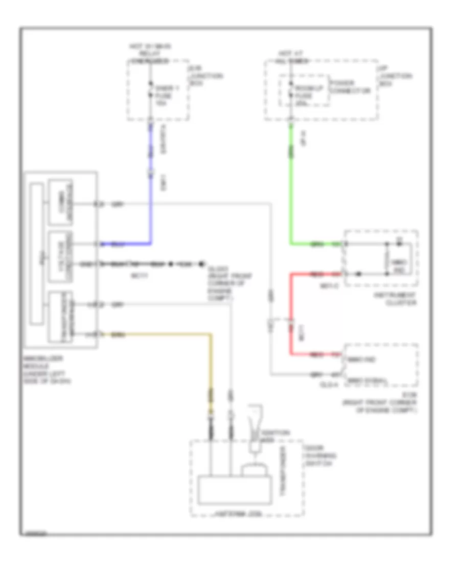
Immobilizer Wiring Diagram, without Smart Key System for Hyundai Veracruz Limited 2012
List of elements for Immobilizer Wiring Diagram, without Smart Key System for Hyundai Veracruz Limited 2012: