ANTI-THEFT
Anti-theft Wiring Diagram (1 of 2) for Infiniti G20 1996

List of elements for Anti-theft Wiring Diagram (1 of 2) for Infiniti G20 1996:
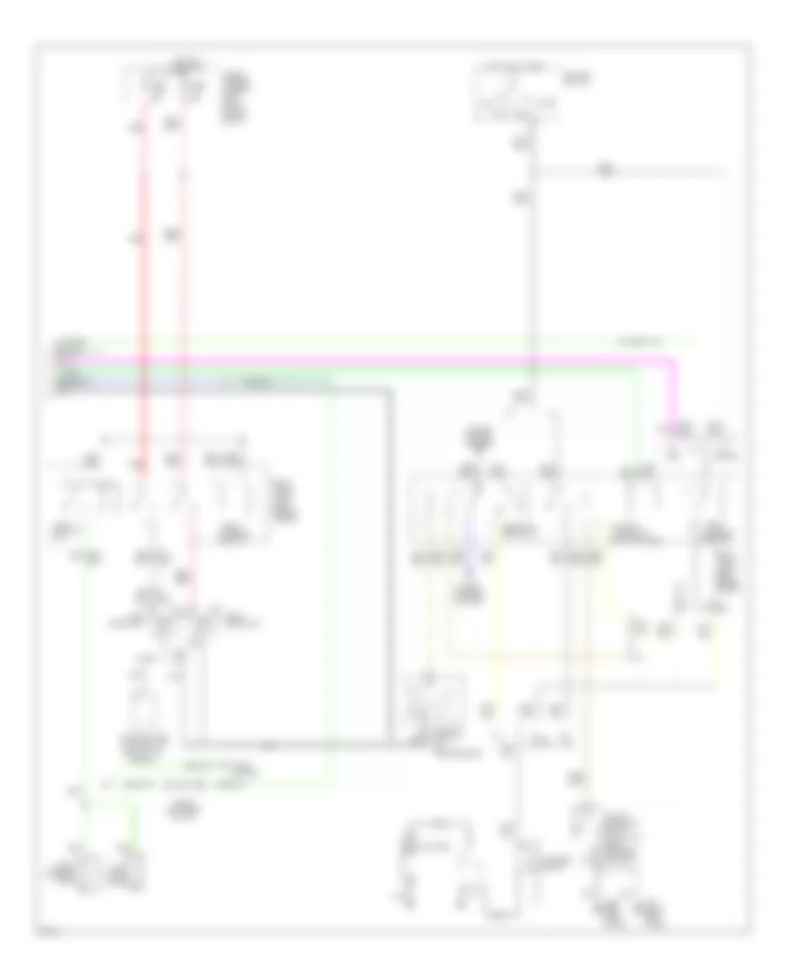
Anti-theft Wiring Diagram (2 of 2) for Infiniti G20 1996
List of elements for Anti-theft Wiring Diagram (2 of 2) for Infiniti G20 1996: