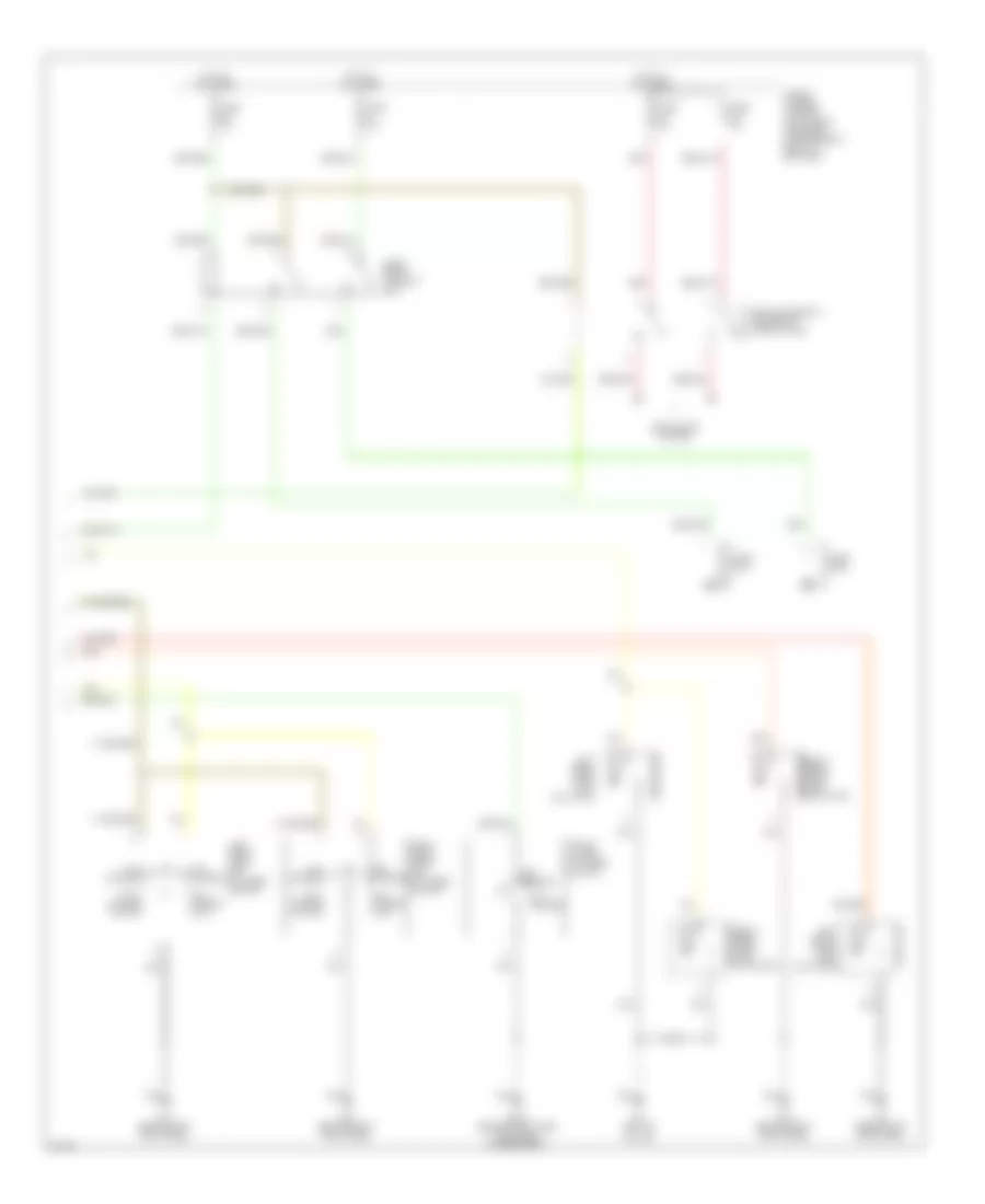
ANTI-THEFT
Anti-theft Wiring Diagram (1 of 2) for Infiniti G20 2002

List of elements for Anti-theft Wiring Diagram (1 of 2) for Infiniti G20 2002:
- Accessory
- B09 (behind right side trim panel of rear seat)
- B110 (behind right side trim panel of rear seat)
- B24 (right "b" pillar)
- B7 (left "b" pillar)
- Battery (c/b)
- Circuit breaker 1 (behind dash, left of fuse block)
- Closed
- Door switches
- Dr door condition sw
- Driver's door sw
- E9 (left front shock tower)
- Fuse & fusible link box (left front of engine compartment, next to battery)
- Fuse 10a
- Fuse 7.5a
- Fuse block (behind dash, left of steering column)
- Fuse d 30a
- Ground
- Hood switch
- Hood switch (left side of engine compt)
- Horn chirp
- Hot at all times
- Hot in acc or on
- Hot in on or start
- Ignition
- Key cylinder sw lock
- Key cylinder sw unlck
- Left front door switch
- Left rear door switch
- M15 (behind left kick panel)
- Open
- Panic alarm output
- Pass door condition sw
- Passenger's door sw
- Pnk
- Rear door condition sw
- Red
- Right front front door door switch switch
- Right rear door switch
- Security indicator
- Security indicator lamp
- Smart entrance control unit (behind dash, left of steering column)
- Trunk key switch
- Trunk room light switch
- Trunk switch
Anti-theft Wiring Diagram (2 of 2) for Infiniti G20 2002
List of elements for Anti-theft Wiring Diagram (2 of 2) for Infiniti G20 2002:
- (left front of engine compartment, next to battery)
- B109 (behind right side trim panel of rear seat)
- B7 (left "b" pillar)
- Full stroke
- Full stroke lock
- Full stroke unlock
- Fuse & fusible link box
- Fuse 10a
- Fuse 15a
- Headlights system
- Horn high
- Horn low
- Horn relay (in relay box)
- Hot at all times
- Left front door key cylinder switch
- Left front door lock actuator
- Left rear door lock actuator
- Locked
- M15 (behind left kick panel)
- M76 (behind right kick panel)
- Mid stroke
- Red
- Right front door key cylinder switch
- Right front door lock actuator
- Right rear door lock actuator
- Trunk lid key cylinder switch
- Unlocked
- Vehicle security lamp relay (in relay box)
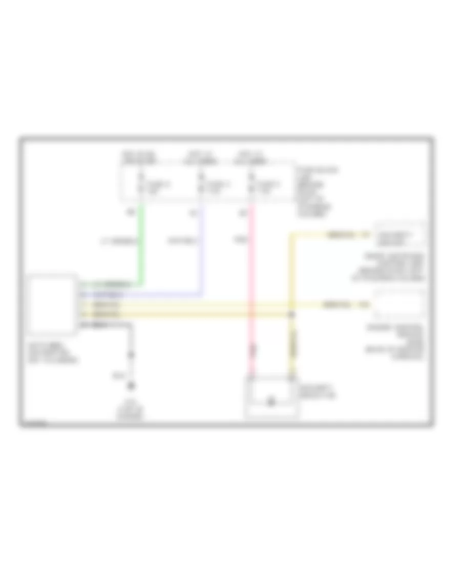
Immobilizer Wiring Diagram (NATS) for Infiniti G20 2002
List of elements for Immobilizer Wiring Diagram (NATS) for Infiniti G20 2002:
- Engine control module (ecm) (base of center console)
- F15 (top of engine)
- Fuse 4 7.5a
- Fuse 5 7.5a
- Fuse 8 10a
- Fuse block (j/b) (behind dash, left of steering column)
- Hot at all times
- Hot in on or start
- Nats immu (on ignition key cylinder)
- Pnk
- Security ind out
- Security indicator
- Smart entrance control unit (behind dash, left of steering column)