ANTI-THEFT
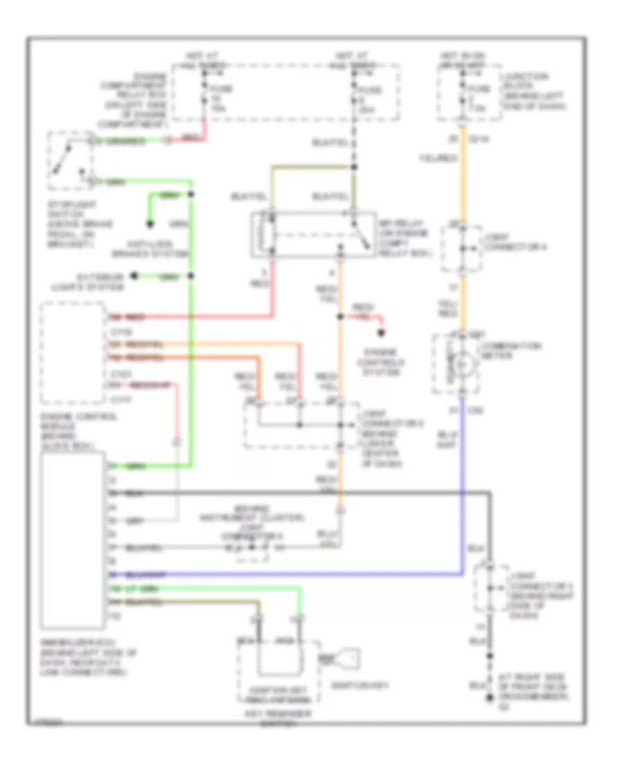
Immobilizer Wiring Diagram, Evolution for Mitsubishi Lancer ES 2003
List of elements for Immobilizer Wiring Diagram, Evolution for Mitsubishi Lancer ES 2003:
- (at right side of front deck crossmember) g3
- (behind instrument cluster) joint connector 5
- All times
- Anti-lock brakes system
- C01
- C02
- C117
- C119
- C121
- C214
- Combination meter
- Engine compartment relay box (on left side of engine compartment)
- Engine control module (behind glove box)
- Engine controls system
- Exterior lights system
- Fuse 15a
- Fuse 20a
- Fuse 7.5a
- Hot at
- Hot in on or start
- Ignition key
- Ignition key ring antenna
- Immobilizer-ecu (behind left side of dash, near data link connectors)
- Joint connector 3 (behind right side of dash)
- Joint connector 4
- Joint connector 6 (behind lower center of dash)
- Junction block (behind left end of dash)
- Key reminder switch
- Mfi relay (on engine compt relay box)
- Nca
- Red
- Security
- Stoplight switch (above brake pedal, on bracket)
 English