ANTI-THEFT
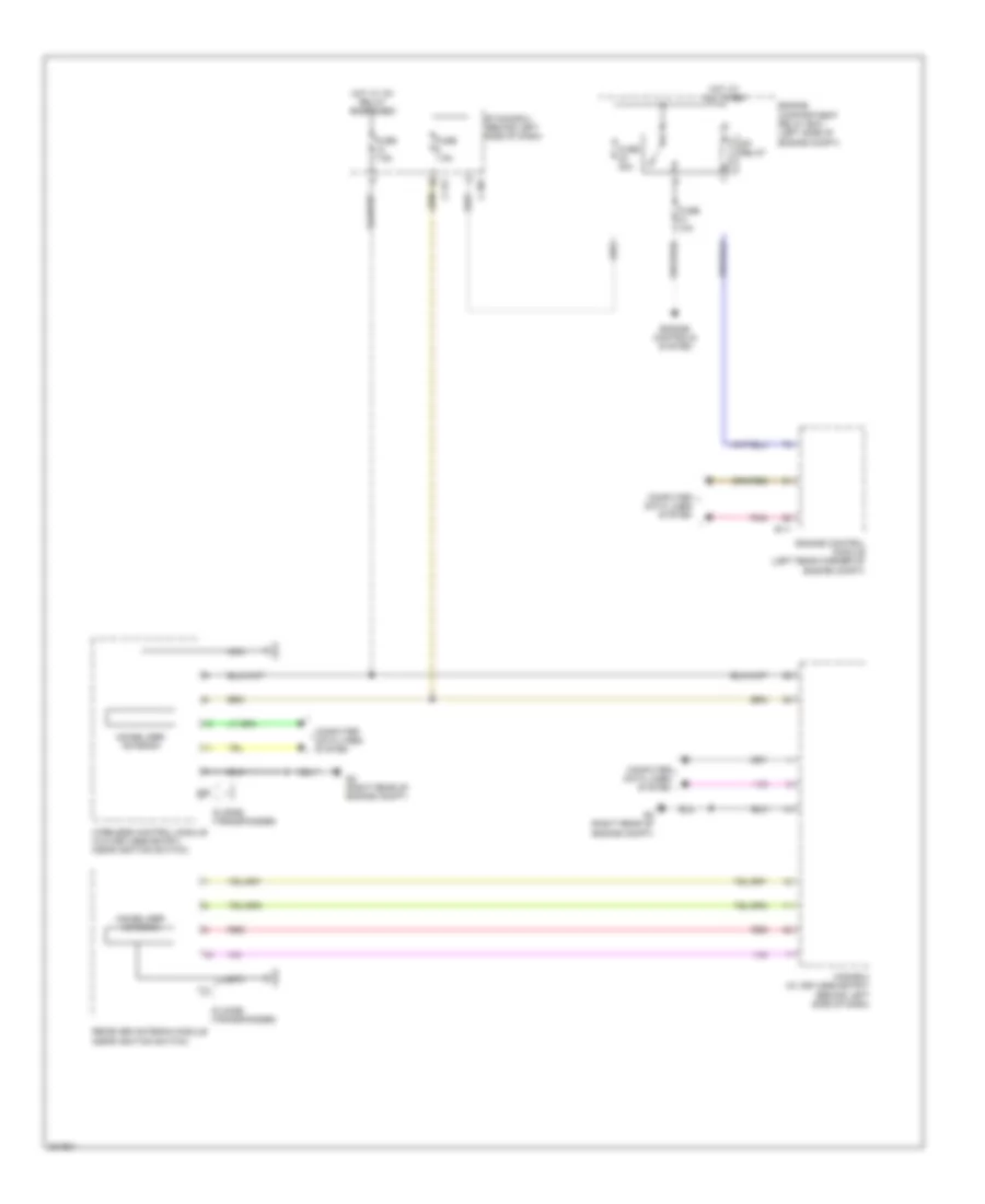
Forced Entry Wiring Diagram for Mitsubishi Outlander ES 2010

List of elements for Forced Entry Wiring Diagram for Mitsubishi Outlander ES 2010:
- (behind left side of dash) joint connector (can1)
- (right rear of engine compt) g2
- A-03
- A-61
- C-301
- C-304
- C-311
- C-312
- C-313
- C-316
- C-317
- C-34
- Can drive circuit
- Can transceiver circuit
- Center panel unit
- Combination meter
- Computer data lines system
- Cpu
- D-12
- D-135
- Engine compartment relay box (left side of engine compt)
- Etacs-ecu (behind left side of dash)
- Exterior lights system
- Fuse 15a
- Fuse 4 10a
- Fuse 7.5a
- Fuse 9 20a
- G1 (right front of engine compt)
- G15 (left side of engine compt)
- G2 (right rear of engine compt)
- G6 (behind left side of dash)
- G7 (left front of roof)
- Hood switch (center front of engine compt)
- Horn relay
- Horns system
- Hot at all times
- Hot w/ ig1 relay energized
- Immobilizer antenna
- Interface circuit
- Keyless entry receiver
- Kos-ecu (w/ keyless entry) (behind left side of dash)
- Lcd (theft-alarm ind)
- Left front door switch (in left "b" pillar)
- Left rear door switch (in left "c" pillar)
- Liftgate switch (center of liftgate)
- Lin cut off control unit
- Nca
- Off
- Pnk
- Receiver antenna module (near ignition switch)
- Red
- Right front door switch (in right "b" pillar)
- Right rear door switch (in right "c" pillar)
- Theft alarm sensor (if equipped)
- Theft alarm siren (w/ theft alarm sensor)
- Theft-alarm horn (right rear corner of engine compt)
- Theft-alarm horn relay (w/o theft- alarm sensor) (in engine room relay box)
- Theft-alarm ind
- Tone alarm
- Turn-signal light control circuit
- Wireless control module (w/o keyless entry) (near ignition switch)
Immobilizer Wiring Diagram for Mitsubishi Outlander ES 2010
List of elements for Immobilizer Wiring Diagram for Mitsubishi Outlander ES 2010:
- B-11
- C-307
- C-317
- Computer data lines system
- Engine compartment relay box (left side of engine compt)
- Engine control module (left rear corner of engine compt)
- Engine controls system
- Etacs-ecu (behind left side of dash)
- Fuse 10a
- Fuse 30a
- Fuse 7.5a
- G2 (right rear of engine compt)
- Hot at all times
- Hot w/ ig1 relay energized
- Id code (transponder)
- Immobilizer antenna
- Kos-ecu (w/ keyless entry) (behind left side of dash)
- Mfi relay
- Nca
- Pnk
- Receiver antenna module (near ignition switch)
- Red
- Wireless control module (w/o keyless entry) (near ignition switch)