ANTI-THEFT
Anti-theft Wiring Diagram (1 of 2) for Nissan Maxima GLE 2001

List of elements for Anti-theft Wiring Diagram (1 of 2) for Nissan Maxima GLE 2001:
- (right "c" pillar)
- 10k
- 12k
- 12l
- Acc
- Alarm output
- Bat (fuse)
- Central lock sw
- Central unlock sw
- Clock (security indicator lamp)
- Door switch (all)
- Door switch (as)
- Dr door switch
- Fuse 10a
- Fuse block (j/b) (behind left side of dash)
- G101 (front of right front fender)
- G200 (left kick panel)
- G202 (left side of dash)
- G203 (right kick panel)
- G305 (right "b" pillar)
- G308 (lower left "b" pillar)
- G407 (center rear of trunk)
- G905
- G905 (right "c" pillar)
- Ground
- H/l out 1
- H/l out 2
- Hood switch
- Hot at all times
- Hot in acc or on
- Hot in on or start
- Ign
- Immobilizer system
- Key cyl lock sw
- Key cyl unlock sw
- Left front door switch
- Left rear door switch
- Lock
- Main power window switch (left door lock switch)
- Pnk
- Right door lock switch
- Right front door switch
- Right rear door switch
- Smart entrance control unit (behind center of dash)
- Theft indicator
- Trunk lid key cylinder switch
- Trunk key switch
- Trunk room lamp switch
- Trunk switch
- Unlock
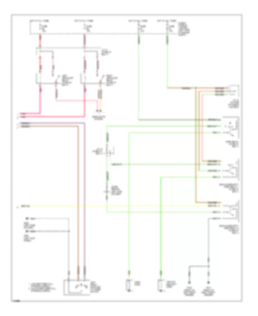
Anti-theft Wiring Diagram (2 of 2) for Nissan Maxima GLE 2001
List of elements for Anti-theft Wiring Diagram (2 of 2) for Nissan Maxima GLE 2001:
- (left kick panel)
- Diode (behind left side of dash)
- Fuse & fusible link box (left side of engine compt)
- Fuse 10a
- Fuse 15a
- G100 (front of left front fender)
- G101 (front of right front fender)
- G200
- G202 (left side of dash)
- Headlights system
- Horn (high)
- Horn relay (in relay box 1)
- Hot at all times
- J/c 10 (in fuse & fusible link box)
- J/c 12 (in relay box 1)
- J/c 14 (in relay box 1)
- Left front door key cylinder switch
- Left headlamp relay (in relay box 1)
- Lock-between full
- Pnk
- Red
- Right headlamp relay (in relay box 1)
- Stroke & normal
- Stroke & normal unlock-between full
- Vehicle security horn
- Vehicle security horn relay 1 (in relay box 1)
- Vehicle security horn relay 2 (in relay box 1)
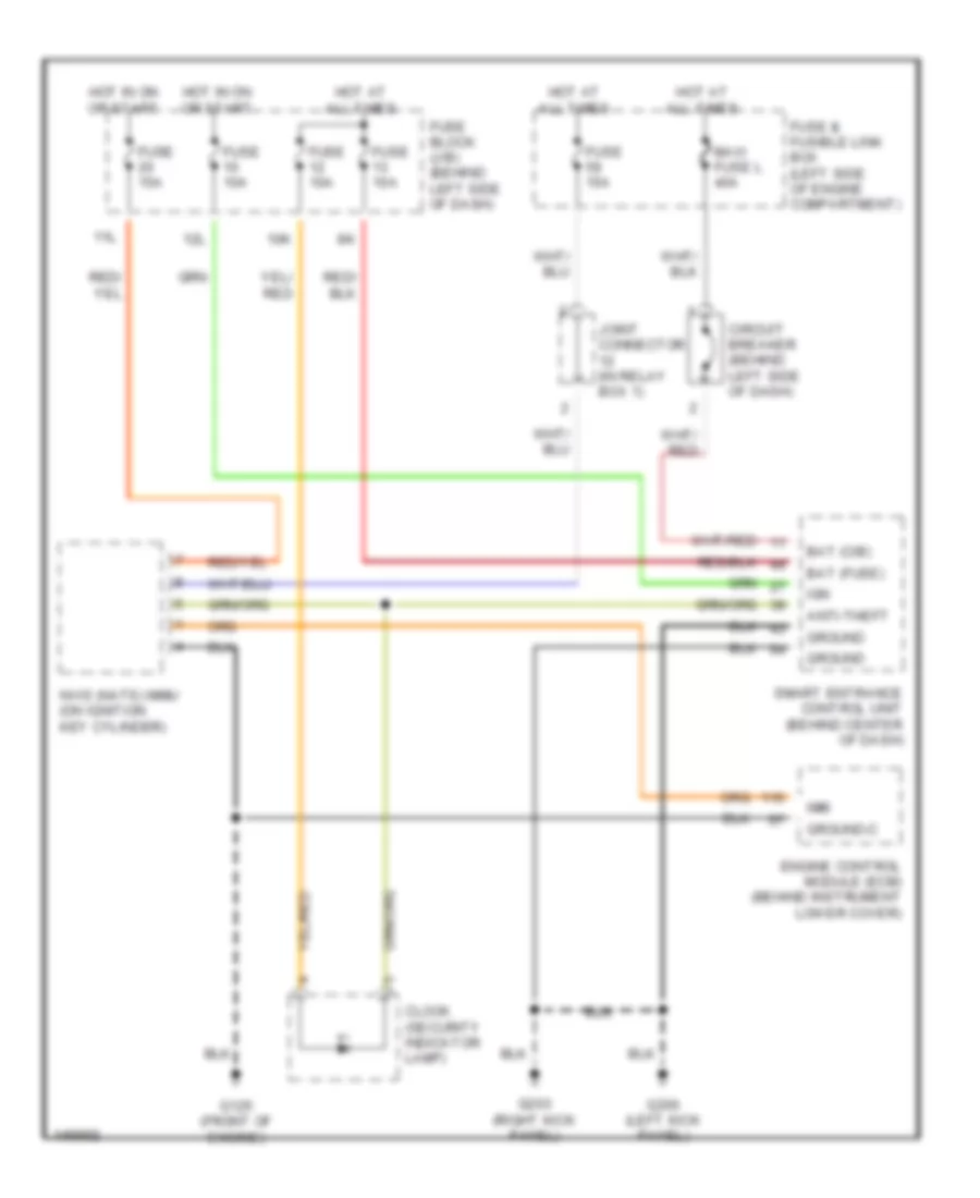
Immobilizer Wiring Diagram (NATS) for Nissan Maxima GLE 2001
List of elements for Immobilizer Wiring Diagram (NATS) for Nissan Maxima GLE 2001:
- 10k
- 11l
- 12l
- Anti-theft
- Bat (c/b)
- Bat (fuse)
- Circuit breaker (behind left side of dash)
- Clock (security indicator lamp)
- Engine control module (ecm) (behind instrument lower cover)
- Fuse & fusible link box (left side of engine compartment)
- Fuse 10a
- Fuse 15a
- Fuse block (j/b) (behind left side of dash)
- G125 (front of engine)
- G200 (left kick panel)
- G203 (right kick panel)
- Ground
- Ground-c
- Hot at all times
- Hot in on or start
- Ign
- Imm
- Joint connector (in relay box 1)
- Maxi fuse l 40a
- Nvis (nats) immu (on ignition key cylinder)
- Smart entrance control unit (behind center of dash)