ANTI-THEFT
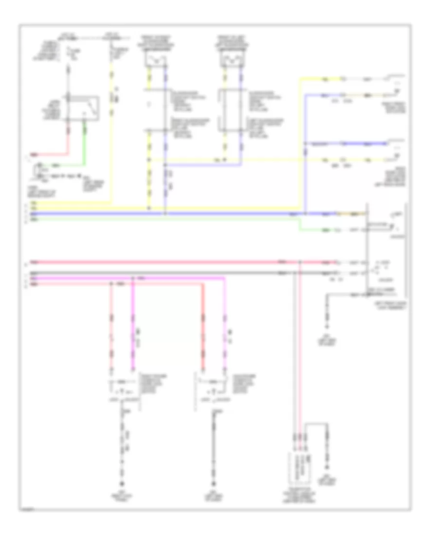
Forced Entry Wiring Diagram (1 of 2) for Nissan NV200 Taxi 2014

List of elements for Forced Entry Wiring Diagram (1 of 2) for Nissan NV200 Taxi 2014:
Forced Entry Wiring Diagram (2 of 2) for Nissan NV200 Taxi 2014
List of elements for Forced Entry Wiring Diagram (2 of 2) for Nissan NV200 Taxi 2014:
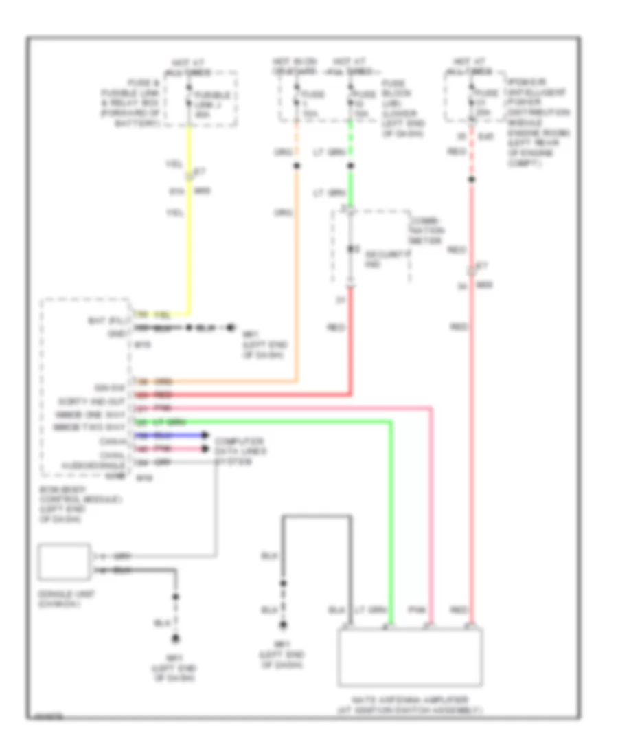
Immobilizer Wiring Diagram for Nissan NV200 Taxi 2014
List of elements for Immobilizer Wiring Diagram for Nissan NV200 Taxi 2014: