ANTI-THEFT
Engine Start Function Wiring Diagram, with Intelligent Key Unit for Nissan Rogue SV 2014

List of elements for Engine Start Function Wiring Diagram, with Intelligent Key Unit for Nissan Rogue SV 2014:
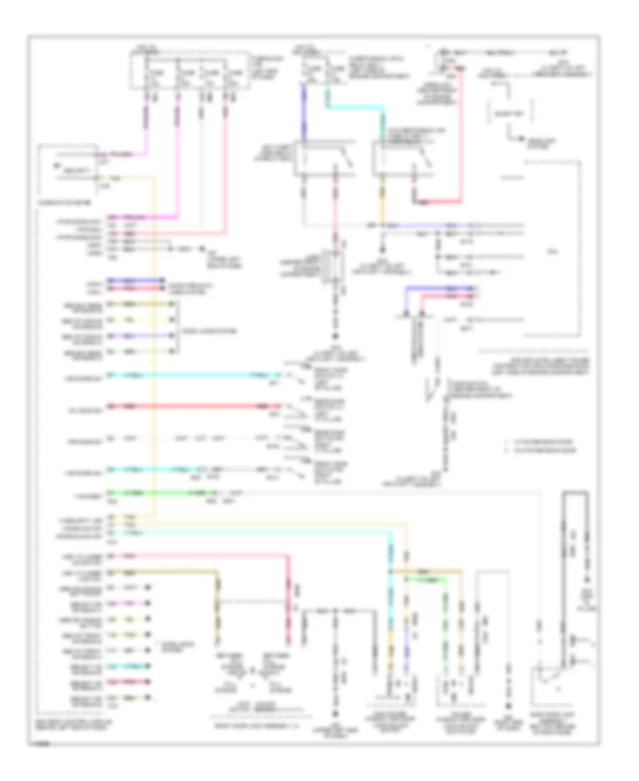
Forced Entry Wiring Diagram for Nissan Rogue SV 2014
List of elements for Forced Entry Wiring Diagram for Nissan Rogue SV 2014:
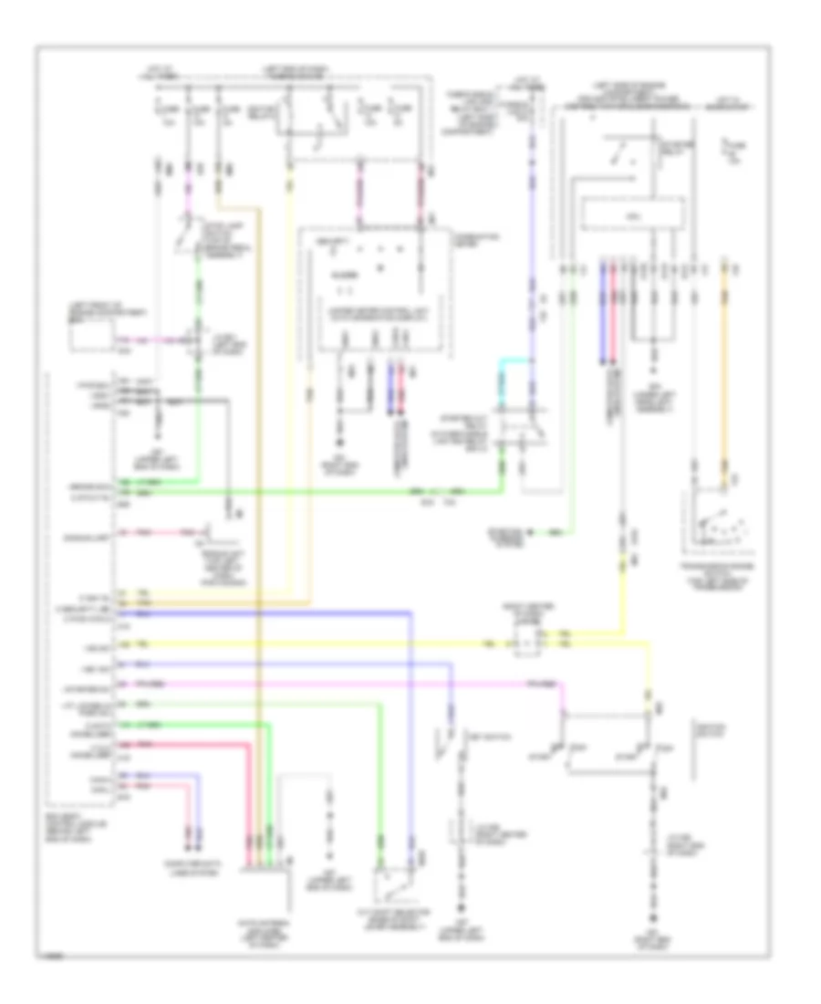
Immobilizer Wiring Diagram, with Intelligent Key Unit for Nissan Rogue SV 2014
List of elements for Immobilizer Wiring Diagram, with Intelligent Key Unit for Nissan Rogue SV 2014:
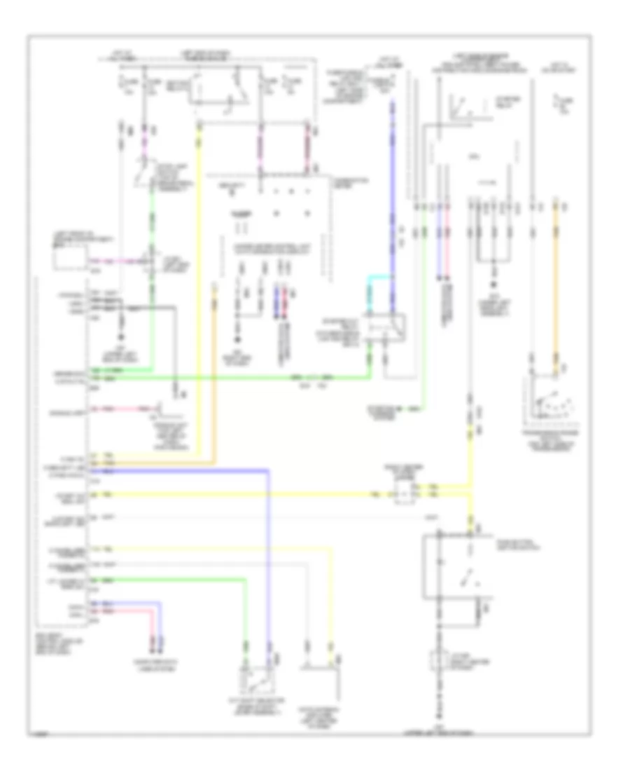
Immobilizer Wiring Diagram, without Intelligent Key Unit for Nissan Rogue SV 2014
List of elements for Immobilizer Wiring Diagram, without Intelligent Key Unit for Nissan Rogue SV 2014: