ANTI-THEFT
Forced Entry Wiring Diagram for Pontiac Bonneville SSEi 1997

List of elements for Forced Entry Wiring Diagram for Pontiac Bonneville SSEi 1997:
- (body harn, 14 cm from lamp control module conn breakout)
- (body harn, 20.5 cm from lamp control module conn breakout)
- (body harn, 31.5 cm from top edge of left kick panel)
- (body harn, 34 cm from ground bolted at center of right kick panel)
- (body harn, 42.5 cm from remote fucntion actuator module)
- (body harn, 9 cm from left edge of i/p cross-channel)
- (buic) (pont)
- (buick)
- (i/p harn, buick: 10 cm from breakout to 116-pin black conn below right side of i/p, near center; pontiac: 12 cm from i/p compt lamp breakout)
- 1995 vftc c
- Battery
- D b
- Data line
- Data link connector (behind i/p, right of steering column)
- Door lock input
- Door unlock input
- Door unlock input/output
- E10
- E11
- E12
- E13
- E16
- Exterior lamp input
- F10
- F13
- F16
- F4
- G200 (left kick panel)
- G200 (left kickpad)
- Ground
- Headlamps alarm output
- Horn relay control
- Horns system (horn relay)
- Hot at all times
- Indicator control
- Junction connector c340 (left front door sill, taped to harness)
- Key unlock input
- Lamp control module (center of i/p)
- Left front door lock lock
- Left front door latch switch
- Left front door lock cylinder switch
- Left front door open in
- Left rear door latch switch
- Multi-function alarm, lock and lighting module (behind right side of i/p)
- Passenger door jamb
- Passkey circuit
- Relay center (right kick panel)
- Remote function actuator module (behind right
- Right front door lock lock
- Right front door latch switch
- Right front door lock cylinder switch
- Right rear door latch assembly
- S210
- S218
- S225
- S248
- S251
- S252
- S278
- S289
- S291
- S310
- S603
- Side of i/p)
- Switch
- Tamper switch (buick)
- Tamper switch input
- Trunk lid tamper switch (near latch)
- Trunk/rel/pwr ant/rac lks fuse 2 15a
- Unlock
- Unlock switch
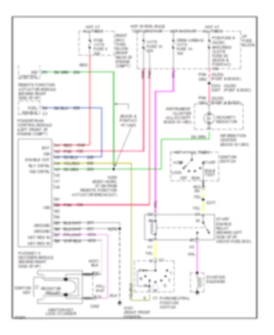
Pass-Key Wiring Diagram for Pontiac Bonneville SSEi 1997
List of elements for Pass-Key Wiring Diagram for Pontiac Bonneville SSEi 1997:
- (buick & pontiac w/ ua6)
- (olds) (pont & buic)
- Accy
- Bat
- Bulb test
- C202
- Crnk airbag/ vats fuse 1a 10a
- E12
- E13
- Enable out
- Enable relay (behind left side of i/p, above fuse box)
- Fuel enable
- G101 (right front fender)
- Ground
- Hot at all times
- Hot in run, bulb
- Hot in start
- I/p fuse block
- Ign
- Ignition key
- Ignition key lock cylinder
- Ignition switch
- Ind cntrl
- Ind control
- Information center (buick w/ ub3)
- Instrument cluster (all except buick w/ ub3)
- Key res in
- Lock
- Misc/rdo/ clstr fuse 9c (buick & pontiac) 10a
- Nca
- Off
- Park/neutral position switch
- Passkey ii decoder module (behind right side of i/p)
- Pcm fuse 8 (olds)
- Pcm/ vats fuse 4 20a
- Pnk
- Powertrain control module (left front of engine compt)
- Red
- Remote function actuator module (behind right side of i/p)
- Resistor pellet
- Right maxi fuse block (right rear of engine compt)
- Rly cntrl
- Run
- S217
- S233 s207
- S266 (body harn, 37 cm from remote function actuator breakout)
- S270
- Security indicator
- Start
- Starter solenoid
- Test or start
- Vats fuse 1a 10a