ANTI-THEFT
Forced Entry Wiring Diagram for Suzuki Grand Vitara Limited 2011

List of elements for Forced Entry Wiring Diagram for Suzuki Grand Vitara Limited 2011:
- (behind left end of dash) junction connector g82
- (on steering column assembly) g17
- Body control module (bcm) (behind left side of dash)
- Can
- Combination meter
- Computer data lines system
- Cpu
- Diode 3 (behind right kick panel)
- Dome fuse 10a
- Door ind
- Door lock fuse 20a
- Driver side power door lock main switch
- Exterior lights system
- G03
- G07
- G08
- G18
- G30
- G31
- G32
- G72
- High
- Horns system
- Hot at all times
- Hot in on or start
- Interior lights system
- J01
- J09
- J16
- J21
- Joint connector g76 (behind left side of dash)
- Junction block (j/b) (behind left side of dash)
- Junction connector l22 (in right "d" pillar)
- Keyless entry receiver (if equipped) (behind lower center of dash)
- L07
- L08
- L09
- L13
- L27
- L31
- L37
- L42
- Left front door switch (on left "b" pillar)
- Left front power door lock actuator
- Left rear door lock motor (in left rear door)
- Left rear door switch (on left "c" pillar)
- Lock
- Low
- Main switch (key switch)
- Meter fuse 10a
- O01
- Off
- Passenger side door lock sub switch
- Pnk
- Rear end door lock motor (at lower left side of rear door)
- Rear end door switch (base of left "d" pillar)
- Red
- Right front door switch (on right "b" pillar)
- Right front power door lock actuator
- Right rear door lock motor (in right rear door)
- Right rear door switch (on right "c" pillar)
- Security option
- Un- lock
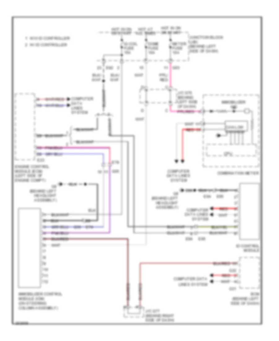
Immobilizer Wiring Diagram for Suzuki Grand Vitara Limited 2011
List of elements for Immobilizer Wiring Diagram for Suzuki Grand Vitara Limited 2011:
- Bcm (behind left side of dash)
- Can low can high
- Combination meter
- Computer data
- Computer data lines system
- Cpu
- Dome fuse 10a
- E23
- E74
- E78
- E82
- E94
- E95
- Engine control module (ecm) (left side of engine compt)
- G03
- G05
- G31
- G32
- G36
- G8 (behind left headlight assembly)
- Hot at all times
- Hot in on or start
- Id control module
- Ig coil fuse 15a
- Immobilizer control module (icm) (on steering column assembly)
- Immobilizer ind
- J/c g76 (behind left side of dash)
- J/c g77 (behind right side of dash)
- Junction block (j/b) (behind left side of dash)
- Lines system
- Meter fuse 10a
- Red
- W/ id controller
- W/o id controller