ANTI-THEFT
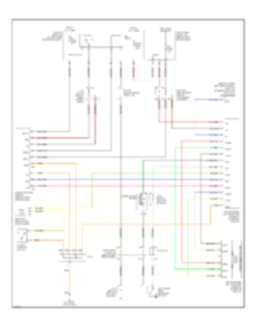
Forced Entry Wiring Diagram (1 of 3) for Toyota Sequoia SR5 2004

List of elements for Forced Entry Wiring Diagram (1 of 3) for Toyota Sequoia SR5 2004:
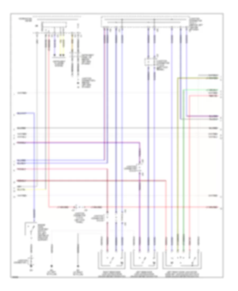
Forced Entry Wiring Diagram (2 of 3) for Toyota Sequoia SR5 2004
List of elements for Forced Entry Wiring Diagram (2 of 3) for Toyota Sequoia SR5 2004:
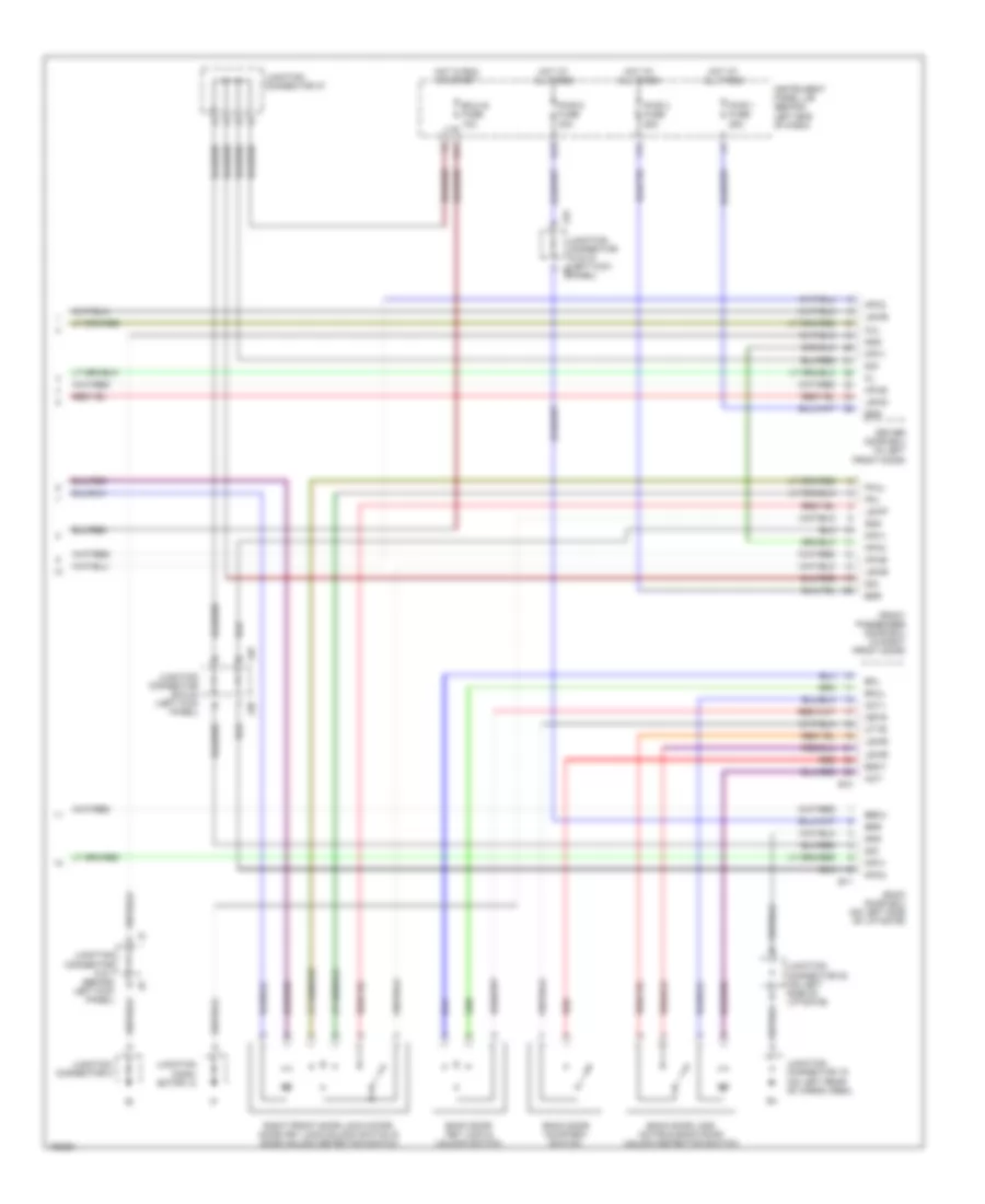
Forced Entry Wiring Diagram (3 of 3) for Toyota Sequoia SR5 2004
List of elements for Forced Entry Wiring Diagram (3 of 3) for Toyota Sequoia SR5 2004:
Immobilizer Wiring Diagram for Toyota Sequoia SR5 2004
List of elements for Immobilizer Wiring Diagram for Toyota Sequoia SR5 2004: