ANTI-THEFT
Forced Entry Wiring Diagram for Volvo C30 T-5 2012

List of elements for Forced Entry Wiring Diagram for Volvo C30 T-5 2012:
- (base of left "a" pillar) g115
- (base of right "a" pillar) g10
- (base of right "a" pillar) g116
- 64/41
- 64/43
- 64/48
- A11
- A12
- A15
- A18
- A28
- Ajar sw
- B28
- C24
- C31
- Cem
- Central electronic module (cem) (right side of dash)
- Computer data lines system
- D10
- Defogger system
- Driver's door lock unit (rear of driver's front door)
- Driver's door module (ddm) (center of driver's front door)
- E21
- E22
- E36
- Engine compartment distribution box (left side of engine compt)
- F15
- F18
- F19
- F21
- F24
- F30
- Fuse f18 40a
- Fuse f4 60a
- Fuse f56 10a
- Fuse f82 25a
- Fuse f83 25a
- G11 (left rear corner of trunk)
- G114 (on left front strut tower)
- G19
- Glass break sensor
- H17
- H21
- Heated rear window
- Hood alarm contact (at front of engine compartment)
- Hot at all times
- Lock sw
- Passenger's door lock unit (rear of passenger's front door)
- Passenger's door module (pdm) (center of passenger's front door)
- Power windows system
- Siren control module (scm) (right front wheelwell)
- Solar sensor, twilight sensor & indicator alarm (on top center of dash)
- Trunk lid/tailgate lock unit (c30: center rear of trunk lid/tailgate)
- Ultrasonic sensor
- Wiper/washer system
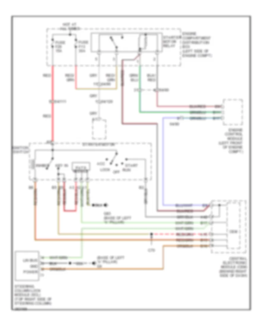
Immobilizer Wiring Diagram for Volvo C30 T-5 2012
List of elements for Immobilizer Wiring Diagram for Volvo C30 T-5 2012:
- (base of left "a" pillar) g6
- 64/111
- 64/120
- 64/90
- A15
- A42
- Acc
- B10
- B11
- B13
- B17
- C70
- Cem
- Central electronic module (cem) (behind right side of dash)
- Engine compartment distribution box (left side of engine compt)
- Engine control module (left front of engine compt)
- Fuse f13 30a
- Fuse f26 15a
- G83 (base of left "a" pillar)
- Gnd
- Hot at all times
- Ignition switch
- Inhibit
- Key in
- Lin bus
- Lock
- Off
- Pats module
- Power
- Red
- Run
- Start
- Starter motor
- Starter motor relay
- Steering column lock module (scl) (top right side of steering column)