ANTI-THEFT
Forced Entry Wiring Diagram for Volvo S40 T-5 2005

List of elements for Forced Entry Wiring Diagram for Volvo S40 T-5 2005:
- (at left kick panel) g115
- (at right kick panel) g10
- (at right kick panel) g116
- (below driver's seat near rocker panel) g66
- (below passenger's seat near rocker panel) g67
- A12
- A14
- A15
- A18
- Ajar sw
- Ceiling light switch unit
- Central electronic module (cem) (behind right side of dash)
- Computer data lines system
- Driver's door lock unit (at rear of left front doors)
- Driver's door module (in driver's door)
- Engine compartment distribution box (left side of engine compt)
- Front mass movement sensor (center of roof)
- Fuse 10a
- Fuse 25a
- Fuse 40a
- Fuse 60a
- G114 (on left front strut tower)
- G66 (below driver's seat near rocker panel)
- Hood alarm contact (at front of engine compt)
- Hot at all times
- Left rear door lock unit (at rear of left rear door)
- Left rear door module (in left rear door)
- Lock sw
- Passenger's door lock unit (at rear of right front door)
- Passenger's door module (in front passenger's door)
- Rear mass movement sensor (center rear of roof)
- Right rear door lock unit (at rear of right rear door)
- Right rear door module (in right rear door)
- Siren (scm) (at right rear of engine compt)
- Solar sensor taillight sensor & indicator alarm (on top center of dash)
- Trunk lid/ tailgate lock unit (center rear of trunk)
- V50
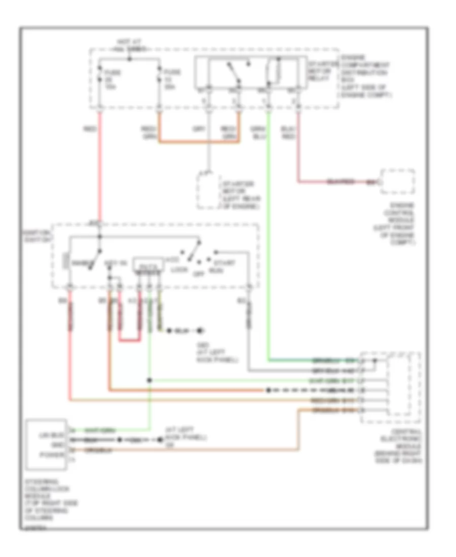
Immobilizer Wiring Diagram for Volvo S40 T-5 2005
List of elements for Immobilizer Wiring Diagram for Volvo S40 T-5 2005:
- (at left kick panel) g6
- A15
- A42
- Acc
- B10
- B13
- B17
- Central electronic module (behind right side of dash)
- Engine compartment distribution box (left side of engine compt)
- Engine control module (left front of engine compt)
- Fuse 15a
- Fuse 30a
- G83 (at left kick panel)
- Gnd
- Hot at all times
- Ignition switch
- Inhibit
- Key in
- Lin bus
- Lock
- Nca
- Off
- Pats module
- Power
- Red
- Run
- Start
- Starter motor (left rear of engine)
- Starter motor relay
- Steering column lock module (top right side of steering column)