ANTI-THEFT
Anti-theft Alarm Wiring Diagram for Volvo V70 R 1998

List of elements for Anti-theft Alarm Wiring Diagram for Volvo V70 R 1998:
- 15i-rail connector
- A/c system
- A10
- A11
- A12
- A13
- A14
- A15
- A16
- A17
- A18
- A19
- A20
- A21
- A22
- A23
- A24
- A25
- A26
- Alarm horn
- Alarm horn relay (in central electrical unit, position 202)
- Alarm siren
- Alarm/ electronic immobilizer indicator
- B10
- B11
- B12
- B13
- B14
- B15
- B16
- B17
- B18
- B19
- B20
- Bonnet alarm switch (front of eng compt)
- C10
- Car tilt sensor (on right rear corner of vehicle)
- Central electrical unit
- Central locking/ anti-theft alarm control module (behind lower left end of dash)
- Central locking/alarm remote control unit (behind upper left side of dash)
- Data link connector (on center console, near shift lever)
- Door locks system
- Electronic climate control module (behind center of dash)
- Exterior lights system (turn signal)
- Fuse c13 15a
- Fuse c18 10a
- Fuse c2 10a
- Fuse c29 10a
- Fuse c6 20a
- G102 (left front strut tower)
- G102 strut tower) (left front
- G404 (left rear side of trunk)
- G900 (left "a" pillar)
- G901 (right "a" pillar)
- Glass breakage sensor (behind right side of dash)
- Hot at all times
- Hot w/ overload relay 106 energized
- Ignition switch
- Instrument cluster system
- Key in ignition switch
- Left movement detector (left "b" pillar)
- Left rear side window alarm lead (v70 only)
- Microphone
- Nca
- Power ground rail (in central electrical unit)
- Rear heated window element
- Red
- Right movement detector (right "b" pillar)
- Right rear side window alarm lead (v70 only)
- Solid state
- Stater motor relay (in eng compt relay/fuse box position 3)
- W/ ecc
- W/o ecc
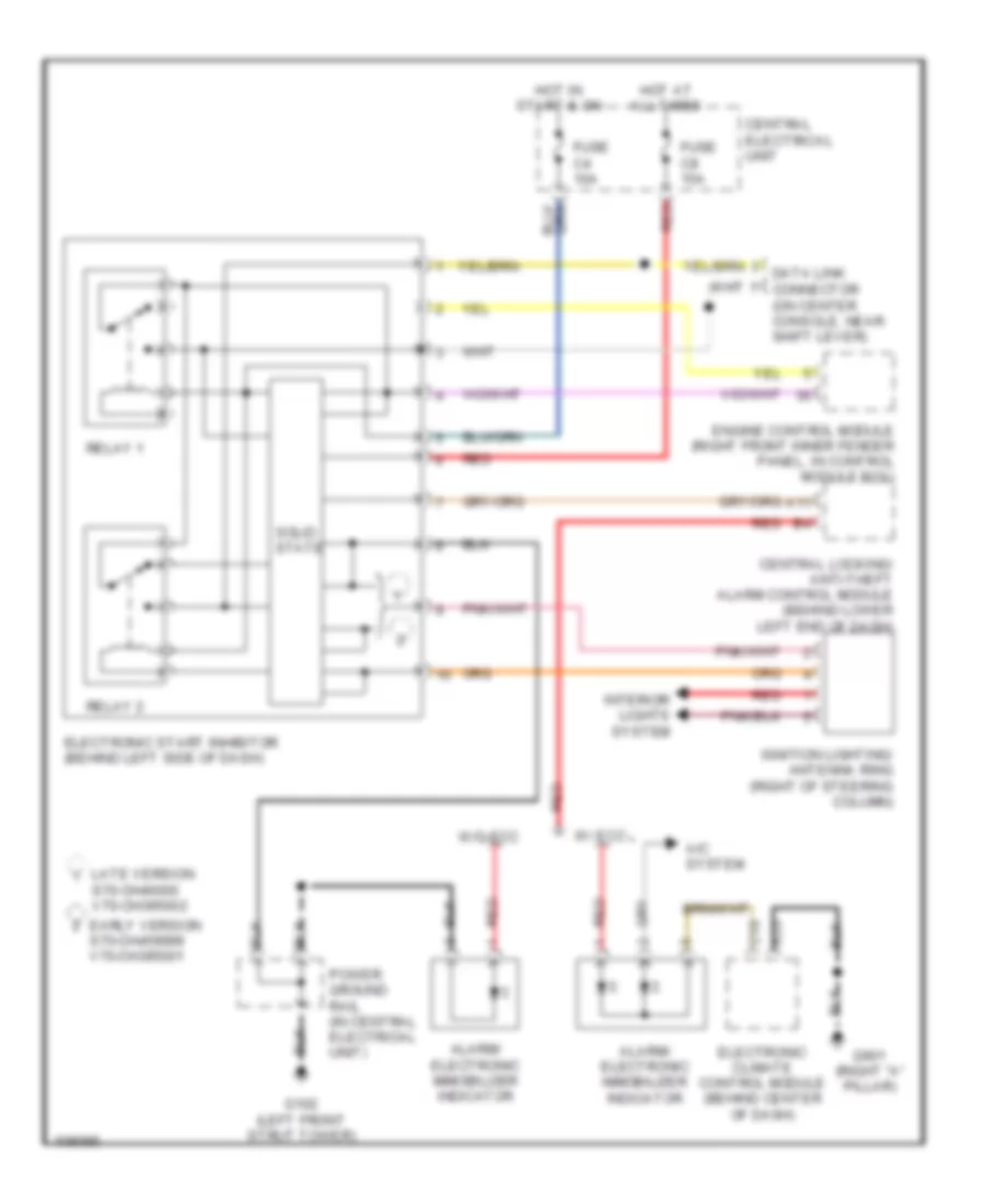
Immobilizer Wiring Diagram for Volvo V70 R 1998
List of elements for Immobilizer Wiring Diagram for Volvo V70 R 1998:
- A/c system
- A11
- A23
- Alarm/ electronic immobilizer indicator
- C10
- Central electrical unit
- Central locking/ anti-theft alarm control module (behind lower left end of dash)
- Early version s70-ch459999 v70-ch395001
- Electronic climate control module (behind center of dash)
- Electronic start inhibitor (behind left side of dash)
- Engine control module (right front inner fender panel, in control module box)
- Fuse c4 10a
- Fuse c8 15a
- G102 (left front strut tower)
- G901 (right "a" pillar)
- Hot at all times
- Hot in start & on
- Ignition lighting/ antenna ring (right of steering column)
- Interior lights system
- Late version s70-ch46000 v70-ch395002
- Power ground rail (in central electrical unit)
- Red
- Relay 1
- Relay 2
- Solid state
- W/ ecc
- W/o ecc