ANTI-THEFT
Forced Entry Wiring Diagram for Volvo XC90 2011

List of elements for Forced Entry Wiring Diagram for Volvo XC90 2011:
- (at left rear of cargo compt) g72
- (right side of engine compt, on strut tower) g94
- 54/10
- 54/11
- 54/13
- 54/20
- 54/21
- 54/3.1
- 54/40d
- 54/43
- A10
- A11
- A12
- A13
- B25
- C12
- C13
- C14
- Central electronic module (behind left side of dash)
- Climate control module
- Computer data lines system
- D26
- D29
- D31
- D33
- D34
- D35
- D42
- D49
- D50
- Driver/passenger door module (ddm/pdm) (in driver's door)
- Exterior lights system
- Front mass movement sensor (mms) (center front of roof)
- Fuse c12 10a
- Fuse c13 15a
- Fuse e1 60a
- Fuse e4 50a
- Fuse e5 50a
- Fuse f8 5a
- G46 (on left rear seat riser)
- G67 (on right front seat riser)
- G93 (left side of engine compt, on strut tower)
- G98 (at front center of headliner)
- Hood alarm contact (at front of engine compt)
- Hot at all times
- Inclination sensor module (left rear of vehicle)
- Key
- Left front door lock unit (rear left front door)
- Left rear door lock unit (rear of left rear door)
- Lock
- Lock right front door lock unit (rear of right front door)
- Main fuses (next to battery, in cargo compt)
- Passenger compartment fuse box (at left end of dash)
- Passenger/driver door module (pdm/ddm) (in front passenger's door)
- Pnk
- Rear electronic module (at left rear corner of cargo compt)
- Rear mass movement sensor (mms) (center rear of roof)
- Red
- Reduced alarm switch
- Remote control antenna
- Right rear door lock unit (rear of right rear door)
- Siren control module (right front wheelwell)
- Solar sensor, twilight sensor & indicator alarm (at top center of dash)
- Sun roof module (srm) (forward of sun roof opening)
- Tailgate lock unit (center of tailgate)
- Unlock
- Upper electronic module (uem) (rearward of roof console)
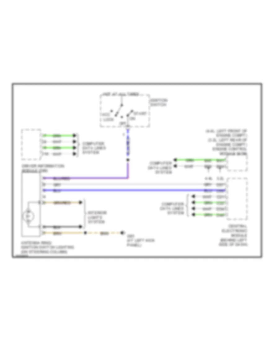
Immobilizer Wiring Diagram for Volvo XC90 2011
List of elements for Immobilizer Wiring Diagram for Volvo XC90 2011:
- (4.4l: left front of engine compt) (3.2l: left rear of engine compt) engine control module (ecm)
- 3.2l
- 4.4l
- Acc
- Antenna ring/ ignition switch lighting (on steering column)
- B41
- B45
- B54
- B58
- C21
- C22
- Central electronic module (behind left side of dash)
- Computer data lines system
- D34
- D49
- D56
- D57
- Driver information module (dim)
- G83 (at left kick panel)
- Hot at all times
- Ignition switch
- Interior lights system
- Lock
- Off
- Start
 English