
Audi 90 CS Quattro 1994 - 1994 ENGINE PERFORMANCE Self-Diagnostics - 90, 100 & Cabriolet
Audi 90 CS Quattro 1994 - INTRODUCTION
If no faults were found during preliminary inspection, proceed with self-diagnostics. If no trouble codes or only pass codes are present after entering self-diagnostics, proceed to TESTS W/O CODES article in the ENGINE PERFORMANCE Section for diagnosis by symptom (i.e. ROUGH IDLE, NO START, etc.).
Audi 90 CS Quattro 1994 - SELF-DIAGNOSTIC SYSTEM STORED CODES
Electronic Control Module (ECM) can identify malfunctions and store them in memory in the form of a code. Codes are stored until memory is erased. If battery cable or ECM connector is disconnected, codes are erased.
Audi 90 CS Quattro 1994 - MALFUNCTION INDICATOR LIGHT (MIL)
When ignition is turned on, MIL should come on. When engine is started, MIL should turn off. If MIL does not turn off after engine is started, or if MIL comes on while driving, retrieve codes. See RETRIEVING CODES.
Audi 90 CS Quattro 1994 - ECM VERSIONS "A" & "B"
Due to a production change, Cabriolet and 90 models are equipped with one of 2 different ECMs. Early version ECM can be identified by part number 4AO 906 266 A/AA/AB (MMS 200), referred to as ECM "A" in this article. Later version ECM can be identified by part number 8AO 906 266 B (MMS 300), referred to as ECM "B" in this article. 100 models use ECM "A".
Audi 90 CS Quattro 1994 - HARD FAILURES
Hard failures (also called static malfunctions) cause MIL to come on and a code to set in ECM memory. A code that sets as a result of a hard failure will not be erased automatically when the problem is eliminated. These codes must be erased manually.
Audi 90 CS Quattro 1994 - INTERMITTENT FAILURES
When an intermittent failure occurs, MIL comes on and code sets. Scan tester displays "SP" to identify code as sporadic (intermittent). If fault does not recur within 50 engine starts, code will automatically be erased. Intermittent failures may be caused by problems with a sensor, connector or wiring. See TESTS W/O CODES article in the ENGINE PERFORMANCE Section.
Audi 90 CS Quattro 1994 - ENTERING SELF-DIAGNOSTICS
NOTE: Before entering self-diagnostics, ensure fuses are okay and fuel pump relay is okay. Press scan tester HELP button for additional trouble shooting tips or operating information. Press arrow button to step through program sequence. When prompted by scan tester, press appropriate buttons to input information, then press "Q" button to enter input.
- Turn ignition off. Remove cover from fuse/relay block under left side of instrument panel. See Fig. 1 or Fig. 2 . Connect Black connector of Scan Tester (VAG 1551) to Black connector of Data Link Connector (DLC).
- Idle engine (if engine will not start, operate starter for at least 5 seconds and leave ignition on). If no information is displayed on scan tester, check voltage supply to Black DLC. See CHECKING DATA LINK CONNECTORS. If scan tester alternately displays 1 - RAPID DATA TRANSFER and 2 - BLINK CODE OUTPUT, connect White connector of VAG 1551 to White connector of DLC. Blue connector is not used.
- Press PRINT button to turn on printer. Indicator light on PRINT button should come on. Press "1" button to select RAPID DATA TRANSFER function. Enter "01" to select ENGINE ELECTRONICS function.
- If any of the following messages are displayed, go to NO COMMUNICATION BETWEEN ECM & SCAN TESTER.
- CONTROL MODULE DOES NOT ANSWER
- COMMUNICATION MALFUNCTION
- L- Or K-CONNECTION DOES NOT SWITCH TO GROUND/POSITIVE.
- If SCAN TOOL SENDS ADDRESS WORD 01 is displayed, wait for ECM identification and coding information to be displayed. Ensure information displayed matches vehicle. See ECM ENCODING.
- Push right arrow button. Function is now ready to be selected. To select function, input appropriate 2-digit code and press enter. For list of available functions, see SELECTABLE FUNCTIONS table. To print a list of available functions, press HELP button. After selecting function, go to appropriate part of this article. When finished viewing displayed data, select function 06 to end output of data.
Audi 90 CS Quattro 1994 SELECTABLE FUNCTIONS
Input Number Function 02 Read DTC Memory 03 Output Diagnostic Test Mode 04 Engine Basic Setting 05 Erase DTC Memory 06 End Data Transfer 07 ECM Encoding 08 Reading Measuring Block 09 Reading Individual Measuring Values 10 (1) Adaptive Learning
(1) Applies only to ECM "B".
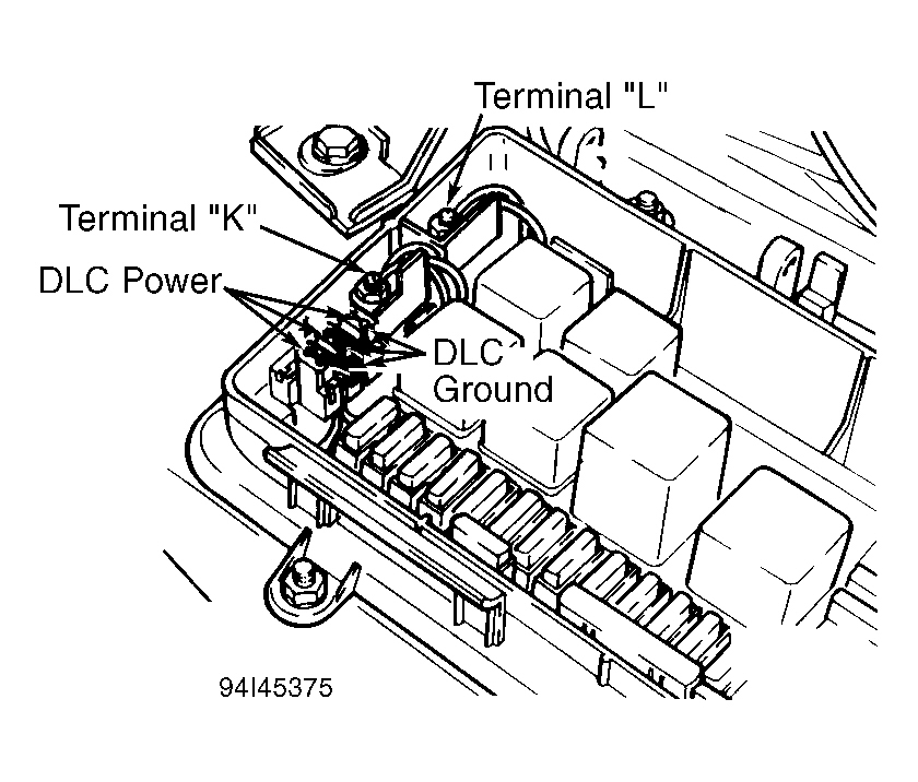
Fig. 2: Audi 90 CS Quattro 1994 - Component Locations - Identifying Data Link Connectors (DLC) (100)

Audi 90 CS Quattro 1994 - NO COMMUNICATION BETWEEN ECM & SCAN TESTER Control Module Does Not Answer
Press HELP button to generate a list of possible malfunction causes. Check DLC wiring. See CHECKING DLC WIRING. Check for defective ECM by performing diagnostic procedure for Code 65535. After eliminating cause, enter address word "01" to select ENGINE ELECTRONICS.
Audi 90 CS Quattro 1994 - Communication Malfunction
Check for defective ECM by performing diagnostic procedure for Code 65535.
Audi 90 CS Quattro 1994 - L- Or K-Connection Does Not Switch To Ground/Positive
Press HELP button to generate a list of possible malfunction causes. After eliminating cause, enter address word "01" to select ENGINE ELECTRONICS.
Audi 90 CS Quattro 1994 - CHECKING DLC WIRING
Black DLC is for scan tester power and ground circuits. White DLC is for scan tester rapid data transfer circuits. All systems that can be monitored with a scan tester (ECM, automatic transmission, ABS, etc.) are monitored through the same White DLC. Rapid data transfer circuits for all systems are connected in parallel to terminals "K" and "L", which serve as common junction blocks. See Fig. 1 or Fig. 2 . Ground terminal of White DLC is connected to terminal "L". Power terminal of White DLC is connected to terminal "K".
Audi 90 CS Quattro 1994 - Black DLC
Ensure DLC ground terminal is grounded. See Fig. 1 or Fig. 2 . Battery voltage should be present at DLC power terminal. If conditions are not as specified, repair wiring or replace fuse as necessary.
Audi 90 CS Quattro 1994 - White DLC
- Disconnect all wires from terminals "K" and "L", noting from which terminals wires are disconnected. See Fig. 1 or Fig. 2 . Check continuity between power terminal of White DLC connector and terminal "L", and between ground terminal of White DLC connector and terminal "K". If there is no continuity, repair wiring.
- If there is continuity, check continuity between:
- ECM terminal C13 and appropriate wire at terminal "L"
- ECM terminal C12 and appropriate wire at terminal "K".
- If there is no continuity, repair wiring. If there is continuity, connect wires for ECM rapid data transfer to terminals "K" and "L". Attempt to enter ENGINE ELECTRONICS (address word "01"). If ENGINE ELECTRONICS cannot be entered, replace ECM.
- If ENGINE ELECTRONICS can be entered, check wiring between terminals "K" and "L" and control units for all other systems. If wiring is okay, replace appropriate control unit.
Audi 90 CS Quattro 1994 - RETRIEVING CODES Using Malfunction Indicator Light (MIL)
- Turn ignition on. Remove cover from fuse/relay block under left side of instrument panel. See Fig. 1 or Fig. 2 . Connect Jumper Cable (357 971 514E) to Data Link Connectors (DLC). Black end of jumper cable attaches to Black DLC; White end of cable attaches to White DLC; Blue DLC is not used.
- Leave jumper cables attached for 5 seconds, until MIL begins to blink. Remove jumper cable. Allow on-board diagnostic code retrieval procedure to run until Code 4444 (no faults indicated) or Code 0000 (end of output) appears. To end code retrieval procedure, reconnect jumper cable to DLC or turn ignition off.
NOTE: Retrieve codes with engine running if possible. Before retrieving codes, initiate output DTM, perform engine basic setting and read measuring block values. Before testing system performance or replacing components, check for poor connection at ground wires attached to intake manifold, right engine mount and battery negative terminal.
Audi 90 CS Quattro 1994 - Using San Tester (VAG 1551)
Enter self-diagnostics. See ENTERING SELF-DIAGNOSTICS. Select function 02, READ DTC MEMORY. Number of codes set in memory (if any) will be displayed, or NO CODE RECOGNIZED will be displayed. If printer is turned on, stored codes will be displayed and printed. If printer is turned off, press right arrow button to advance to next code until all codes have been displayed.
Audi 90 CS Quattro 1994 - TROUBLE CODE IDENTIFICATION
Audi 90 CS Quattro 1994 TROUBLE CODE IDENTIFICATION
DTC Code ( Blink Code) (1) Affected Sensor/Circuit 00000 (4444) No Fault Recognized 00281 (1231) Vehicle Speed Sensor (VSS) 00513 (2111) Engine Speed (RPM) Sensor 00514 (2112) Crankshaft Position (CKP) Sensor 00515 (2113) Camshaft Position (CMP) Sensor 00516 (2121) Closed Throttle Position (CTP) Switch 00518 (2212) Throttle Position (TP) Sensor 00521 (2242) (2) CO Fuel Trim Potentiometer 00522 (2312) Engine Coolant Temperature (ECT) Sensor 00524 (2142) Right Knock Sensor I 00525 (2342) Right Oxygen Sensor (O2S) 00531 (2231) Mass Airflow (MAF) Sensor 00532 (2234) Supply Voltage 00535 (2141) (2) Knock Sensor I Control 00536 (2143) (2) Knock Sensor II Control 00537 (2341) Right Oxygen Sensor (O2S) Control 00540 (2144) Knock Sensor II (Left) 00553 (2324) Mass Airflow (MAF) Sensor 00554 (2331) Left Oxygen Sensor (O2S) Control 00555 (2332) Left Oxygen Sensor (O2S) 00560 (2411) EGR System 00577 (2141) Knock Regulation - Cyl. 1 00578 (2141) Knock Regulation - Cyl. 2 00579 (2141) (3) Knock Regulation - Cyl. 3 00580 (2143) Knock Regulation - Cyl. 4 00581 (2143) Knock Regulation - Cyl. 5 00582 (2143) (3) Knock Regulation - Cyl. 6 00585 (2411) EGR Temperature Sensor 00609 (4332) Ignition Power Output Stage 1 00610 (4332) Ignition Power Output Stage 2 00611 (4332) Ignition Power Output Stage 3 00689 (4431) (3) Leak In Intake Air System 01242 (4332) Final Stages Of Control " (Ignition Power Output Stage) 01243 (4333) (3) Intake Manifold Change-Over Valve 01247 (4343) EVAP Control Solenoid Valve 01249 (4411) Fuel Injector Cyl. No. 1 01250 (4412) Fuel Injector Cyl. No. 2 01251 (4413) Fuel Injector Cyl. No. 3 01252 (4414) Fuel Injector Cyl. No. 4 01253 (4415 Or 4421) Fuel Injector Cyl. No. 5 01254 (4416 Or 4422) Fuel Injector Cyl. No. 6 01257 (4431) Idle Air Control (IAC) Valve 01265 (4312) EGR Control Solenoid Valve 65535 (1111) ECM Malfunction
(1) Indicated by MIL.
(2) With ECM "A".
(3) With ECM "B".
Audi 90 CS Quattro 1994 - DIAGNOSING CODES 00281 (1231), Vehicle Speed Sensor (VSS)
Engine may stall during deceleration. If speedometer does not operate, repair or replace speedometer. If speedometer operates, check for faulty wiring between speedometer and ECM, or faulty ECM.
Audi 90 CS Quattro 1994 - 00513 (2111), Engine Speed (RPM) Sensor
Engine may not start or may misfire or stall. Check for metal chips on sensor, loose sensor, excessive sensor gap (should not exceed 1.2 mm), broken ring gear teeth, faulty wiring or faulty ECM.
Audi 90 CS Quattro 1994 - 00514 (2112), Crankshaft Position (CKP) Sensor
Engine may not start. Check for faulty or loose CKP sensor, excessive sensor gap (should not exceeds 1.3 mm), faulty wiring or faulty ECM.
Audi 90 CS Quattro 1994 - 00515 (2113), Camshaft Position (CMP) Sensor
Engine may exhibit lack of power at wide open throttle, excessive exhaust emissions or poor fuel economy. Check for faulty CKP sensor, faulty wiring or faulty ECM.
Audi 90 CS Quattro 1994 - 00516 (2121), Closed Throttle Position (CTP) Switch
Check for misadjusted CTP switch, sticking throttle, floor mat pressing on accelerator pedal, throttle cable adjustment, faulty wiring, moisture in connector or faulty ECM.
Audi 90 CS Quattro 1994 - 00518 (2212), Throttle Position (TP) Sensor
Engine may exhibit lack of power and other driveability problems. Check for faulty wiring, moisture in connector, faulty TP sensor, faulty ECM or misadjusted CTP switch.
Audi 90 CS Quattro 1994 - 00521 (2242), CO Fuel Trim Potentiometer
Engine may exhibit poor driveaway starts, poor fuel economy or CO level that cannot be adjusted. Check for faulty fuse, wiring or CO fuel trim potentiometer.
Audi 90 CS Quattro 1994 - 00522 (2312), Engine Coolant Temperature Sensor (ECT)
Engine may exhibit poor starting when cold and poor driveability when warm. Check for faulty wiring, moisture in connector, faulty sensor or faulty ECM.
Audi 90 CS Quattro 1994 - 00524 (2142), Knock Sensor I (Right)
Engine may exhibit poor fuel economy, lack of power or jerking (like misfire). Check for loose knock sensor, faulty wiring, faulty knock sensor or faulty ECM. Ensure knock sensor is tightened to 15 ft. lbs. (20 N.m).
Audi 90 CS Quattro 1994 - 00525 (2342), Oxygen Sensor (Right)
Engine may exhibit excessive exhaust emissions. Oxygen Sensor (O2S) control may not go into closed loop. Check for faulty wiring, O2S heater or O2S.
Audi 90 CS Quattro 1994 - 00531 (2231), Mass Airflow Sensor (MAF)
Check for faulty wiring.
Audi 90 CS Quattro 1994 - 00532 (2234), Supply Voltage
ECM may be damaged, supply voltage may be incorrect (less than 6 volts and as much as 16 volts) and engine may not start. Check for alternator overcharging or overvoltage from starting aid, poor ECM ground, discharged battery and current draw on battery.
Audi 90 CS Quattro 1994 - 00535 (2141), Knock Sensor I Control
Engine may run rough, exhibit slight loss of power or exhibit increased fuel consumption. Maximum vehicle speed may be decreased. Check for low-octane fuel, loose knock sensor, faulty wiring or faulty ECM.
Audi 90 CS Quattro 1994 - 00536 (2143), Knock Sensor II Control
Engine may run rough, exhibit slight loss of power or exhibit increased fuel consumption. Maximum vehicle speed may be decreased. Check for low-octane fuel, loose knock sensor, faulty wiring or faulty ECM.
Audi 90 CS Quattro 1994 - 00537 (2341), Oxygen Sensor (Right) Control
Vehicle may exhibit incorrect CO emissions measured before 3-way catalyst, increased fuel consumption, Black smoke or spark plug fouling. Check for faulty fuse, insufficient fuel volume in tank (ensure minimum volume is 10 liters), insufficient or excessive fuel pressure, faulty secondary ignition system components, exhaust system leak, faulty oxygen sensor or sticking EVAP control solenoid valve.
Audi 90 CS Quattro 1994 - 00540 (2144), Knock Sensor II (Left)
Engine may exhibit poor fuel economy, lack of power or jerking (like misfire). Check for loose knock sensor, faulty wiring, faulty knock sensor or faulty ECM. Ensure knock sensor is tightened to 15 ft. lbs. (20 N.m).
Audi 90 CS Quattro 1994 - 00553 (2324), Mass Airflow (MAF) Sensor
If fault is displayed as sporadic, disregard display. Engine may go into limp home mode, lack power, stall after start or stall during fuel injection shut-off phase. Check for faulty fuse, wiring, MAF sensor or ECM.
Audi 90 CS Quattro 1994 - 00554 (2331), Oxygen Sensor (Left) Control
Vehicle may exhibit incorrect CO emissions measured before 3-way catalyst, increased fuel consumption, Black smoke or spark plug fouling. Check for faulty fuse, insufficient fuel volume in tank (ensure minimum volume is 10 liters), insufficient or excessive fuel pressure, faulty secondary ignition system components, exhaust system leak, faulty oxygen sensor or sticking EVAP control solenoid valve.
Audi 90 CS Quattro 1994 - 00540 (2144), Knock Sensor II (Left)
Engine may exhibit poor fuel economy, lack of power or jerking (like misfire). Check for loose knock sensor, faulty wiring, faulty knock sensor or faulty ECM. Ensure knock sensor is tightened to 15 ft. lbs. (20 N.m).
Audi 90 CS Quattro 1994 - 00555 (2332), Oxygen Sensor (Left)
Engine may exhibit excessive exhaust emissions. Oxygen Sensor (O2S) control may not go into closed loop. Check for faulty wiring, O2S heater or O2S.
Audi 90 CS Quattro 1994 - 00560 (2411), EGR Control Solenoid Valve
Engine may exhibit poor idle, hard starting or bucking. Check for faulty vacuum hoses, EGR temperature sensor, EGR valve, fuse, EGR solenoid or wiring.
Audi 90 CS Quattro 1994 - 00577 (2141), Knock Regulation Cyl. 1
Engine may exhibit poor fuel economy, lack of power or rough running. Maximum vehicle speed may be decreased. Check for faulty ECM, low-octane fuel, abnormal engine noise (loose component) or faulty wiring. Ensure knock sensor is tightened to 15 ft. lbs. (20 N.m).
Audi 90 CS Quattro 1994 - 00578 (2141), Knock Regulation Cyl. 2
Engine may exhibit poor fuel economy, lack of power or rough running. Maximum vehicle speed may be decreased. Check for faulty ECM, low-octane fuel, abnormal engine noise (loose component) or faulty wiring. Ensure knock sensor is tightened to 15 ft. lbs. (20 N.m).
Audi 90 CS Quattro 1994 - 00579 (2141), Knock Regulation Cyl. 3
Engine may exhibit poor fuel economy, lack of power or rough running. Maximum vehicle speed may be decreased. Check for faulty ECM, low-octane fuel, abnormal engine noise (loose component) or faulty wiring. Ensure knock sensor is tightened to 15 ft. lbs. (20 N.m).
Audi 90 CS Quattro 1994 - 00580 (2143), Knock Regulation Cyl. 4
Engine may exhibit poor fuel economy, lack of power or rough running. Maximum vehicle speed may be decreased. Check for faulty ECM, low-octane fuel, abnormal engine noise (loose component) or faulty wiring. Ensure knock sensor is tightened to 15 ft. lbs. (20 N.m).
Audi 90 CS Quattro 1994 - 00581 (2143), Knock Regulation Cyl. 5
Engine may exhibit poor fuel economy, lack of power or rough running. Maximum vehicle speed may be decreased. Check for faulty ECM, low-octane fuel, abnormal engine noise (loose component) or faulty wiring. Ensure knock sensor is tightened to 15 ft. lbs. (20 N.m).
Audi 90 CS Quattro 1994 - 00582 (2143), Knock Regulation Cyl. 6
Engine may exhibit poor fuel economy, lack of power or rough running. Maximum vehicle speed may be decreased. Check for faulty ECM, low-octane fuel, abnormal engine noise (loose component) or faulty wiring. Ensure knock sensor is tightened to 15 ft. lbs. (20 N.m).
Audi 90 CS Quattro 1994 - 00585 (2411), EGR Temperature Sensor (EGRTS)
Check for shorted EGRTS or faulty wiring.
Audi 90 CS Quattro 1994 - 00609 (4332), Ignition Power Output Stage 1
Engine may not start, may lack power or run rough. Check for faulty power output stage, wiring or ECM.
Audi 90 CS Quattro 1994 - 00610 (4332), Ignition Power Output Stage 2
Engine may not start, may lack power or run rough. Check for faulty power output stage, wiring or ECM.
Audi 90 CS Quattro 1994 - 00611 (4332), Ignition Power Output Stage 3
Engine may not start, may lack power or run rough. Check for faulty power output stage, wiring or ECM.
Audi 90 CS Quattro 1994 - 00689 (4431), Leak In Intake Air System
With cold engine, engine may stall. With warm engine, idle speed may not be correct. Check for leak in air intake system or faulty idle air control valve. Ensure second stage of throttle body closes.
Audi 90 CS Quattro 1994 - 01242 (4332), Final Stages Of Control (Ignition Power Output
Stage)
Engine may not start, may exhibit loss of power or may run rough. Check for shorted wiring between ECM and power output stage. Check for faulty power output stage.
Audi 90 CS Quattro 1994 - 01243 (4333), Intake Manifold Change-Over (IMCO) Valve
Valve may not open or may stay open. Check for faulty control solenoid for IMCO valve. Check for faulty wiring or ECM.
Audi 90 CS Quattro 1994 - 01247 (4343), EVAP Control Solenoid Valve
Engine may exhibit poor transition performance in partial load range, or presence of fuel odor. Check for faulty fuse, EVAP control solenoid valve, wiring or ECM.
Audi 90 CS Quattro 1994 - 01249 (4411), Fuel Injector Cyl. No. 1
Engine may run rough or stall. Check for faulty fuse, injector, wiring or ECM.
Audi 90 CS Quattro 1994 - 01250 (4412), Fuel Injector Cyl. No. 2
Engine may run rough or stall. Check for faulty fuse, injector, wiring or ECM.
Audi 90 CS Quattro 1994 - 01251 (4413), Fuel Injector Cyl. No. 3
Engine may run rough or stall. Check for faulty fuse, injector, wiring or ECM.
Audi 90 CS Quattro 1994 - 01252 (4414), Fuel Injector Cyl. No. 4
Engine may run rough or stall. Check for faulty fuse, injector, wiring or ECM.
Audi 90 CS Quattro 1994 - 01253 (4415 Or 4421), Fuel Injector Cyl. No. 5
Engine may run rough or stall. Check for faulty fuse, injector, wiring or ECM.
Audi 90 CS Quattro 1994 - 01254 (4416 Or 4422), Fuel Injector Cyl. No. 6
Engine may run rough or stall. Check for faulty fuse, injector, wiring or ECM.
Audi 90 CS Quattro 1994 - 01257 (4431), Idle Air Control (IAC) Valve
With cold engine, engine may stall. With warm engine, idle speed may not be correct. Check for leak in air intake system, faulty IAC valve or faulty ECM. Ensure second stage of throttle body closes.
Audi 90 CS Quattro 1994 - 01265 (4312), EGR Control Solenoid Valve
Engine may exhibit unstable idle. Check for faulty EGR control solenoid valve, wiring or ECM.
Audi 90 CS Quattro 1994 - 65535 (1111), ECM Malfunction
Engine may not start. Check for faulty ECM ground circuit or faulty ECM.
Audi 90 CS Quattro 1994 - CLEARING CODES Using Malfunction Indicator Light (MIL)
- To erase trouble codes, turn ignition off. Connect Jumper Cable (357 971 514E) to Data Link Connectors (DLC). Black end of jumper cable attaches to Black DLC; White end of cable attaches to White DLC; Blue DLC is not used.
- Turn ignition on. Leave jumper cable attached for 5 seconds, until MIL begins to blink. Remove jumper cable. When light displays Code 4444 (no faults indicated), reconnect jumper cable to DLC or turn ignition off to end code clearing procedure. Trouble code memory is now erased.
NOTE: Codes cannot be erased until DTC memory has been read. Also, if ignition is turned off or engine speed exceeds 2500 RPM after DTC memory has been read, it will be necessary to read DTC memory again before codes can be cleared.
Audi 90 CS Quattro 1994 - Using Scan Tester
Enter self-diagnostics. See ENTERING SELF-DIAGNOSTICS. Select function "05", ERASE DTC MEMORY. If DTC MEMORY IS ERASED is displayed, press right arrow button until prompted to select another function. If DTC MEMORY HAS NOT BEEN READ is displayed, read DTC memory again. See RETRIEVING CODES. Select function "05" again to erase DTC memory.
Audi 90 CS Quattro 1994 - OUTPUT DIAGNOSTIC TEST MODE (DTM)
NOTE: Perform output DTM with ignition on and engine off. Output DTM will be interrupted if engine is started or if ECM receives an engine speed pulse signal. Before entering output DTM, ensure fuses, circuit breakers and fuel pump relay are okay.
Enter diagnostics. See ENTERING SELF-DIAGNOSTICS. Select function "03", OUTPUT DIAGNOSTIC TEST MODE. Press right arrow button to advance through tests. During tests, check components by listening for noise or feeling component. Components are checked in the following sequence: fuel pump relay, Idle Air Control (IAC) valve, intake manifold change-over (IMCO) valve, EVAP control solenoid valve and EGR control solenoid valve. Before repeating output DTM, turn ignition off for about 20 seconds.
Audi 90 CS Quattro 1994 - ENGINE BASIC SETTING (ECM "A") Initiating Engine Basic Setting
- When ENGINE BASIC SETTING is initiated, ECM establishes the following conditions:
- Idle speed control is blocked
- Ignition timing is set at a constant 12 degrees
- EVAP control solenoid valve remains off, preventing purge
- A/C is turned off
- EGR control solenoid valve remains off, preventing EGR function
- ECM ignores dynamic signal from Engine Coolant Temperature (ECT) sensor and assumes a constant value of 176?F (80?C).
- Before initiating ENGINE BASIC SETTING:
- Ensure coolant temperature is at least 185?F (85?C)
- Turn off all electrical accessories
- Turn off A/C
- Shift transmission into Park or Neutral
- Disconnect PCV hoses from valve covers and plug hose ends.
- Retrieve and clear codes. See RETRIEVING CODES and CLEARING CODES. Start engine and let idle. Select function "04", INITIATE BASIC SETTING. Press HELP button for procedure on inputting group numbers. Enter "00", SYSTEM IN BASIC SETTING. Numbers representing display groups (channels) will appear.
- Compare displayed values with specified values. See DISPLAY GROUP VALUES (ECM "A") table. If displayed values are not as specified, see information following table for diagnosis.
Audi 90 CS Quattro 1994 DISPLAY GROUP VALUES
Display No. Specified Value Component/System 1 135-160 ECT Sensor 2 150-165 MAF Sensor 3 28-32 RPM Sensor 4 0-10 Or 240-255 IAC Valve 5 0-10 Or 240-255 IAC Valve 6 126-130 IAC Valve 7 20 Shift Inputs 8 120-136 O2S 9 65-90 CO Adjusting 10 50-99 TP Sensor Learning
Audi 90 CS Quattro 1994 - Display 1
May be caused by faulty ECT sensor (if value is more than 160) or wiring (if value is less than 135). Retrieve codes. See RETRIEVING CODES. Check ECT sensor.
Audi 90 CS Quattro 1994 - Display 2
If value is less than 150, check for air leak in hose between Mass Airflow (MAF) sensor and intake manifold. If value is more than 165, turn off all electrical accessories. Turn steering wheel to center position. Shift transmission into Park or Neutral. Read individual measuring values, channel 5. Check MAF sensor ground circuit.
Audi 90 CS Quattro 1994 - Display 3
Check for faulty CTP switch, intake air leak or faulty IAC valve.
NOTE: In display fields 4 and 5, a value of 0-10 shows a greater learning value than in the engine basic setting (IAC is further open). In engine basic setting, this display value is 0. On older engines with manual transmission, learning value may deviate by as much as 18 points due to a contaminated IAC. This is acceptable. Also, vehicles with automatic transmission and a vacuum pump should be retrofitted with a vacuum booster.
Audi 90 CS Quattro 1994 - Display 4
Center steering wheel. Check for air leak in intake manifold area or obstruction preventing throttle from fully closing.
Audi 90 CS Quattro 1994 - Display 5
Check for transmission mechanical problem.
Audi 90 CS Quattro 1994 - Display 6
Check for intake air leak.
Audi 90 CS Quattro 1994 - Display 7
Turn off all electrical accessories including A/C (press minus button repeatedly until display is cleared). Center steering wheel. Check for air leak in intake manifold area or obstruction preventing throttle from fully closing. Check CTP switch. Shift transmission into Park or Neutral. Check wiring between ECM and transmission control module.
Audi 90 CS Quattro 1994 - Display 8
Value less than 128 indicates mixture is too rich, and Oxygen Sensor (O2S) control attempts to lean the mixture. Value greater than 128 indicates mixture is too lean, and O2S control attempts to richen the mixture. Ensure PCV hoses are disconnected from valve covers and hose ends are plugged. Wait 30 seconds to allow display to stabilize. Adjust idle mixture until value is 128. See IDLE SPEED & MIXTURE in ADJUSTMENTS article in the ENGINE PERFORMANCE Section. If value will not stabilize at 128, check for faulty O2S or O2S heater.
Audi 90 CS Quattro 1994 - Display 9
If display 8 value is out of range, correct as necessary. See DISPLAY 8. Check for faulty injector, incorrect injection volume, leaking injector, faulty spark plug, thin engine oil or faulty MAF sensor.
Audi 90 CS Quattro 1994 - Display 10
If display 7 value is out of range, correct as necessary. See DISPLAY 7. Check for faulty CTP switch, misadjusted TP sensor, poor ground connection on intake manifold or poor ECM ground.
Audi 90 CS Quattro 1994 - ENGINE BASIC SETTING (ECM "B") Initiating Engine Basic Setting
- When ENGINE BASIC SETTING is initiated, ECM establishes the following conditions:
- Closed throttle position is blocked
- EVAP control solenoid valve remains off, preventing purge
- A/C is turned off
- EGR control solenoid valve remains off, preventing EGR function
- ECM ignores dynamic signal from Engine Coolant Temperature (ECT) sensor and assumes a constant value of 176?F (80?C).
- Command is given for Oxygen Sensor (O2S) circuit to learn new values.
- Before initiating ENGINE BASIC SETTING:
- Ensure coolant temperature is at least 185?F (85?C)
- Ensure accelerator pedal is not pushed down
- Turn off all electrical accessories
- Turn off A/C
- Shift transmission into Park or Neutral.
- Retrieve codes. See RETRIEVING CODES. If codes are present, repair faults as necessary. Clear codes. See CLEARING CODES. Start engine and let idle. Select function "04", INITIATE BASIC SETTING. Enter appropriate display group number. Press HELP button for procedure on inputting display group numbers. See information following table for specified values and diagnosis.
Audi 90 CS Quattro 1994 DISPLAY GROUP VALUES
Display No. Specified Value Component/System 1 135-160 ECT Sensor 2 150-165 MAF Sensor 3 28-32 RPM Sensor 4 0-10 Or 240-255 IAC Valve 5 0-10 Or 240-255 IAC Valve 6 126-130 IAC Valve 7 20 Shift Inputs 8 120-136 O2S 9 0 Or 3 O2S 10 50-100 TP Sensor Learning
NOTE: "Momentary" refers to dynamic data most currently displayed. Displayed values can change continuously as conditions change. Display groups 11-19 are for driveability trouble shooting (idle problems or loss of power) and special component malfunctions.
Audi 90 CS Quattro 1994 - Display Group 01, Field 1, Engine Coolant Temperature (ECT)
If displayed value is not 85-105?C, check codes. Check for faulty ECT sensor, wiring or ECM.
NOTE: When engine speed is increased, voltage increases to 2.500 volts, drops to zero volts, then increases. On vehicles with a new engine, mass airflow sensor output voltage of 1.690 volts is acceptable.
Audi 90 CS Quattro 1994 - Display Group 01, Field 2, Mass Airflow (MAF) Sensor Output Voltage
- If displayed value is less than 1.470 volts, repair large air leak between MAF sensor and intake manifold. If displayed value is greater than 1.620 volts, turn off all electrical accessories. Turn steering wheel to center position.
- Shift transmission into Park or Neutral. See DISPLAY GROUP 04, FIELD 4. Subtract displayed value in field 3 from displayed value in field 2. If resulting value is 1.470-1.620 volts, MAF sensor output voltage is okay.
NOTE: If Code 00531 (2231) is set, replacement value of .020 volts is constantly displayed for MAF sensor ground irregularity.
Audi 90 CS Quattro 1994 - Display Group 01, Field 3, Mass Airflow (MAF) Sensor Ground Irregularity
If displayed value exceeds .025 volt, check for poor MAF sensor ground.
Audi 90 CS Quattro 1994 - Display Group 01, Field 4, ECM Voltage Supply
If displayed value is not 12-14 volts, check for alternator overcharging or overvoltage from starting aid, poor ECM ground, discharged battery or current draw on battery when ignition is off.
Audi 90 CS Quattro 1994 - Display Group 02, Field 1, TP Sensor Voltage (Rough)
If displayed value is not 0.250 volt with closed throttle and 4.750 volts with wide open throttle, check for codes. Check for misadjusted or faulty TP sensor. For throttle angle reading, see DISPLAY GROUP 09, FIELD 4.
Audi 90 CS Quattro 1994 - Display Group 02, Field 2, TP Sensor Voltage (Fine)
Displayed value should be 0.250 volt with closed throttle and 1.275 volts with throttle in lower partial load range. If displayed value is not as specified, check for codes. Check for misadjusted or faulty TP sensor. For throttle angle reading, see DISPLAY GROUP 09, FIELD 4.
NOTE: If TP sensor voltage at idle and partial load range is equal to TP sensor learning value, the learning process is correct. If no learning process occurs, last learned value will be displayed continuously. If ECM does not receive a TP sensor signal it assumes a constant learning value of .550 volt.
Audi 90 CS Quattro 1994 - Display Group 02, Field 3, TP Sensor Learning Value
If displayed value is not .250-.500 volt, turn off all electrical accessories. Turn steering wheel to center position. Check codes. Shift transmission into Park or Neutral. See DISPLAY GROUP 04, FIELD 4. Check for faulty CTP switch, misadjusted TP sensor, poor connection at TP sensor or poor ground connection at intake manifold.
Audi 90 CS Quattro 1994 - Display Group 02, Field 4, CTP Switch
Displayed value shouldbe 0 (open) or 1 (closed). If displayed value is not as specified, check codes. Check for faulty CTP switch, misadjusted TP sensor, obstructed throttle, misadjusted throttle cable or poor connection at TP sensor.
Audi 90 CS Quattro 1994 - Display Group 03, Field 1, Momentary Idle Speed
If displayed value is less than 700 RPM, check for faulty CTP switch or IAC valve. If displayed value is greater than 800 RPM, check for faulty CTP switch or IAC valve. Check for large vacuum leak in air intake system. Ensure transmission is in Park or Neutral.
Audi 90 CS Quattro 1994 - Display Group 03, Field 2, Engine Load, Closed Throttle
If displayed value is not 15-32 percent, turn off all electrical accessories. Turn steering wheel to center position. Shift transmission into Park or Neutral. See DISPLAY GROUP 04, FIELD 4. Check codes. Check for poor idle due to cylinder misfiring. Check for faulty Mass Airflow (MAF) sensor, EGR control solenoid valve or IAC valve.
Audi 90 CS Quattro 1994 - Display Group 03, Field 3, Throttle Angle
Displayed value should be zero percent at idle and more than 95 percent at wide open throttle. If displayed value is greater than zero percent at idle, or more than 95 percent at wide open throttle, check codes. Check for misadjusted TP sensor or throttle cable. Check for sticking throttle cable or faulty TP sensor.
Audi 90 CS Quattro 1994 - Display Group 03, Field 4, Momentary Speed
If vehicle speed is not displayed in KM/H, check speedometer and wiring between speedometer and ECM.
Audi 90 CS Quattro 1994 - Display Group 04, Field 1, IAC Valve At Idle
If displayed value is not 0 (+/-2), turn off all electrical accessories. Turn steering wheel to center position. Shift transmission into Park or Neutral. After one minute, displayed value must change. Check codes. Check for misadjusted or faulty CTP switch, faulty IAC valve, throttle is sticking partially open or intake air leak.
NOTE: If displayed value in field 1 is not as specified, no IAC valve learning will occur in fields 2 and 3. On vehicles with a new engine, as much as +16 (A/T) or +20 (M/T) is acceptable in display group 04, field 2.
Audi 90 CS Quattro 1994 - Display Group 04, Field 2, Learning Value Of IAC Valve
- Displayed value should be +10 to -20 (A/T) or +14 to -16 (M/T). If displayed value exceeds negative (-) specification, go to step 3). If displayed value exceeds positive (+) specification, check codes and see DISPLAY GROUP 17, FIELD 3, or DISPLAY GROUP 18.
- Turn off all electrical accessories. Turn steering wheel to center position. Shift transmission into Park or Neutral. After one minute, displayed value must change. Check for faulty EGR control solenoid valve, faulty IAC valve or plugged vacuum booster (A/T).
- Check codes and see DISPLAY GROUP 18. Check for faulty IAC valve, intake air leak, faulty TP sensor stop or air leak in 2nd stage of throttle body.
Audi 90 CS Quattro 1994 - Display Group 04, Field 3, Learning Value Of IAC Valve (A/T)
If displayed value is not +10 to -20, ensure displayed value in field 2 is as specified. If displayed value in field 2 is as specified, shift transmission into Drive. Observe displayed value in idle for about one minute. transmission is hard to shift. If displayed value is not as specified, check transmission.
Audi 90 CS Quattro 1994 - Display Group 04, Field 4, Shift Inputs
Displayed value should be 0011 with throttle closed. Each digit represents on/off status of the following components monitored by ECM:
- 1st digit (0) indicates blower motor should not be on high speed
- 2nd digit (0) indicates A/C compressor should be off
- 3rd digit (1) indicates CTP switch should be on (closed)
- 4th digit (1) indicates Park/Neutral switch should be on (closed).
Audi 90 CS Quattro 1994 - Display Group 05, Field 1, Oxygen Sensor Learning Value, Idle (Cyls. 1-3)
- Displayed value should be -25 to +25 percent. If learning values are greater than specified, check for intake air leak, plugged injector, faulty Mass Airflow (MAF) sensor or low fuel pressure.
- If learning values are less than specified, check for fuel-contaminated (diluted) engine oil, leaking injectors or high fuel pressure. Check for faulty EVAP control solenoid valve, MAF sensor, Oxygen Sensor (O2S) or O2S heater. Check for leak between exhaust manifold and cylinder head.
Audi 90 CS Quattro 1994 - Display Group 05, Field 2, Oxygen Sensor Learning Value, Partial Load 1 (Cyls. 1-3)
- Displayed value should be -19 to +19 percent. If learning values are greater than specified, check for intake air leak, plugged injector, faulty Mass Airflow (MAF) sensor or low fuel pressure.
- If learning values are less than specified, check for fuel-contaminated (diluted) engine oil, leaking injectors or high fuel pressure. Check for faulty EVAP control solenoid valve, MAF sensor, Oxygen Sensor (O2S) or O2S heater. Check for leak between exhaust manifold and cylinder head.
Audi 90 CS Quattro 1994 - Display Group 05, Field 3, Oxygen Sensor Learning Value, Partial Load 2 (Cyls. 1-3)
- Displayed value should be -19 to +19 percent. If learning values are greater than specified, check for intake air leak, plugged injector, faulty Mass Airflow (MAF) sensor or low fuel pressure.
- If learning values are less than specified, check for fuel-contaminated (diluted) engine oil, leaking injectors or high fuel pressure. Check for faulty EVAP control solenoid valve, MAF sensor, Oxygen Sensor (O2S) or O2S heater. Check for leak between exhaust manifold and cylinder head.
Audi 90 CS Quattro 1994 - Display Group 05, Field 4, Oxygen Sensor Learning Value, Partial Load 3 (Cyls. 1-3)
- Displayed value should be -19 to +19 percent. If learning values are greater than specified, check for intake air leak, plugged injector, faulty Mass Airflow (MAF) sensor or low fuel pressure.
- If learning values are less than specified, check for fuel-contaminated (diluted) engine oil, leaking injectors or high fuel pressure. Check for faulty EVAP control solenoid valve, MAF sensor, Oxygen Sensor (O2S) or O2S heater. Check for leak between exhaust manifold and cylinder head.
Audi 90 CS Quattro 1994 - Display Group 06, Field 1, Oxygen Sensor Learning Value, Idle (Cyls. 1-3)
- Displayed value should be -25 to +25 percent. If learning values are greater than specified, check for intake air leak, plugged injector, faulty Mass Airflow (MAF) sensor or low fuel pressure.
- If learning values are less than specified, check for fuel-contaminated (diluted) engine oil, leaking injectors or high fuel pressure. Check for faulty EVAP control solenoid valve, MAF airflow sensor, Oxygen Sensor (O2S) or O2S heater. Check for leak between exhaust manifold and cylinder head.
Audi 90 CS Quattro 1994 - Display Group 06, Field 2, Oxygen Sensor Learning Value, Partial Load 1 (Cyls. 1-3)
- Displayed value should be -19 to +19 percent. If learning values are greater than specified, check for intake air leak, plugged injector, faulty Mass Airflow (MAF) sensor or low fuel pressure.
- If learning values are less than specified, check for fuel-contaminated (diluted) engine oil, leaking injectors or high fuel pressure. Check for faulty EVAP control solenoid valve, MAF sensor, Oxygen Sensor (O2S) or O2S heater. Check for leak between exhaust manifold and cylinder head.
Audi 90 CS Quattro 1994 - Display Group 06, Field 3, Oxygen Sensor Learning Value, Partial Load 2 (Cyls. 1-3)
- Displayed value should be -19 to +19 percent. If learning values are greater than specified, check for intake air leak, plugged injector, faulty Mass Airflow (MAF) sensor or low fuel pressure.
- If learning values are less than specified, check for fuel-contaminated (diluted) engine oil, leaking injectors or high fuel pressure. Check for faulty EVAP control solenoid valve, MAF sensor, Oxygen Sensor (O2S) or O2S heater. Check for leak between exhaust manifold and cylinder head.
Audi 90 CS Quattro 1994 - Display Group 06, Field 4, Oxygen Sensor Learning Value, Partial Load 3 (Cyls. 1-3)
- Displayed value should be -19 to +19 percent. If learning values are greater than specified, check for intake air leak, plugged injector, faulty Mass Airflow (MAF) sensor or low fuel pressure.
- If learning values are less than specified, check for fuel-contaminated (diluted) engine oil, leaking injectors or high fuel pressure. Check for faulty EVAP control solenoid valve, MAF sensor, Oxygen Sensor (O2S) or O2S heater. Check for leak between exhaust manifold and cylinder head.
NOTE: Before evaluating Oxygen Sensor (O2S) control, ensure successful O2S learning has occurred.
Audi 90 CS Quattro 1994 - Display Group 07, Field 1, Oxygen Sensor Control (Cyls. 1-3)
Displayed value should be 0 (+/-6). Wait 30 seconds for value to stabilize. If displayed value is not as specified, check for intake air leak, faulty injector, unsuccessful O2S learning or engine oil burning due to piston damage.
Audi 90 CS Quattro 1994 - Display Group 07, Field 2, Momentary Oxygen Sensor Learning Value (Cyls. 1-3)
Displayed value should be any value other than 0.0 percent. If displayed value is 0.0 percent, check for codes related to oxygen sensor faults.
NOTE: Since no learning occurs at wide open throttle, only learning ranges for closed throttle position and partial load are displayed.
Audi 90 CS Quattro 1994 - Display Group 07, Field 3, Learning Range Display (Cyls. 1-3)
- Displayed value should be 1111. First 3 digits represent partial loads 1, 2 and 3. Last digit represents closed throttle position. A "1" indicates learning has occurred. A "0" indicates learning has not occurred.
- If displayed value is not 1111, initiate learning by driving vehicle with assistant. While increasing engine speed from 1500 RPM to 3000 RPM, lightly apply brakes to load engine. A "1" should be displayed in first 3 digits. Idle engine at 700-900 RPM. A "1" should be displayed in fourth digit.
Audi 90 CS Quattro 1994 - Display Group 07, Field 4, Oxygen Sensor Learning Requirement Display (Cyls. 1-3)
- This field is an expanded version of FIELD 3. Ensure no codes are set and engine coolant temperature is 176-221?F (80-105?C). If learning does not begin with coolant at specified temperature, snap throttle. If learning does not begin, ensure idle speed is 700-800 RPM. Idle speed must be steady. While driving vehicle, increase engine speed from 1500 RPM to 3000 RPM, lightly applying brakes to load engine.
- Displayed value should be 11111111. Each of these eight digits represents a learning range. See OXYGEN SENSOR LEARNING REQUIREMENT DISPLAY table. A "1" indicates learning has occurred. A "0" indicates learning has not occurred. If displayed value is not 11111111, further diagnosis is necessary.
- Learning will not occur if a difference between richest and leanest oxygen sensor learning values of one display group is at least 9 percent. Learning begins 20 seconds after initiating basic engine setting and/or 2-4 minutes after engine starting.
- After basic engine setting has been initiated, all learning ranges are set to "0" to force new learning in all 8 ranges. New learning (learning requirement) is forced after each engine starting, when engine coolant temperature is less than 104?F (40?C).
- When engine coolant temperature at 104?F (40?C) or greater, new learning is forced only at idle after each engine starting. If difference between stored learning value and new learning value is great enough, all learning ranges are reset to "0".
Audi 90 CS Quattro 1994 OXYGEN SENSOR LEARNING REQUIREMENT DISPLAY
Digit Learning Range First Partial Load 3, Cyls. 4-6 Second Partial Load 3, Cyls. 1-3 Third Partial Load 2, Cyls. 4-6 Fourth Partial Load 2, Cyls. 1-3 Fifth Partial Load 1, Cyls. 4-6 Sixth Partial Load 1, Cyls. 1-3 Seventh Idle, Cyls. 4-6 Eighth Idle, Cyls. 1-3
NOTE: Before evaluating Oxygen Sensor (O2S) control, ensure successful O2S learning has occurred.
Audi 90 CS Quattro 1994 - Display Group 08, Field 1, Oxygen Sensor Control (Cyls. 4-6)
Displayed value should be 0 (+/-6). Wait 30 seconds for value to stabilize. If displayed value is not as specified, check for intake air leak, faulty injector, unsuccessful oxygen sensor learning or engine oil burning due to piston damage.
Audi 90 CS Quattro 1994 - Display Group 08, Field 2, Momentary Oxygen Sensor Learning Value (Cyls. 4-6)
Displayed value should be any value other than 0.0 percent. If displayed value is 0.0 percent, check for codes related to oxygen sensor faults.
NOTE: Since no learning occurs at wide open throttle, only learning ranges for closed throttle position and partial load are displayed.
Audi 90 CS Quattro 1994 - Display Group 08, Field 3, Learning Range Display (Cyls. 4-6)
- Displayed value should be 1111. First 3 digits represent partial loads 1, 2 and 3. Last digit represents closed throttle position. A "1" indicates learning has occurred. A "0" indicates learning has not occurred.
- If displayed value is not 1111, initiate learning by driving vehicle with assistant. While increasing engine speed from 1500 RPM to 3000 RPM, lightly apply brakes to load engine. A "1" should be displayed in first 3 digits. Idle engine at 700-900 RPM. A "1" should be displayed in fourth digit.
Audi 90 CS Quattro 1994 - Display Group 08, Field 4, Oxygen Sensor Learning Requirement Display (Cyls. 4-6)
- This field is an expanded version of FIELD 3. Ensure no codes are set and engine coolant temperature is 176-221?F (80-105?C). If learning does not begin with coolant at specified temperature, snap throttle. If learning does not begin, ensure idle speed is 700-800 RPM. Idle speed must be steady. While driving vehicle, increase engine speed from 1500 RPM to 3000 RPM, lightly applying brakes to load engine.
- Displayed value should be 11111111. Each of these eight digits represents a learning range. See OXYGEN SENSOR LEARNING REQUIREMENT DISPLAY table under DISPLAY GROUP 07, FIELD 4. A "1" indicates learning has occurred. A "0" indicates learning has not occurred. If displayed value is not 11111111, further diagnosis is necessary.
- Learning will not occur if a difference between richest and leanest oxygen sensor learning values of one display group is at least 9 percent. Learning begins 20 seconds after initiating basic engine setting and/or 2-4 minutes after engine starting.
- After basic engine setting has been initiated, all learning ranges are set to "0" to force new learning in all 8 ranges. New learning (learning requirement) is forced after each engine starting, when engine coolant temperature is less than 104?F (40?C).
- When engine coolant temperature at 104?F (40?C) or greater, new learning is forced only at idle after each engine starting. If difference between stored learning value and new learning value is great enough, all learning ranges are reset to "0".
Audi 90 CS Quattro 1994 - Display Group 09, Field 1, Oxygen Sensor Control (Cyls. 1-3)
See DISPLAY GROUP 07, FIELD 1.
Audi 90 CS Quattro 1994 - Display Group 09, Field 2, Oxygen Sensor Control (Cyls. 4-6)
See DISPLAY GROUP 08, FIELD 1.
Audi 90 CS Quattro 1994 - Display Group 09, Field 3, EVAP Control Solenoid Valve Duty Cycle
Duty cycle of 0 percent means valve is completely open. Duty cycle of 99 percent means valve is completely closed. During learning, valve is completely closed. Effects of EVAP canister purge on Oxygen Sensor (O2S) control will vary depending on EVAP control valve status (open or closed). To evaluate effects, compare difference between displayed values of O2S control while in both test modes (ENGINE BASIC SETTING and READING INDIVIDUAL MEASURING VALUES).
Audi 90 CS Quattro 1994 - Display Group 09, Field 4, Throttle Angle
See DISPLAY GROUP 03, FIELD 3.
Audi 90 CS Quattro 1994 - Display Group 10, Field 1, Sum Of Oxygen Sensor Contro (Cyls. 1-3) & Momentary Oxygen Sensor Learning Value (Cyls. 1-3)
There should be less than 8 points difference between displayed values in fields 1 and 2. If difference is more than 8 points, check for faulty spark plugs, fuel injectors or oxygen sensor. Check for intake air leak and incorrect ignition timing.
Audi 90 CS Quattro 1994 - Display Group 10, Field 2, Sum Of Oxygen Sensor Contro (Cyls. 4-6) & Momentary Oxygen Sensor Learning Value (Cyls. 4-6)
There should be less than 8 points difference between displayed values in fields 1 and 2. If difference is more than 8 points, check for faulty spark plugs, fuel injectors or oxygen sensor. Check for intake air leak and incorrect ignition timing.
Audi 90 CS Quattro 1994 - Display Group 10, Field 3, Oxygen Sensor Output Voltage (Cyls. 1-3)
If voltage does not fluctuate from less than .3 volt to morethan .6 volt, check for faulty Oxygen Sensor (O2S) or O2S heater.
Audi 90 CS Quattro 1994 - Display Group 10, Field 4, Oxygen Sensor Output Voltage (Cyls. 4-6)
If voltage does not fluctuate from less than .3 volt to morethan .6 volt, check for faulty Oxygen Sensor (O2S) or O2S heater.
Audi 90 CS Quattro 1994 - Display Group 11, Field 1, Ignition Timing Point Without Knock Control & IAC Control
At idle (CTP switch closed), ignition timing point of 12 degrees BTDC should be displayed. When engine speed is increased (CTP switch open), timing point without knock control or IAC should be displayed.
Audi 90 CS Quattro 1994 - Display Group 11, Field 2, Ignition Timing Point With Knock Control & IAC Control
IAC is active only when CTP switch is closed. Knock control begins when engine load is greater than 40 percent. See DISPLAY GROUPS 13 and/or 14.
Audi 90 CS Quattro 1994 - Display Group 11, Field 3, Ignition Timing Point Access To IAC Control
IAC is active only when CTP switch is closed. See DISPLAY FIELD 4. Ignition timing point access to IAC control occurs when CTP switch is open at TDC.
Audi 90 CS Quattro 1994 - Display Group 11, Field 4, CTP Switch Function
"0" (open) or "1" (closed) should be displayed. See DISPLAY GROUP 02, FIELD 4.
Audi 90 CS Quattro 1994 - Display Group 12, Field 1, Momentary Engine Speed
Momentary engine speed should be displayed in RPM. See DISPLAY GROUP 03, FIELD 1.
Audi 90 CS Quattro 1994 - Display Group 12, Field 2, Momentary Engine Load
Momentary engine load should be displayed in percent. See DISPLAY GROUP 03, FIELD 2.
Audi 90 CS Quattro 1994 - Display Group 12, Field 3, Ignition Timing Point Map Switching
1st ignition map (basic map) or 2nd ignition map (map with reduced angles) should be displayed. Ignition timing point map is selected by knock regulation. ECM selects 2nd map if quality of fuel is poor, abnormal engine noise occurs (loose components, etc.) or oil combustion is occurring due to piston damage. If ECM recognizes a knock sensor fault, ignition map switching is blocked. If ECM selects 2nd map, see DISPLAY GROUPS 13 and/or 14 for more exact evaluation.
Audi 90 CS Quattro 1994 - Display Group 12, Field 4, Ignition Timing Point Retard By Knock
Regulation Knock control begins when engine load is greater than 40 percent. See DISPLAY GROUPS 13 and/or 14. Ignition timing point retarding values are used only when knock regulation is active.
Audi 90 CS Quattro 1994 - Preliminary Information For Display Groups 13 & 14
- Knock regulation is active at engine loads of 40 percent or greater. At lesser engine loads, current or last ignition timing point retarding values are displayed. If knocking can be heard but ignition timing does not retard, increase engine speed to 3500 RPM for 5 seconds to initiate knock sensor fault recognition (diagnosis).
- If ignition timing point retard value of one cylinder clearly deviates from the other cylinders, check for loose components, corroded knock sensor connector or oil combustion due to piston damage. If ignition timing point retard values for one bank of cylinders is greater than values for other bank, check for corroded knock sensor connector. See DISPLAY GROUPS 15 and/or 16.
- Ensure knock sensor is tightened to 15 ft. lbs. (20 N.m). Check for faulty wiring, faulty knock sensor or loose components. If ignition timing point retard value is high for all cylinders (both banks), fuel octane is too low.
Audi 90 CS Quattro 1994 - Display Groups 13 & 14, Field 1, Ignition Timing Point Map Switching
1st ignition map or 2nd ignition map should be displayed. See DISPLAY GROUP 12, FIELD 3.
Audi 90 CS Quattro 1994 - Display Groups 13 & 14, Field 2, Ignition Timing Point Retard
By Knock Regulation (Cyl. 1 For Group 13; Cyl. 4 For Group 14)
Degrees of ignition timing retarded by knock regulation should be displayed.
Audi 90 CS Quattro 1994 - Display Groups 13 & 14, Field 3, Ignition Timing Point Retard By Knock Regulation (Cyl. 2 For Group 13; Cyl. 5 For Group 14)
Degrees of ignition timing retarded by knock regulation should be displayed.
Audi 90 CS Quattro 1994 - Display Groups 13 & 14, Field 4, Ignition Timing Point Retard By Knock Regulation (Cyl. 3 For Group 13; Cyl. 6 For Group 14)
Degrees of ignition timing retarded by knock regulation should be displayed.
Audi 90 CS Quattro 1994 - Preliminary Information For Display Groups 15 & 16
Knock sensor signal voltages should not vary by more than 50 percent from cylinder to cylinder or from bank to bank. If voltage difference exceeds 50 percent, check for corroded knock sensor connector, faulty wiring or faulty knock sensor. Check for loose components or oil combustion due to piston damage. See DISPLAY GROUPS 13 and/or 15.
Audi 90 CS Quattro 1994 - Display Groups 15 & 16, Field 1, Momentary Engine Speed
Momentary engine speed should be displayed in RPM.
Audi 90 CS Quattro 1994 - Display Groups 15 & 16, Field 2, Knock Sensor Signal (Cyl. 1 For Group 15; Cyl. 4 For Group 16)
Knock sensor signal voltage should be displayed.
Audi 90 CS Quattro 1994 - Display Groups 15 & 16, Field 3, Knock Sensor Signal (Cyl. 1 For Group 15; Cyl. 4 For Group 16)
Knock sensor signal voltage should be displayed.
Audi 90 CS Quattro 1994 - Display Groups 15 & 16, Field 4, Knock Sensor Signal (Cyl. 1 For Group 15; Cyl. 4 For Group 16)
Knock sensor signal voltage should be displayed.
Audi 90 CS Quattro 1994 - Display Group 17, Field 1, Momentary Engine Speed
Momentary engine speed should be displayed in RPM. See DISPLAY GROUP 03, FIELD 1.
Audi 90 CS Quattro 1994 - Display Group 17, Field 2, Momentary Engine Load
Momentary engine load should be displayed in percent. See DISPLAY GROUP 03, FIELD 2.
Audi 90 CS Quattro 1994 - Display Group 17, Field 3, EGR Control Solenoid Valve Duty Cycle
Duty cycle should be displayed in percent. EGR function is blocked during idle and ENGINE BASIC SETTING mode.
Audi 90 CS Quattro 1994 - Display Group 17, Field 4, EGR Temperature
EGR temperature should be displayed in ?C.
Audi 90 CS Quattro 1994 - Display Group 18, Field 1, Internal Specified Value, IAC Duty Cycle
Duty cycle should be displayed in percent, without regard to corrections in current and voltage.
Audi 90 CS Quattro 1994 - Display Group 18, Field 2, IAC Valve Current
Current drawn by IAC valve should be displayed in amps.
Audi 90 CS Quattro 1994 - Display Group 18, Field 3, IAC Valve Current Regulation
Value should be displayed in percent, ranging from -40 to +60. Positive (+) values indicate an increase in actual duty cycle to achieve specified current value. Negative (-) values indicate a decrease in actual duty cycle to achieve specified current value. A value greater than +60 (such as +65) indicates circuit resistance, possibly due to overheated IAC valve. A value greater than -40 (such as -45) indicates a short circuit exists, possibly in IAC valve windings.
Audi 90 CS Quattro 1994 - Display Group 18, Field 4, ECM Voltage Supply
Voltage supply of 12-14 volts should be displayed.
Audi 90 CS Quattro 1994 - Display Group 19, Field 1, Momentary Engine Load
Value should be displayed in percent. ECM calculates value based on air inducted into engine.
Audi 90 CS Quattro 1994 - Display Group 19, Field 2, Mass Of Induced Air
Value should be displayed in grams per second.
Audi 90 CS Quattro 1994 - Display Group 19, Field 3, Momentary Speed
Value should be displayed in KM/H.
Audi 90 CS Quattro 1994 - Display Group 19, Field 4, Injection Time
Value should be displayed in milliseconds.
Audi 90 CS Quattro 1994 - READING MEASURING BLOCK (ECM "A")
NOTE: When reading measuring block:
- Only the values in display field 7 are used to check A/C auxiliary signal (idle speed boost) and/or A/C compressor cut-out signal
- CO level cannot be adjusted using CO fuel trim potentiometer.
- Leave PCV hoses connected to valve covers.
Ensure engine temperature is at least 185?F (85?C). Turn A/C on. Enter self-diagnostics. See ENTERING SELF-DIAGNOSTICS. Select function 08. Select display group number 00. Check value displayed in sector 7. If value is not 20, A/C switch is on, A/C compressor is on, CTP switch is open or transmission is not in Park (Neutral on M/T).
Audi 90 CS Quattro 1994 - READING MEASURING BLOCK (ECM "B")
NOTE: Display groups 00-19 in READING MEASURING BLOCK mode are identical to display groups 00-19 as described in ENGINE BASIC SETTING. Command for relearning given in ENGINE BASIC SETTING, display groups 07 and/or 08, is not accessible in READING MEASURING BLOCK mode.
Enter self-diagnostics. See ENTERING SELF-DIAGNOSTICS. Select function 08. Select appropriate display group number. Test value blocks 1-4 will now be displayed. Display group numbers 01-09 are displayed without a "0". To select display group numbers 10-17, press "C".
Audi 90 CS Quattro 1994 - READING INDIVIDUAL MEASURING VALUES (ECM "A")
NOTE: Before reading individual measuring values in channels 00 and 01, disconnect electrical connector from EVAP control solenoid valve. Channels 04 and 15 must be read by an assistant while driving vehicle.
Check codes. Perform ENGINE BASIC SETTING. Let engine idle after checking codes. Select function 09. Enter appropriate channel number.
Audi 90 CS Quattro 1994 - Channel 00, Oxygen Sensor Control Factor For Cyls. 1-3
If average value is not 128 (range of 120-136), adjust CO level.
Audi 90 CS Quattro 1994 - Channel 01, Oxygen Sensor Control Factor For Cyls. 4-6
If average value is not 128 (range of 120-136), adjust CO level.
Audi 90 CS Quattro 1994 - Channel 02, Oxygen Sensor 1 Output Voltage
Value must fluctuate and at times exceed 60 and drop below 30 (value multiplied by 10 equals millivolts). If value is not as specified, check oxygen sensor and wiring. Check codes.
Audi 90 CS Quattro 1994 - Channel 03, Oxygen Sensor 2 Output Voltage
Value must fluctuate and at times exceed 60 and drop below 30 (value multiplied by 10 equals millivolts). If value is not as specified, check oxygen sensor and wiring. Check codes.
Audi 90 CS Quattro 1994 - Channel 04, Injection Time (Cyls. 1-3)
Value must be 0-255 (value multiplied by .128 equals milliseconds. This is a functional test only. No corrective information is available from manufacturer.
Audi 90 CS Quattro 1994 - Channel 05, Mass Airflow Sensor Ground Irregular
Value must not exceed 4 (value multiplied by 10 equals millivolts). If value exceeds 4, check mass airflow sensor ground.
Audi 90 CS Quattro 1994 - Channel 06, EVAP Control Solenoid Valve Duty Cycle
Value will range from 0 (closed) to 255 (open). Value divided by 255 equals duty cycle percentage.
Audi 90 CS Quattro 1994 - Channel 07, IAC Valve Duty Cycle
Average value should be 128, with range of 0 (closed) to 255 (open). Value divided by 255 equals duty cycle percentage.
Audi 90 CS Quattro 1994 - Channel 08, IAC Valve Current Regulation
Not for service use. This is an ECM internal calculation value.
Audi 90 CS Quattro 1994 - Channel 09, Throttle Angle
Value should be 0 at idle and exceed 175 when throttle is briefly activated (value multiplied by .405 equals degrees). If value is not as specified, adjust TP sensor.
Audi 90 CS Quattro 1994 - Channel 10, EGR Temperature
If value is not displayed in ?C, check EGR temperature sensor and wiring.
Audi 90 CS Quattro 1994 - Channel 11, TP Sensor Output Voltage
Average value at idle should be 19 (range of 12-25). Value multiplied by 20 equals millivolts. If value is not as specified, adjust TP sensor.
Audi 90 CS Quattro 1994 - Channel 14, ECM Voltage Supply
Value should be 132-182. Value multiplied by .08 equals volts. If value is not as specified, check wiring.
Audi 90 CS Quattro 1994 - Channel 15, Current Road Speed
If value is not displayed in KM/H, check vehicle speed sensor.
Audi 90 CS Quattro 1994 - READING INDIVIDUAL MEASURING VALUES (ECM "B")
NOTE: No useful information can be read for trouble shooting and repair.
Audi 90 CS Quattro 1994 - ADAPTIVE LEARNING (ECM "B")
NOTE: Adaptive learning applies only to ECM "B". When selecting ADAPTIVE LEARNING, channel 01, the ECM executes the same operations as in ENGINE BASIC SETTING. Channel 01 is for CO level adjusting. Channel 02 has no function. On vehicles with ECM coding 000 and 008, if stored adaptation values are changed by inputting other values, engine management system will not be affected. See ECM ENCODING.
- Select function 10, channel 01. Stored adaptation value of 128 will be displayed. Press right arrow button to advance sequence and allow adaptation values to be inserted. Press "1" button to decrease adaptation value, leaning the CO content. Press "3" button to increase adaptation value, richening the CO content. Value should be 110-150.
- Appropriate adaptation value and 10 measurements are displayed as in READING MEASURING BLOCK (ECM "B"), display group 00. If modified adaptation value will not be stored, return to previous display by pressing "C" button. If storing adaptation value, input adaptation value as 00XXX (last 3 digits represent value).
Audi 90 CS Quattro 1994 - ECM ENCODING
NOTE: If ECM does not match vehicle application, the following conditions may exist: poor driveability, increased fuel consumption, excessive exhaust emissions, premature transmission wear, storage of non-existent codes in ECM memory and reduced maximum road speed. Oxygen sensor control, EVAP control and other functions may also be inoperative.
Audi 90 CS Quattro 1994 - ECM "A"
- Different vehicle applications require different ECMs. Checking ECM identification code ensures vehicle is equipped with correct ECM. At the factory, ECMs are coded to identify them for correct vehicle application. ECM identification code represents vehicle application.
- Factory performs coding at ECM connectors "B" and "C". First 3 digits of code apply to terminals No. 14, 16 and 19 of connector "B", and fourth digit of code applies to terminal No. 9 of connector "C". If ECM grounds one of these circuits, "0" will be displayed. If ECM does not ground the circuit (leaves the circuit open), "1" will be displayed.
- To determine if ECM identification code is correct, check displayed ECM identification code to see if it matches vehicle application. See ECM IDENTIFICATION CODES (ECM "A") table. If displayed code does not match application, check routing of wires at ECM connector. Relocate wires in correct terminals if necessary. If wires are correctly routed, replace ECM.
Audi 90 CS Quattro 1994 ECM IDENTIFICATION CODES (ECU "A")
Code Application 1010 With M/T; Without EGR 1111 With M/T & EGR; Without EGR Temp. Sensor 1011 With Calif. Emissions, M/T, EGR & EGR Temp. Sensor 1110 ECE Version W/ M/T; W/O Heated O2 Sensors, EVAP & EGR 0010 W/FWD & A/T; Without EGR 0111 W/ FWD, A/T & EGR; Without EGR Temp. Sensor 0011 W/ Calif. Emissions, FWD, A/T, EGR & EGR Temp. Sensor 0110 ECE Version W/ FWD & A/T; W/O Heated O2 Sensors, EVAP & EGR 1000 Quattro With A/T; Without EGR 1101 Quattro With A/T & EGR; Without EGR Temp. Sensor 1001 Quattro W/ Calif. Emissions, A/T, EGR & EGR Temp. Sensor 1100 W/ ECE Version & A/T; W/O Heated O2 Sensors, EVAP & EGR 0000 Diagnostic Trouble Code (DTC) 0001 Diagnostic Trouble Code (DTC) 0100 Diagnostic Trouble Code (DTC) 0101 Diagnostic Trouble Code (DTC)
Audi 90 CS Quattro 1994 - ECM "B"
Enter self-diagnostics. See ENTERING SELF-DIAGNOSTICS. Select function 07, ENCODE CONTROL MODULE. Input appropriate 3-digit code based on vehicle application. See ECM ENCODING APPLICATIONS table.
Audi 90 CS Quattro 1994 ECM ENCODING APPLICATIONS
Code Transmission Equipment 00 Manual (1) * 001 Automatic (AG4) (1) * 002 Automatic (HP18) (1) * 003 Manual (2) * 004 Automatic (AG4) (2) * 005 Automatic (HP18) (2) * 006 (3) (3) * 007 (3) (3) * 008 (3) (3) * 009 (4) Manual (5) * 010 (4) Automatic (AG4) (5) * 011 (4) Automatic (HP18) (5) *
(1) With oxygen sensor heaters, EVAP and without EGR.
(2) With California and Federal emissions, oxygen sensors, EVAP, EGR with EGR temperature sensor, and speed limiter.
(3) If ECM is encoded with this code, vehicle will exhibit poor driveability, increased fuel consumption, excessive emissions, decreased transmission life and false codes.
(4) On vehicles equipped with oxygen sensors, if ECM is encoded with this code, the oxygen sensor control, EVAP system and EGR system may not operate.
(5) Without oxygen sensors, EVAP and EGR.
Audi 90 CS Quattro 1994 - ECM LOCATION
ECM is located near glove box.
Audi 90 CS Quattro 1994 - SUMMARY
If no hard codes (or pass codes only) are present, driveability symptoms exist or intermittent codes exist, proceed to TESTS W/O CODES article in the ENGINE PERFORMANCE Section for diagnosis by symptom (i.e. ROUGH IDLE, NO START, etc.) or intermittent diagnostic procedures.