
Audi A3 2007 - 2006-10 ELECTRICAL Fuses & Circuit Breakers - A3
Audi A3 2007 - IDENTIFICATION
WARNING: Vehicles are equipped with air bag supplemental restraint system. Before attempting any repairs involving steering column, instrument panel or related components, see AIRBAG SAFETY PRECAUTIONS in RESTRAINS article.
Audi A3 2007 - ENGINE CODE
Engines are identified by a 3 or 4 letter code stamped onto the engine block, for engine identification see engine code on the vehicle data plate.
Engine Displacement Engine Stamp Code 2.0L 2006-07 BPY 2008 BPY, CBFA, CCTA 2009 CBFA, CCTA 3.2L 2006-07 BUB 2008-09 CBRA
Audi A3 2007 - COMPONENT LOCATION 1- FUSES 1.1- Overview Of Fuses
NOTE: For relay identification within the relay and fuse holder panels, refer to Overview Of Relays under RELAYS.
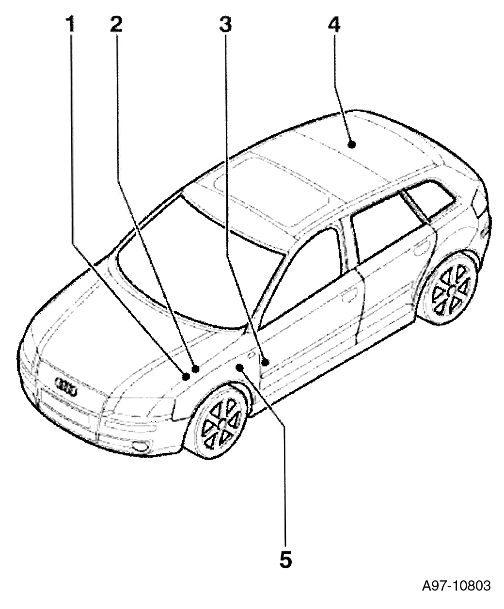
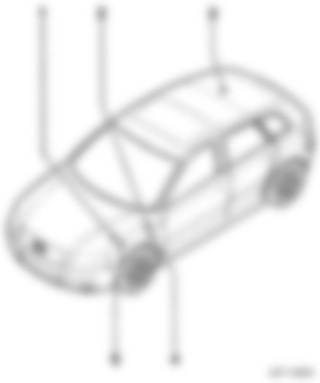
Fig. 1: Audi A3 2007 - Component Locations - Fuse Location Overview
Location No. Description Refer To Illustration 1 Fuse Panel A -SA- Fig. 2, Fig. 3, Fig. 4 2 Relay / Fuse Panel B -SB- Fig. 5, Fig. 6 3 Fuse Panel C -SC- Fig. 7 4 Fuse Panel D -SD- Fig. 8 5 Fuses Under Instrument Panel, Left Fig. 9

Fig. 4: Audi A3 2007 - Component Locations - Main Fuse Panel S -SA- Electronics Box High


Fig. 7: Audi A3 2007 - Component Locations - Fuse Panel C -SC- Instrument Panel - Left Side

Fig. 9: Audi A3 2007 - Component Locations - Relay/Fuse Panel Under Instrument Panel - Left Side

Audi A3 2007 - 1 - Fuse Panel A -SA-
For relay and fuse panel location and position, refer to appropriate information under 1.2- MAIN FUSE PANEL: A -SA- ON ELECTRONICS BOX LOW (FROM MODEL YEAR 2006).
- Location Main Fuse Panel, Electronics Box Low, from model year 2006.
- Position of Fuses Main Fuse Panel, Electronics Box Low, from model year 2006.
- Position of Fuses Main Fuse Panel, Electronics Box Low, from model year 2007.
- Location Main Fuse Panel, Electronics Box Low, from November 2008.
- Position of Fuses Main Fuse Panel, Electronics Box Low, from November 2008.
For relay and fuse panel location and position, refer to appropriate information under 1.7- MAIN FUSE PANEL A -SA- ON ELECTRONICS BOX HIGH.
- Location Main Fuse Panel, Electronics Box High.
- Position of Fuses Main Fuse Panel, Electronics Box High, from model year 2006.
Audi A3 2007 - 2 - Fuse Panel B -SB-
For relay and fuse panel location and position, refer to appropriate information under 1.12- FUSE PANEL B -SB- ON ELECTRONICS BOX LOW, ENGINE COMPARTMENT, LEFT SIDE.
- Location Electronics Box Low.
- Fuse Arrangements Electronics Box Low, from model year 2006.
- Fuse Arrangements Electronics Box Low, from model year 2007.
For relay and fuse panel location and position, refer to appropriate information under 1.15 - FUSE PANEL B -SB- ON ELECTRONICS BOX HIGH, ENGINE COMPARTMENT, LEFT SIDE.
- Location Electronics Box High.
- Position of Fuses Electronics Box High, from model year 2006.
- Position of Fuses Electronics Box High, from model year 2007.
Audi A3 2007 - 3 - Fuse Panel C -SC-
For relay and fuse panel location and position, refer to appropriate information under 1.19- FUSE PANEL C -SC- INSTRUMENT PANEL - LEFT SIDE.
- Location.
- Position of Fuses from model year 2006.
- Position of Fuses, from model year 2007.
Audi A3 2007 - 4 - Fuse Panel D -SD-
For relay and fuse panel location and position, refer to appropriate information under 1.23 - MAIN FUSE PANEL D -SD- IN LUGGAGE COMPARTMENT, RIGHT REAR.
- Location Main Fuse Panel.
- Position of Fuses Main Fuse Panel, from model year 2006.
Audi A3 2007 - 5 - Fuses Under Instrument Panel, Left
For relay and fuse panel location and position, refer to appropriate information under 1.26- FUSES UNDER INSTRUMENT PANEL, LEFT SIDE (FROM MODEL YEAR 2006).
- Component: -S37- , -S280- and -S131-.
- Position of Fuses, from model year 2006.
Audi A3 2007 - 1- RELAYS 1.1- Overview Of Relays
NOTE: For fuse identification within the relay and fuse holder panels, refer to 1.1- Overview Of Fuses under fuses.
Fig. 10: Audi A3 2007 - Component Locations - Relay Location Overview
Location No. Description Refer To Illustration 1 Relay Carrier on Electronics Box
(In engine compartment, left side)Fig. 11, Fig. 12 2 Relay Arrangements
(Under left instrument panel)Fig. 15 3 Position of Relays on Main Fuse Panel
(In luggage compartment, right rear side)Fig. 18 4 Relay Carrier on Vehicle Electrical System Control Module
(Under instrument panel, left side)Fig. 13, Fig. 14 5 Relay Carrier Under Electronics Box
(In engine compartment, left side)Fig. 16, Fig. 17
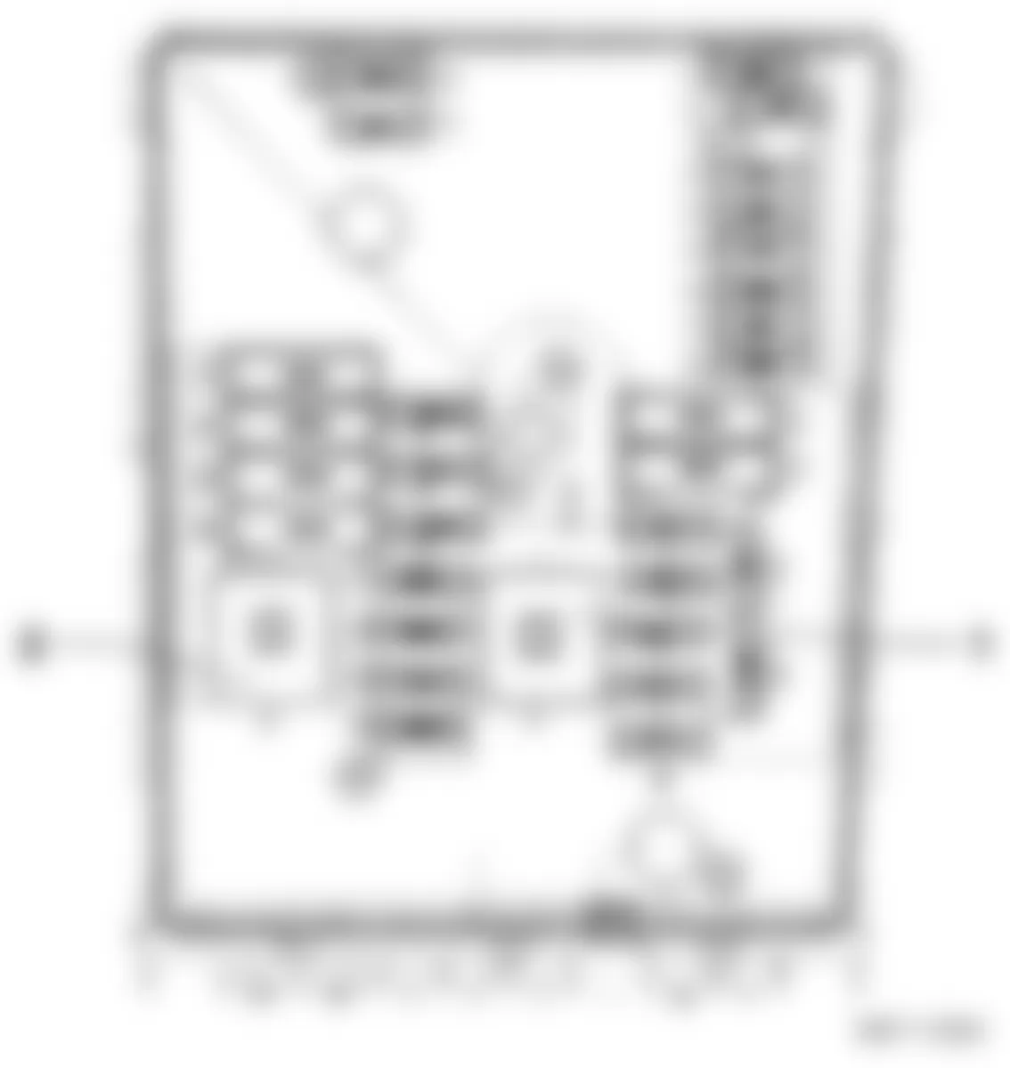


Fig. 15: Audi A3 2007 - Component Locations - Position Of Relays Under Instrument Panel Left Side
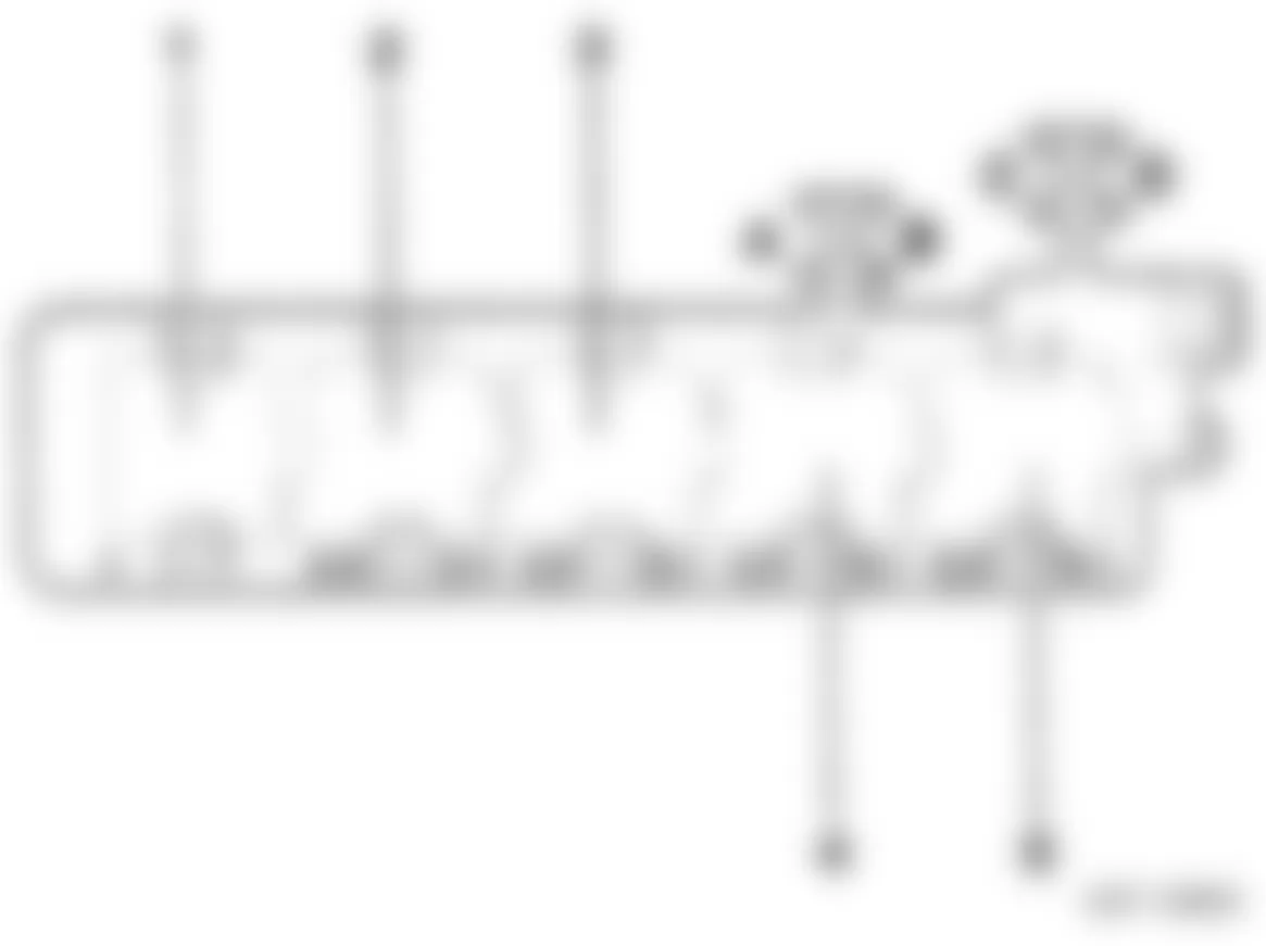
Fig. 16: Audi A3 2007 - Component Locations - Position Of Relays Under Electronics Box

Fig. 17: Audi A3 2007 - Component Locations - Relay Position Under Electronics Box


Audi A3 2007 - 1 - Relay Carrier On Electronics Box, In Engine Compartment, Left Side
- Component:-J271-, -J317-, -J363-, -J757-, -J329.
- Position of Relays Electronics Box Low, from model year 2006.
- - 1.2- POSITION OF RELAYS ON ELECTRONICS BOX LOW, FROM MODEL YEAR 2006.
- Position of Relays Electronics Box High, from model year 2006.
- - 1.4- POSITION OF RELAYS ON ELECTRONICS BOX HIGH, FROM MODEL YEAR 2006.
Audi A3 2007 - 2 - Relay Arrangements, Under Left Instrument Panel
- Component: -J17-,-J49-,-J359-, J906-, -J907-, -J910
- Position of Relays, from model year 2006.
- - 1.7- POSITION OF RELAYS UNDER INSTRUMENT PANEL, LEFT SIDE (FROM MODEL YEAR 2006).
- Position of Relays, from model year 2009.
- - 1.8- POSITION OF RELAYS UNDER INSTRUMENT PANEL, LEFT SIDE (FROM MODEL YEAR 2009).
Audi A3 2007 - 3 - Position Of Relays On Main Fuse Panel, In Luggage Compartment, Right Rear
- Component: -J655-, -N253-.
- Position of Relays, from model year 2006.
- - 1.11- POSITION OF RELAYS ON MAIN FUSE PANEL, IN LUGGAGE COMPARTMENT - RIGHT REAR.
Audi A3 2007 - 4 - Relay Carrier On Vehicle Electrical System Control Module, Under Instrument Panel, Left Side
- Component: -J681- , -J9- , -J413- , -J59- , -J729- , -J689- , -J730-.
- Position of Relays, from model year 2006.
- Position of Relays, from model year 2010.
Audi A3 2007 - 5 - Relay Carrier Under Electronics Box
- Component:-J179-, -J299-.
- Position of Relays, from model year 2006.
Audi A3 2007 - COMPONENT IDENTIFICATION FUSES - CIRCUIT PROTECTION
WARNING: Never replace a fuse with one that has a higher amperage rating. A fuse with a too high amperage could damage the electrical part and possible cause a fire.
For access to instrument panel fuse box, refer to illustration below.

The individual circuits are protected by fuses. The fuse panels with the fuses are located in the engine compartment, in the passenger compartment on the left front face of the instrument panel behind a cover and in the right storage area in the luggage compartment.
There is a plastic clip (fuse puller) in the cover on the left side of the instrument panel, which can be used to remove the fuses. The crank handle is used for emergency operation of the power roof (if equipped).
Two spare fuses and a sticker identifying the fuses are located on the inside of the fuse box cover.
Fuses with the proper ampere ratings are available at your Audi dealer.
NOTE:
AUTOMATIC CIRCUIT BREAKERS:
The electric seat adjusters are protected with circuit breakers which reset automatically after the circuit overload has been corrected.
Audi A3 2007 - Fuse - Color Codes
Identifying fuse color and ampere rating, refer to table below.
WARNING: Never replace a fuse with one that has a higher amperage rating. A fuse with a too high amperage could damage the electrical part and cause a fire.
Audi A3 2007 IDENTIFYING FUSE BY COLOR
Current Rating Amperes Color 1A Black 3A Violet 5A Light Brown 7.5A Brown 10A Red 15A Blue 20A Yellow 25A White or Natural 30A Green 35A Green-Blue 40A Orange 50A Red 60A Yellow 100A Blue
Audi A3 2007 - Replacing A Fuse
A problem in the electrical system may be caused by a blown fuse.
- Switch off the ignition and the electrical component affected.
- Carefully pry the face cover off the instrument panel using the ignition key or a screwdriver. See Fig. 19.
- Check the fuse index to find out which fuse belongs to the component which has failed. See FUSE INDEX INFORMATION.
- Remove the blown fuse with the plastic clip provided. The clip is located on the holder in the fuse box cover.
- Replace a blown fuse (recognizable by the melted metal strip inside) with a fuse of the same amperage.
- Firmly snap the cover back onto the instrument panel face.
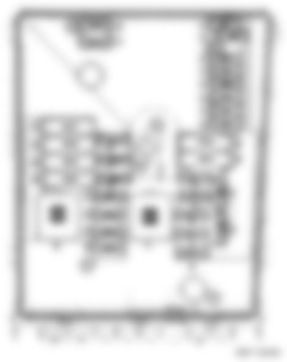
Audi A3 2007 - FUSE INDEX INFORMATION 1.2- MAIN FUSE PANEL: A -SA- ON ELECTRONICS BOX LOW (FROM MODEL YEAR 2006)
NOTE: The fuse panel A -SA- is located on the left side of the engine compartment, refer to illustration below.
For fuse identification and amperage rating refer to FUSE - COLOR CODES.

1.2.1 - MAIN SUPPLY CONNECTION:
M - Threaded connection M (terminal 30). See Fig. 20.
1.3 - FUSE ARRANGEMENTS ELECTRONICS BOX LOW, FROM MODEL YEAR 2006:
Audi A3 2007 IDENTIFYING FUSES (MAIN FUSE PANEL A -SA- ELECTRONIC BOX LOW - FROM MODEL YEAR 2006)
Location/
PositionRating (A) Function/Component Wiring
IDTerminal 1 150A Generator (GEN) -C- (70A)
Generator (GEN) -C- (90A)
Generator (GEN) -C- (110A)
Generator (GEN) -C- (120A)SA1 30 1 200A Generator (GEN) -C- (140A) SA1 30 2 80A Power Steering Control Module -J500- SA2 30 3 50A Coolant Fan Control (FC) Control Module -J293-
Coolant Fan Control (FC) Thermal Switch -F18-
Coolant Fan -V7-SA3 30 4 80A Fuses Supply:
-SC12- through -SC17- -SC19- -SC22- through -SC27- -SC28- -SC38- Not applicable from November 2005SA4 30 5 80A Fuses Supply:
-SC12- through -SC17- -SC19- -SC22- through -SC27- -SC28- -SC38- Not applicable from November 2005SA5 30 5 100A Auxiliary Air Heater Control Module -J604-
Not Applicable from November 2005SA5 30 6 100A Auxiliary Air Heater Control Module -J604-
Applicable from November 2005SA6 30 7 50A Doctor Option SA7 30 80A Police Option SA7 30
1.4 - FUSE ARRANGEMENTS ELECTRONICS BOX LOW, FROM MODEL YEAR 2007:
Audi A3 2007 IDENTIFYING FUSES (MAIN FUSE PANEL A -SA- ELECTRONIC BOX LOW - FROM MODEL YEAR 2007)
Location/
PositionRating (A) Function/Component Wiring
IDTerminal 1 150A Generator (GEN) -C- (70A)
Generator (GEN) -C- (90A)
Generator (GEN) -C- (110A)
Generator (GEN) -C- (120A)SA1 30 1 200A Generator (GEN) -C- (140A) SA1 30 2 80A Power Steering Control Module -J500- SA2 30 3 50A Coolant Fan Control (FC) Control Module -J293-
Coolant Fan Control (FC) Thermal Switch -F18-
Coolant Fan -V7-SA3 30 4 40A Preheating Coolant, Low Heat Output Relay -J359-
Applicable from November 2006SA4 30 5 80A B272 Plus Connection (30) (in main wiring harness)
Fuses Supply:
-SC12 through -SC 17-, -SC22- through -SC27-, -SC28-, -SC38-, -SC43-SA5 30 6 100A Auxiliary Air Heater Control Module -J604-
Not Applicable from November 2006SA6 30 6 80A Preheating Coolant, High Heat Output Relay -J360-
Applicable from November 2006SA6 30 7 50A Doctor Option SA7 30 7 80A Police Option SA7 30 7 30A Electronic Damping Control Module -J250- Applicable from May 2008 SA7 30
Audi A3 2007 - 1.5- MAIN FUSE PANEL: LOCATION FUSE PANEL A -SA- ON ELECTRONICS BOX LOW (FROM NOVEMBER 2008)
NOTE: The fuse panel A -SA- is located on the left side of the engine compartment, refer to illustration below.
For fuse identification and amperage rating refer to FUSE - COLOR CODES.
1.5.1 - MAIN SUPPLY CONNECTION:
M - Threaded connection M (terminal 30). See Fig. 21.
1.6 - FUSE ARRANGEMENTS ELECTRONICS BOX LOW, FROM MODES YEAR 2007:
Audi A3 2007 IDENTIFYING FUSES (MAIN FUSE PANEL A -SA- ELECTRONIC BOX LOW - FROM NOVEMBER 2008)
Location/
PositionRating (A) Function/Component Wiring
IDTerminal 1 150A Generator (GEN) -C- (70A)
Generator (GEN) -C- (90A)
Generator (GEN) -C- (110A)
Generator (GEN) -C- (120A)SA1 30 1 200A Generator (GEN) -C- (140A) SA1 30 2 80A Power Steering Control Module -J500- SA2 30 3 50A Coolant Fan Control (FC) Control Module -J293-
Coolant Fan Control (FC) Thermal Switch -F18-
Coolant Fan -V7-SA3 30 4 80A Preheating Coolant, High Heat Output Relay -J360- SA4 30 5 80A B272 Plus Connection (30) (in main wiring harness)
Fuses Supply:
-SC12 through -SC 17-, -SC22- through -SC27- -SC28- -SC38- -SC43-SA5 30 6 40A Preheating Coolant, High Heat Output Relay -J359- SA6 30 7 50A Doctor Option
Not Applicable from May 2009SA7 30 7 50A Doctor or Police Option
Applicable from May 2009SA7 30 7 80A Police Option
Not Applicable from May 2009SA7 30 7 30A Electronic Damping Control Module -J250- SA7 30
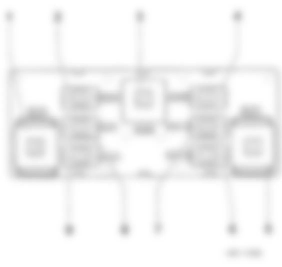
Audi A3 2007 - 1.7- MAIN FUSE PANEL A -SA- ON ELECTRONICS BOX HIGH
NOTE: The fuse panel A -SA- is located on the left side of the engine compartment, refer to illustration below.
Fig. 22: Audi A3 2007 - Component Locations - Main Fuse Panel A -SA- Electronic Box High

1.7.1 - MAIN SUPPLY CONNECTION:
- - Threaded connection A (terminal 30). See Fig. 22.
- - Threaded connection M (terminal 30).
- - Threaded connection L (terminal 30).
1.10 - ELECTRONICS BOX HIGH, ENGINE CODES AXX, BWA, BPY, BHZ, BZC, CDLA, CDLC, FROM MODEL YEAR 2006:
Audi A3 2007 IDENTIFYING FUSES (MAIN FUSE PANEL A -SA- ELECTRONIC BOX HIGH - FROM MODEL YEAR 2006)
Location/
PositionRating (A) Function/Component Wiring
IDTerminal 4 150A Generator (GEN) -C- (70A)
Generator (GEN) -C- (90A)
Generator (GEN) -C- (110A)
Generator (GEN) -C- (120A)SA1 30 4 200A Generator (GEN) -C- (140A) SA1 30 5 80A Power Steering Control Module -J500- SA2 30 6 50A Coolant Fan Control (FC) Control Module -J293- SA3 30 7 80A Fuses Supply:
-SC12- through -SC17-, -SC19-, -SC22- through -SC27-, -SC28-, -SC38- Not applicable from November 2005SA4 30 7 80A Fuses Supply:
-SC12- through -SC17-, -SC22- through -SC27-, -SC28-, -SC38-, -SC43- Applicable from May 2009SA4 30 8 80A Fuses Supply:
-SC12- through -SC17-, -SC19-, -SC22- through -SC27-, -SC28-, -SC38- Applicable from November 2005SA5 30 8 80A Fuses Supply:
-SCI2- through -SC17-, -SC22- through -SC27-, -SC28-, -SC38-, -SC43- Applicable from May 2006
Not applicable from May 2009SA5 30 9 - Not used SA6 - 10 50A Doctor Option
Not Applicable from May 2009SA7 30 10 50A Doctor or Police Option
Applicable from May 2009SA7 30 10 80A Police Option
Not Applicable from May 2009SA7 30 10 30A Electronic Damping Control Module -J250-
Applicable from May 2008SA7 30
1.11 - ELECTRONICS BOX HIGH, ENGINE CODES BMJ, BUB, CBRA, FROM MODEL YEAR 2006:
Audi A3 2007 IDENTIFYING FUSES (MAIN FUSE PANEL A -SA- ELECTRONIC BOX HIGH - FROM MODEL YEAR 2006)
Location/
PositionRating (A) Function/Component Wiring
IDTerminal 4 150A Generator (GEN) -C- (70A)
Generator (GEN) -C- (90A)
Generator (GEN) -C- (110A)
Generator (GEN) -C- (120A)SA1 30 4 200A Generator (GEN) -C- (140A) SA1 30 5 80A Power Steering Control Module -J500- SA2 30 6 50A Coolant Fan Control (FC) Control Module -J293- SA3 30 7 80A Fuses Supply:
-SC22- through -SC27-, -SC2S-, -SC38- Applicable from May 2009SA4 30 8 80A Fuses Supply:
-SC22- through -SC27-, -SC28-, -SC38- Not applicable from May 2009SA5 30 9 50A Fuses Supply:
-SC12- through -SC17-, -SC19-, -SC44-, -SC45- Not applicable from November 2005SA6 30 9 50A Fuses Supply:
-SC44-, -SC45- Applicable from November 2005SA6 30 10 50A Doctor Option
Not Applicable from May 2009SA7 30 10 50A Doctor or Police Option
Applicable from May 2009SA7 30 10 80A Police Option
Not Applicable from May 2009SA7 30 10 30A Electronic Damping Control Module -J250-
Applicable from May 2008SA7 30
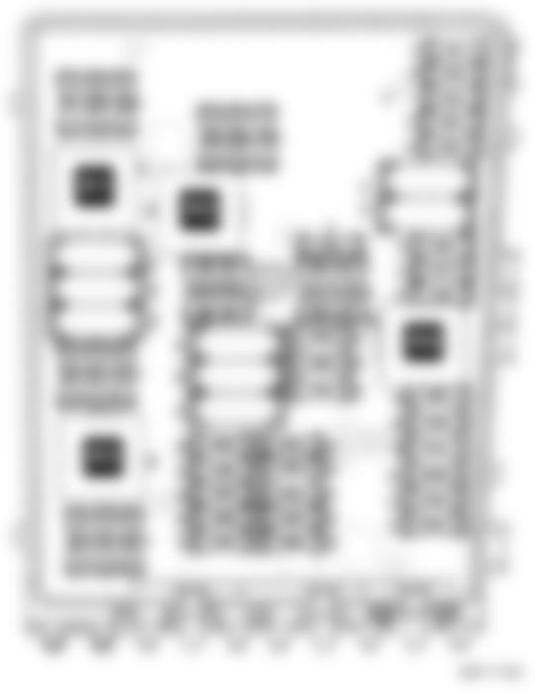
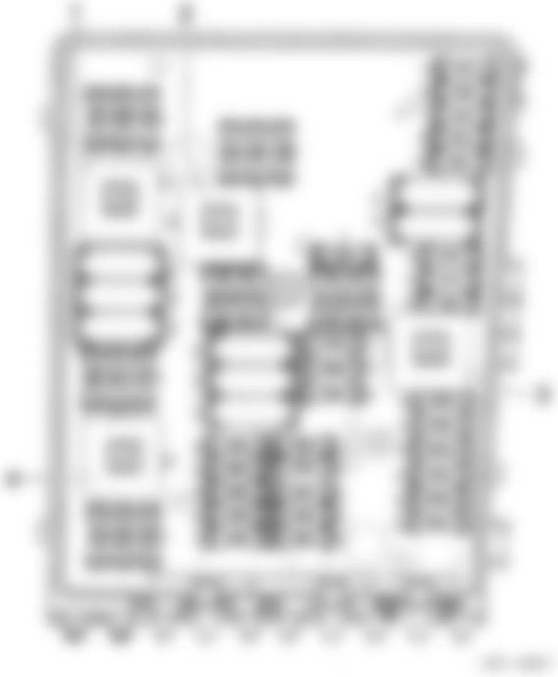
Audi A3 2007 - 1.12- FUSE PANEL B -SB- ON ELECTRONICS BOX LOW, ENGINE COMPARTMENT, LEFT SIDE
NOTE: The relay and fuse panel B -SB- is located in electronic box on left side of the engine compartment, refer to illustration below. For relay identification related to relay and fuse panel B -SB- refer to appropriate POSITION OF RELAYS ON ELECTRONICS BOX under RELAY INDEX INFORMATION.
1.12.1 - FUSE COLOR: For fuse identification and amperage rating refer to FUSE - COLOR CODES.
1.13 - FUSE ARRANGEMENTS ELECTRONICS BOX LOW, FROM MODEL YEAR 2006:
Audi A3 2007 IDENTIFYING FUSES (ELECTRONICS BOX LOW - FROM MODEL YEAR 2006)
Fuse
No.Rating
(Amperage)Function/Component Wiring
ID.Terminal F1 20A Comfort System Central Control Module -J393- SB1 30 F2 5A Steering Column Electronic Systems Control Module -J527- SB2 30 F3 5A Vehicle Electrical System Control Module -J519- SB3 30 F4 30A ABS Control Module -J104-
ABS Hydraulic Unit -N55-SB4 30 F5 15A Direct Shift Gearbox (DSG) Mechatronic -J743- SB5 30 F6 5A Instrument Cluster Control Module -J285- SB6 30 F7 - Not used - - F8 15A Radio -R-
Navigation System Operating Electronics Control Module -J402-SB8 30 F9 5A Navigation System Control Module with CD drive -J401-
Navigation System Tuner, TV -J415-
Satellite Radio -R146-
Telephone Transceiver -R36-
Amplifier for telephone -R86-SB9 30 F10 5A Motronic Engine Control Module (ECM) -J220-
Motronic Engine Control Module (ECM) Power Supply Relay -J271-
Power Supply Relay (terminal 30) -J317-SB10 30 F11 20A Auxiliary Heater Control Module -J364- SB11 30 F12 5A Data Bus On Board Diagnostic Interface -J533- SB12 30 F13 30A Engine Control Module (ECM) -J623-
Diesel Direct Fuel Injection (DFI) Engine Control Module (ECM) -J248-SB13 87 F13 25A Motronic Engine Control Module (ECM) -J220-
Engine Control Module (ECM) -J623-SB13 87 F14 20A Ignition Coil 1 with Power Output Stage -N-
Ignition Coil 2 -N128-
Ignition Coil 1 with Power Output Stage -N70-
Ignition Coil 2 with Power Output Stage -N127-
Ignition Coil 3 with Power Output Stage -N291-
Ignition Coil 4 with Power Output Stage -N292-SB14 87 F15 15A Oxygen Sensor (O2S) Heater 1 (behind Three Way Catalytic Converter (TWC) -Z29-
Oxygen Sensor (O2S) Heater 2 (behind Three Way Catalytic Converter (TWC) -Z30-
Oxygen Sensor (O2S) Heater 2 (behind Three Way Catalytic Converter (TWC) -Z64-SB15 87 F15 10A Oxygen Sensor (O2S) Heater 1 (behind Three Way Catalytic Converter (TWC) -Z29- SB15 87 F15 5A Automatic Glow Time Control Module -J179-
Fuel Pump (FP) Relay -J17-SB15 87 F16 30A ABS Control Module -J104-
ABS Hydraulic Pump -V64-SB16 30 F17 15A High Tone Horn -H2-
Low Tone Horn -H7-SB17 30 F18 30A Amplifier -R12-
Bass Speakers Amplifier, in luggage compartment, left -R44-SB18 30 F19 30A Wiper Motor Control Module -J400- SB19 30 F20 - - - - F21 15A Oxygen Sensor (O2S) Heater -Z19-
Oxygen Sensor (O2S) Heater 2 -Z28-
Oxygen Sensor (O2S) Heater 1 (behind Three Way Catalytic ConverterSB21 87 F21 10A Oxygen Sensor(O2S) Heater -Z19- SB21 87 F22 5A Brake Pedal Switch -F63-
Clutch Position Sensor -G476-SB22 87 F23 15A Fuel Pressure Regulator Valve -N276- SB23 87 F23 10A EGR Vacuum Regulator Solenoid Valve -N18-
Wastegate Bypass Regulator Valve -N75-
EGR Valve 2 -N213-
Exhaust Gas Recirculation (EGR) Cooler Switch-Over Valve -N345-SB23 87 F23 5A Secondary Air Injection (AIR) Pump Relay -J299- SB23 87 F24 10A Map Controlled Engine Cooling Thermostat -F265-
Evaporative Emission (EVAP) Canister Purge Regulator Valve 1 -N80-
Intake Manifold Tuning (IMT) Valve -N156-
Camshaft Adjustment Valve 1 -N205-
Intake Flap Motor -V157-SB24 87 F25 40A Vehicle Electrical System Control Module -J519-
(Right Parking Lamp, Right High Beam Lamp, Right Low Beam Lamp, Right Parking Lamp, Right Front Fog Lamp)SB25 30 F26 40A Vehicle Electrical System Control Module -J519-
(Left Parking Lamp, Left High Beam Lamp, Left Low Beam Lamp, Left Parking Lamp, Left Front Fog Lamp)SB26 30 F27 50A Automatic Glow Time Control Module -J179-
Glow Plug 1 -Q10-
Glow Plug 2 -Q11-
Glow Plug 3 -Q12-
Glow Plug 4 -Q13-SB27 87 F27 40A Secondary Air Injection (AIR) Pump Motor -V101- SB27 87 F28 40A Power Supply Relay 2 (terminal 15) -J681-
Fuses Supply:
-SC1- through -SC6-, -SC7- through -SC11-, -SC29- through -SC31-, - SC39-, -SC47-, -SC49-SB28 30 F29 50A Fuses Supply:
-SC18-, -SC20-, -SC32-through-SC37-, -SC44-, -SC45-, -SC48-, -S131-SB29 30 F30 50A (1) Load Reduction Relay -J59-
Fuses Supply:
-SC40-, -SC41-, -SC42-, -SC46-SB30 30
(1) Fuse was increased from 40A to 50A, applicable from November 2005.
1.14 - FUSE ARRANGEMENTS ELECTRONICS BOX LOW, FROM MODEL YEAR 2007:
Audi A3 2007 IDENTIFYING FUSES (ELECTRONICS BOX LOW - FROM MODEL YEAR 2007)
Fuse
No.Rating
(Amps)Function/Component Wiring
ID.Terminal F1 40A Voltage Stabilizer -J532-
Fuses Supply:
-SC7- through -SC11-
(Only models with stop/start system, Applicable from model year 2010)SB1 30 F1 40A Fuses Supply:
(Only models without stop/start system, Applicable from model year 2010)SB1 30 F2 5A Steering Column Electronic Systems Control Module -J527-
(Not applicable from model year 2009)SB2 30 F2 30A Direct Shift Gearbox (DSG) Mechatronic -J743-
(7-Speed Direct Shift Gearbox OAM)
Applicable from model year 2009SB2 30 F2 20A Fuel Pressure Regulator Valve -N276- (CBFA)
(From model year 2009)SB2 30 F3 5A Vehicle Electrical System Control Module -J519- SB3 30 F3 5A Battery Monitoring Control Module -J367-
(Applicable from model year 2010)SB3 30 F4 30A ABS Control Module -J104- (MK60 ESP-Valves)
ABS Control Module -J104- (MK70 ABS-Valves)
(Not applicable from model year 2009)SB4 30 F4 20A ABS Control Module -J104- (MK60 ESP-Valves)
(Applicable from model year 2009)SB4 30 F5 15A Direct Shift Gearbox (DSG) Mechatronic -J743- SB5 30 F6 5A Instrument Cluster Control Module -J285-
(Not applicable from model year 2010)SB6 30 F6 5A Steering Column Electronic Systems Control Module -J527-
(Applicable from model year 2009)SB6 30 F7 20A Fuel Pressure Regulator Valve -N276- (CBFA)
(Not applicable from model year 2009)SB7 30 F8 15A Navigation System Operating Electronics Control Module -J402-
Radio/Navigation Display Control Module -J503-
Radio -R-
(Not applicable from model year 2010)SB8 30 F8 25A Radio/Navigation Display Control Module -J503- (1)
Only with radio/navigation system Japan
(Not applicable from model year 2010)SB8 30 F9 5A Navigation System Control Module with CD drive -J401- (1)
Navigation System Tuner, TV -J415 (1)
Satellite Radio -R146-
Telephone Transceiver -R36-
Amplifier for telephone -R86- (1)
18-Pin Connector -T18a- (VDA-Interface) (1)
(Not applicable from model year 2010)SB9 30 F10 5A Power Supply Relay (terminal 30) -J317-
(BKC, BXE, AZV, BKD, BLS, BMM, BUY, BMN, CBBB, CBAB, CBAA, CAYB, CAYC, CBFA)SB10 30 F10 5A Engine Control Modules (ECM) -J-
(CAXC, CBBB, CBAB, CBAA, CAYB, CAYC, CBFA)
Motronic Engine Control Module (ECM) Power Supply Relay -J271-
(CAXC)SB10 30 F10 10A Engine Control Modules (ECM) -J...-
(BLF, BPT, BPU, BVZ, BVY, BZB, CAWB, CBFA, CCTA, CDAA, CCZA)
Motronic Engine Control Module (ECM) Power Supply Relay -J271-
(BLF, BPT, BPU, BVZ, BVY, BZB, CAWB, CBFA, CCTA, CDAA, CCZA)SB10 30 F11 20A Auxiliary Heater Control Module -J364- (1) SB11 30 F12 5A Data Bus On Board Diagnostic Interface -J533- SB12 30 F13 30A Engine Control Modules (ECM) -J-
(BKC, BXE, AZV, BKD, BLS, BMM, BUY, BMN, CBBB, CBAB, CBAA, CAYB, CAYC, CBFA)SB13 87 F13 25A Engine Control Modules (ECM) -J...- (BLF, BPT, BPU, B BVZ, BVY, BSE, BSF) Not applicable from May 2007, only models with engine codes BSE, BSF SB13 87 F13 15A Engine Control Modules (ECM) -J...- (CAXC, BZB, CAWB, CBFA, CCTA, CDAA, CCZA) Applicable from May 2007. only models with engine codes BSE, BSF, CCSA SB13 87 F14 20A Ignition Coil 1 with Power Output Stage -N- (BSE, BSF, CCSA)
Ignition Coil 2 -N128- (BSE, BSF, CCSA)SB14 87 F14 20A Ignition Coil 1 with Power Output Stage -N70-
Ignition Coil 2 with Power Output Stage -N127-
Ignition Coil 3 with Power Output Stage -N291-
Ignition Coil 4 with Power Output Stage -N292-
(Only models with engine codes BLF, BPT, BPU, BYT, BVZ, BVY, CAXC, BZB, CAWB, CBFA, CCTA, CD CCZA)SB14 87 F14 20A Fuel Pressure Regulator Valve -N276- (CBBB, CBAB, CBAA, CAYB, CAYC, CBFA)
Fuel Metering Valve -N290- (CBBB, CBAB, CBAA, CAYB, CAYC, CBFA)SB14 87 F15 15A Oxygen Sensor (O2S) Heater 1 (behind Three Way Catalytic Converter (TWC) -Z29- (BVY)
Oxygen Sensor (O2S) Heater 2 (behind Three Way Catalytic Converter (TWC) -Z30- (BVY)
Oxygen Sensor (O2S) Heater 2 (behind Three Way Catalytic Converter (TWC) -Z64- (BVY)SB15 87 F15 10A Oxygen Sensor (O2S) Heater 1 (behind Three Way Catalytic Converter (TWC) -Z29- (BVZ) SB15 87 F15 10A Oxygen Sensor (O2S) Heater 1 (behind Three Way Catalytic Converter (TWC) -Z29- (CAXC)
Oxygen Sensor (O2S) Heater 1 -Z19- (CAXC)SB15 87 F15 5A Camshaft Adjustment Valve 1 -N205- (BPT, BPU, BYT) SB15 87 F15 5A Radiator Identification Sensor -G611- (CBFA)
Leak Detection Pump (LDP) -V144- (CBFA, CCTA)
Oxygen Sensor (O2S) Heater 1 -Z19- (CBFA)SB15 87 F15 5A Fuel Pump (FP) Relay -J17-
Automatic Glow Time Control Module -J179-
Only models with engine codes BKC, BXE, AZV, BKD, BLS, BMM, BUY, BMN, CBBB, CBAB, CBAA, CAYB, CAYC, CBEASB15 87 F15 5A Preheating Coolant, Low Heat Output Relay -J359-
Preheating Coolant High Heat Output Relay -J360-
Only models with engine codes BKC, BXE, AZV, BKD, BLS, BMM, BUY, BMN, CBBB, CBAB, CBAA, CAYB, CAYC, CBEA
Applicable from November 2006, only models with auxiliary air heaterSB15 87 F15 5A Auxiliary Fuel Pump Relay -J832-
(CBBB, CBAB, CBAA, CBEA)SB15 87 F16 30A ABS Control Module -J104- (ABS Pump)
Not applicable from model year 2009SB16 30 F16 30A Vehicle Electrical System Control Module -J519-
Right Parking Lamp, Right High Beam Lamp, Right Low Beam Lamp, Right Parking Lamp, Right Front Fog Lamp Supply
Applicable from model year 2009SB16 30 F17 15A High Tone Horn -H2-
Low Tone Horn -H7-SB17 30 F18 30A Amplifier -R12-
Bass Speakers Amplifier, in luggage compartment, left -R44-SB18 30 F18 30A Voltage Stabilizer -J532-
Amplifier -R12-
Bass Speakers Amplifier, in luggage compartment, left -R44-
Only models with stop/start system
Applicable from model year 2010SB18 30 F19 30A Wiper Motor Control Module -J400- SB19 30 F20 20A Fuel Pressure Regulator Valve -N276-
(BYT, BPT, BPU, BZB, CAWB, CCTA, CDAA, CCZA)SB20 87 F20 10A Coolant Pump -V50- (CAXC) SB20 87 F21 10A Oxygen Sensor (O2S) Heater 2 (behind Three Way Catalytic Converter (TWC) -Z64- (CBFA) SB21 87 F21 10A Oxygen Sensor (O2S) Heater -Z19- (BSE, BSF, BLF, BPT, BPU, BYT, BVZ, BVY, BLS, BMM, BUY, BMN, BZB, CAWB, CCTA, CCSA, CDAA, CCZA, CBBB, CBAB, CBAA, CAYB, CAYC, CBEA)
Oxygen Sensor (O2S) Heater 1 (behind Three Way Catalytic Converter (TWC) -Z29- (BSE, BSF, BLF, CCTA, CBFA, CCSA, CD CCZA, CBEA)
Not applicable from May 2009, only models with engine codes BSE, CCSA, CCTA, CCZA, CDAASB21 87 F21 15A Oxygen Sensor (O2S) Heater -Z19- (BSE, CCSA, CCTA, CCZA, CDAA)
Oxygen Sensor (O2S) Heater 1 (behind Three Way Catalytic Converter (TWC) -Z29- (BSE, CCSA, CCTA, CCZA, CDAA)
Applicable from model year 2010SB21 87 F21 20A Vacuum Pump Relay -J57- (CAXC)
Brake System Vacuum Pump -V192- (CAXC)SB21 87 F22 5A Clutch Position Sensor -G476- SB22 87 F22 5A Brake Light Switch -F-
Brake Pedal Switch -F63-
Applicable from model year 2010SB22 87 F23 5A Coolant Circulation Pump Relay -J151- (BPT, BPU, BYT, BZB, CAWB, CCTA, CBFA, CCZA, CDAA)
Secondary Air Injection (AIR) Pump Relay -J299- (BSE, CBFA, CCSA)
After-Run Coolant Pump -V51- (BPT, BPU, BYT, BZB, CAWB, CCTA)SB23 87 F23 10A EGR Vacuum Regulator Solenoid Valve -N18- (BKC, BXE, AZV, BKD)
Wastegate Bypass Regulator Valve -N75- (BLS, BMM, BKC, BXE, AZV, BKD, BMN, BUY, CBBB, CBAB, CBAA, CAYB, CAYC, CBEA)
EGR Valve 2 -N213- (BKC, BXE, AZV, BKD)
Intake Manifold Runner Control (IMRC) Valve -N316- (BMN, BUY)
Exhaust Gas Recirculation (EGR) Cooler Switch-Over Valve -N345- (BLS, BMM)
Exhaust Gas Recirculation (EGR) Cooler Switch-Over Valve -N345- (BMN, BUY, CBBB, CBAB, CBAA, CAYB, CAYC)SB23 87 F23 10A Mass Air Flow (MAF) Sensor -G70- (CBBB, CBAB, CBAA)
Only models with stop/start system
Applicable from model year 2010SB23 87 F23 15A Fuel Pressure Regulator Valve -N276-
(BLF, CAXC, BVY, BVZ)SB23 87 F24 10A Coolant Fan Control (FC) Control Module -J293-
Engine Component Power Supply Relay -J757- (BPT, BPU, BYT, CAXC, CD CAWB, CCZA, CCTA)
Control Valve Control Module -J808- (CBEA)
Wastegate Bypass Regulator Valve -N75- (BPT, BPU, BYT, CAXC, CAWB, BZB, CCTA, CBFA, CDAA, CCZA)
Evaporative Emission (EVAP) Canister Purge Regulator Valve 1 -N80- (BPT, BPU, BYT, BSE, BSF, BLF, BVY, BVZ, CAXC, CAWB, BZB, CCTA, CBFA, CCSA, CDAA, CCZA)
Secondary Air Injection (AIR) Solenoid Valve -N112- (CBFA)
Intake Manifold Tuning (IMT) Valve -N 156- (BSE, BSF, BLF, BVY, BVZ, CCSA)
Camshaft Adjustment Valve 1 -N205- (BLF, BVY, BVZ, C CAWB, BZB, CCTA, CBFA, CDAA, CCZA)
Turbocharger Recirculating Valve -N249- (BPT, BPU, BYT, CAXC, CAWB BZB CCTA CBFA CDAA CCZA)
Intake Manifold Runner Control (IMRC) Valve -N316- (BPT, BPU, BYT, CAWB, BZB, CCTA, CBFA, CDAA, CCZA)
Oil Pressure Regulation Valve -N428-
Intake Flap Motor -V157- (BKC, BXE, AZV, BKD)
Exhaust Gas Recirculation (EGR) Cooler Pump -V400- (CBBB, CBAB, CBAA, CAYB, CAYC)
Electrohydraulic Engine Mounting Regulator Valve -N398- (CAYB, CAYC)SB24 87 F25 30A Vehicle Electrical System Control Module -J519-
(Right Parking Lamp, Right High Beam Lamp, Right Low Beam Lamp, Right Parking Lamp, Right Front Fog Lamp)
Not applicable from model year 2009SB25 30 F25 40A ABS Control Module -J104- (MK60 ESP-Pump)
ABS Control Module -J104- (MK70 ABS Pump -Valves)
Applicable from model year 2009SB25 30 F26 30A Vehicle Electrical System Control Module -J519-
(Left Parking Lamp, Left High Beam Lamp, Left Low Beam Lamp, Left Parking Lamp, Left Front Fog Lamp)SB26 30 F27 50A Automatic Glow Time Control Module -J179-
Glow Plug 1 -Q10-
Glow Plug 2 -Q11-
Glow Plug 3 -Q12-
Glow Plug 4 -Q13-
Only models with engine codes: BKC, BXE, AZV, BKD, BLS, BMM, BMN, BUY, CBBB, CBAB, CBAA, CAYB, CAYC, CBEASB27 30 F27 40A Secondary Air Injection (AIR) Pump Motor -V101-
(BSE, CBFA, CCSA)SB27 87 F28 40A Power Supply Relay 2 (terminal 15) -J681-
Fuses Supply:
-SC1- through -SC6-, -SC29- through -SC31-, -SC46-, -SC47-, -SC49-
Not applicable from model year 2009SB28 30 F29 50A B300 Plus Connection 4 (30) (in main wiring harness)
Fuses Supply:
-SC32- through -SC37-, -SC44-, -SC45-, -SC48-, -S30-
Not applicable from model year 2009SB29 30 F29 50A B300 Plus Connection 4 (30) (in main wiring harness)
Fuses Supply:
-SC32- through -SC37-, -SC39-, -SC44-, -SC45-, -SC48-, -S131-
Applicable from model year 2009SB29 30 F30 50A Load Reduction Relay -J59-
Fuses Supply:
-SC40-, -SC41-, -SC42-
Not applicable from model year 2009SB30 30 F30 50A Power Supply Relay 2 (terminal 15) -J681-
Fuses Supply:
-SC1- through -SC6-, -SC19-, -SC20-, -SC29- through -SC31-, -SC40-, -SC41-, -SC42-, -SC46-, -SC47-, -SC49-
Not applicable from model year 2009SB30 30
(1) Not for models U.S. equipment.
Audi A3 2007 - 1.15 - FUSE PANEL B -SB- ON ELECTRONICS BOX HIGH, ENGINE COMPARTMENT, LEFT SIDE
NOTE: The relay and fuse panel B -SB- is located in electronic box on left side of the engine compartment, refer to illustration below. For relay identification related to relay and fuse panel B -SB- refer to appropriate POSITION OF RELAYS ON ELECTRONICS BOX under RELAY INDEX INFORMATION.
1.15.1 - FUSE COLOR: For fuse identification and amperage rating refer to FUSE - COLOR CODES.
1.17 - FUSE ARRANGEMENTS ELECTRONICS BOX HIGH, FROM MODEL YEAR 2006:
Audi A3 2007 IDENTIFYING FUSES (ELECTRONICS BOX HIGH - FROM MODEL YEAR 2006)
Fuse
No.Rating
(Amperage)Function/Component Wiring
ID.Terminal F1 30A ABS Control Module -J104-
ABS Hydraulic Pump -V64-SB4 30 F2 30A ABS Control Module -J104-
ABS Hydraulic Unit -N55-SB4 30 F3 20A Comfort System Central Control Module -J393- SB1 30 F4 5A Vehicle Electrical System Control Module -J519- SB3 30 F5 15A High Tone Horn -H2-
Low Tone Horn -H7-SB17 30 F6 15A Fuel Pressure Regulator Valve -N276-
Transfer Fuel Pump (FP) -G6-SB23 87 F7 - Not used - - F8 - Not used - - F9 10A Wastegate Bypass Regulator Valve -N75-
Evaporative Emission (EVAP) Canister Purge Regulator Valve 1 -N80-
Turbocharger Recirculating Valve -N249-SB9 87 F10 10A Mass Air Flow (MAF) Sensor -G70-
Leak Detection Pump (LDP) -V144-SB10 87 F11 10A Oxygen Sensor (O2S) Heater -Z19-
Oxygen Sensor (O2S) Heater 2 -Z28-SB11 87 F12 10A Oxygen Sensor (O2S) Heater 1 (behind Three Way Catalytic Converter (TWC) -Z29-
Oxygen Sensor (O2S) Heater 2 (behind Three Way Catalytic Converter (TWC) -Z30-SB12 87 F13 15A Direct Shift Gearbox (DSG) Mechatronic -J743- SB13 30 F14 - Not used - - F15 10A After-run Coolant Pump -V51- SB15 87 F16 5A Steering Column Electronic Systems Control Module -J527- SB16 30 F17 5A Instrument Cluster Control Module -J285- SB17 30 F18 30A Amplifier -R12-
Bass Speakers Amplifier, in luggage compartment, left -R44-SB18 30 F19 15A Radio -R-
Navigation System Operating Electronics Control Module -J402-SB19 30 F20 5A Navigation System Control Module with CD drive -J401- (1)
Navigation System Tuner, TV -J415-(1)
Satellite Radio -R146-
Telephone Transceiver -R36-
Amplifier for telephone -R86- (1)SB20 30 F21 - Not used - - F22 - Not used - - F23 5A Motronic Engine Control Module (ECM) -J220-
Motronic Engine Control Module (ECM) Power Supply Relay -J271-SB23 30 F24 5A Data Bus On Board Diagnostic Interface -J533- SB24 30 F25 - Not used - - F26 - Not used - - F27 - Not used - - F28 25A Motronic Engine Control Module (ECM) -J220- SB28 87 F29 5A Coolant Circulation Pump Relay -J151-
Secondary Air Injection (AIR) Pump Relay -J299-SB29 87 F30 20A Auxiliary Heater Control Module -J364- SB30 30 F31 30A Wiper Motor Control Module -J400- SB31 30 F32 - Not used - - F33 - Not used - - F34 - Not used - - F35 - Not used - - F36 - Not used - - F37 - Not used - - F38 10A Evaporative Emission (EVAP) Canister Purge Regulator Valve 1 -N80- (1)
Intake Manifold Tuning (IMT) Valve -N156- (1)
Camshaft Adjustment Valve 1 -N205-
Camshaft Adjustment Valve 1 (exhaust) -N318- (1)
Coolant Fan Control (FC) Control Module -J293-SB38 87 F39 5A Brake Pedal Switch -F63-
Clutch Position Sensor -G476-SB39 87 F40 20A Ignition Coil 1 with Power Output Stage -N70-
Ignition Coil 2 with Power Output Stage -N127-
Ignition Coil 3 with Power Output Stage -N291-
Ignition Coil 4 with Power Output Stage -N292-SB40 87 F41 - Not used - - F42 5A Engine Component Power Supply Relay -J757- SB42 87 F43 30A Ignition Coil 1 with Power Output Stage -N70-
Ignition Coil 2 with Power Output Stage -N127-
Ignition Coil 3 with Power Output Stage -N291-
Ignition Coil 4 with Power Output Stage -N292-
Ignition Coil 4 with Power Output Stage -N323-
Ignition Coil 4 with Power Output Stage -N324-SB43 87 F44 - Not used - - F45 - Not used - - F46 - Not used - - F47 40A Vehicle Electrical System Control Module -J519-
(Left Parking Lamp, Left High Beam Lamp, Left Low Beam Lamp, Left Parking Lamp, Left Front Fog Lamp)SB47 30 F48 40A Vehicle Electrical System Control Module -J519-
Right Parking Lamp, Right High Beam Lamp, Right Low Beam Lamp, Right Parking Lamp, Right Front Fog Lamp SupplySB48 30 F49 40A Power Supply Relay 2 (terminal 15) -J681-
Fuses Supply:
-SC1- through -SC6-, -SC7- through -SC11-, -SC29- through -SC31-, -SC47-, -SC49-SB49 30 F50 - Not used SB50 30 F51 40A Secondary Air Injection (AIR) Pump Relay -J299-
Secondary Air Injection (AIR) Pump Motor -V101-SB51 30 F52 50A (2) Load Reduction Relay -J59-
Fuses Supply:
-SC40-, -SC41-, -SC42-, -SC46-SB52 30 F53 50A Fuses Supply:
-SC18-, -SC20-, -SC32-through-SC37-, -SC44-, -SC45-, -SC48-, -S131-SB53 30
(1) Not for models with US equipment.
(2) Fuse was increased from 40A to 50A, applicable from November 2005.
1.18 - FUSE ARRANGEMENTS ELECTRONICS BOX HIGH, FROM MODEL YEAR 2007:
Audi A3 2007 IDENTIFYING FUSES (ELECTRONICS BOX HIGH - FROM MODEL YEAR 2007)
Fuse
No.Rating
(Amps)Function/Component Wiring
ID.Terminal F1 30A ABS Control Module -J104- (ABS Pump)
Not applicable from model year 2009SB1 30 F1 30A Vehicle Electrical System Control Module -J519-
Right Parking Lamp, Right High Beam Lamp, Right Low Beam Lamp, Right Parking Lamp, Right Front Fog Lamp Supply,
Applicable from model year 2009SB1 30 F2 30A ABS Control Module -J104- (MK60 ESP-Valves)
ABS Control Module -J104- (MK70 ABS-Valves)
Not applicable from model year 2009SB2 30 F2 20A ABS Control Module -J104- (MK60 ESP-Valves)
Applicable from model year 2009SB2 30 F3 40A Voltage Stabilizer -J532-
Fuses Supply:
-SC7- through -SC11-
(Only models with stop/start system)
Applicable from model year 2010SB3 30 F3 40A Fuses Supply:
-SC7- through -SC10-
(Only models without stop/start system)
Applicable from model year 2010SB3 30 F4 5A Vehicle Electrical System Control Module -J519- SB4 30 F5 15A High Tone Horn -H2-
Low Tone Horn -H7-SB5 30 F6 15A Fuel Pressure Regulator Valve -N276-
(BPY, BWA, BHZ, BZC)SB6 87 F6 15A Transfer Fuel Pump (FP) -G6-
-Cylinder No. 1 Fuel Injector -N30
-Cylinder No. 2 Fuel Injector -N31
-Cylinder No. 3 Fuel Injector -N32
-Cylinder No. 4 Fuel Injector -N33
-Cylinder No. 5 Fuel Injector -N83
-Cylinder No. 6 Fuel Injector -N84
Only models with engine code BUD
Not applicable from model year 2009SB6 87 F7 15A Transfer Fuel Pump (FP) -G6-
-Cylinder No. 1 Fuel Injector -N30
-Cylinder No. 2 Fuel Injector -N31
-Cylinder No. 3 Fuel Injector -N32
-Cylinder No. 4 Fuel Injector -N33
-Cylinder No. 5 Fuel Injector -N83
-Cylinder No. 6 Fuel Injector -N84
Only models with engine code BUD, CBRA,
Applicable from model year 2009SB7 87 F7 15A Fuel Pressure Regulator Valve -N276- (CDLA, CDLC, BPY)
Applicable from model year 2009SB7 87 F8 - Not used - - F9 10A Wastegate Bypass Regulator Valve -N75-
Evaporative Emission (EVAP) Canister Purge Regulator Valve 1 -N80-
Turbocharger Recirculating Valve -N249-
Only models with eng. codes: BYP, BWA, BHZ, BZC, CDLA, CDLC, BZCSB9 87 F10 10A Leak Detection Pump -V144-
(BYP, BWA, BHZ, BZC, CDLA, CDLC, BZC)SB10 87 F10 10A Mass Air Flow (MAF) Sensor -G70- (BUD, CBRA) SB10 87 F11 10A Oxygen Sensor (O2S) Heater -Z19-
(BYP, BWA, BHZ, BZC, CDLA, CDLC, BZC)SB11 87 F11 10A Oxygen Sensor (O2S) Heater -Z19- (BUD, CBRA)
Oxygen Sensor (O2S) Heater 2 -Z28- (BUD, CBRA)SB11 87 F12 10A Oxygen Sensor (O2S) Heater 1 (behind Three Way Catalytic Converter (TWC) -Z29- (BYP, BWA, BHZ, BZC, CDLA, CDLC, BZC) SB12 87 F12 10A Oxygen Sensor (O2S) Heater 1 (behind Three Way Catalytic Converter (TWC) -Z29- (BUD, CBRA)
Oxygen Sensor (O2S) Heater 2 (behind Three Way Catalytic Converter (TWC) -Z30- (BUD, CBRA)SB12 87 F13 15A Direct Shift Gearbox (DSG) Mechatronic -J743- SB13 30 F14 - Not used - - F15 10A After-run Coolant pump -V51- SB15 87 F16 5A Steering Column Electronic Systems Control Module -J527-
(Not applicable from model year 2009)SB16 30 F17 5A Instrument Cluster Control Module -J285-
(Not applicable from model year 2010)SB17 30 F17 5A Steering Column Electronic Systems Control Module -J527-
(Applicable from model year 2009)SB17 30 F18 30A Amplifier -R12-
Bass Speakers Amplifier, in luggage compartment, left -R44-SB18 30 F18 30A Voltage Stabilizer -J532-
Amplifier -R12-
Bass Speakers Amplifier, in luggage compartment, left -R44-
Only models with stop/start system
Applicable from model year 2010SB18 30 F19 25A Radio/Navigation Display Control Module -J503-
Only with radio/navigation system Japan
(Not applicable from model year 2010)SB19 30 F19 15A Navigation System Operating Electronics Control Module -J402-
Radio/Navigation Display Control Module -J503-
Radio -R-
(Not applicable from model year 2010)SB19 30 F20 5A Navigation System Control Module with CD drive -J401-
Navigation System Tuner, TV -J415-
Telephone Transceiver -R36-
Amplifier for telephone -R86-
(Not applicable from model year 2010)SB20 30 F20 5A 18-Pin Connector -T18a- (VDA-Interface)
(Not for models with US equipment)
(Not applicable from model year 2010)SB20 30 F20 5A Satellite Radio -R146-
(Only models with US equipment)
(Not applicable from model year 2010)SB20 30 F20 5A Telephone Transceiver -R36-
(Not applicable from model year 2010)SB20 30 F21 - Not used - - F22 - Not used - - F23 10A Engine Control Modules (ECM) -J...-
Motronic Engine Control Module (ECM) Power Supply Relay -J271-SB23 30 F24 5A Data Bus On Board Diagnostic Interface -J533- SB24 30 F25 - Not used - - F26 - Not used - - F27 5A Exhaust Flap Valve -N220- (BHZ, CDLA, CDLC, BZC) SB27 87 F28 25A Engine Control Modules (ECM) -J... (BHZ, BUB, BWA, BPY, CDLA, BZC).
Not applicable from May 2007, only models with engine codes: BUB, BHZ, BWA, BPY, CDLA, CDLC.SB28 87 F28 15A Engine Control Modules (ECM) -J...
Applicable from May 2007, only models with engine codes: BUB, BHZ, BWA, BPY, CDLA, CDLC, CBRA, BZC.SB28 87 F29 5A Coolant Circulation Pump Relay -J151- (BUB, BWA, BPY, CDLA, CDLC, CBRA)
Secondary Air Injection (AIR) Pump Relay -J299- (BUB, CBRA)SB29 87 F30 20A Auxiliary Heater Control Module -J364- SB30 30 F31 30A Wiper Motor Control Module -J400- SB31 30 F32 - Not used - - F33 - Not used - - F34 - Not used - - F35 - Not used - - F36 - Not used - - F37 - Not used - - F38 10A Coolant Fan Control (FC) Control Module -J293- (BPY, BWA, BHZ, BUB, CDLA, CDLC, CBRA, BZC).
Evaporative Emission (EVAP) Canister Purge Regulator Valve 1 -N80- (BUB, CBRA).
Secondary Air Injection (AIR) Solenoid Valve -N112- (BUB, CBRA).
Intake Manifold Tuning (IMT) Valve -N156- (BUB, CBRA).
Camshaft Adjustment Valve 1 -N205- (BPY, BWA, BHZ, BUB, CDLA, CDLC, CBRA, BZC).
Secondary Air Injection (AIR) Solenoid Valve 2 -N320- (BUB, CBRA).
Leak Detection Pump (LOP) -V144- (BUB, CBRA).SB38 87 F39 5A Cutch Position Sensor -G476- SB39 87 F39 5A Brake Light Switch -F-
Brake Pedal Switch -F63-
Applicable from model year 2010SB39 87 F40 20A Ignition Coil 1 with Power Output Stage -N70-
Ignition Coil 2 with Power Output Stage -N127-
Ignition Coil 3 with Power Output Stage -N291-
Ignition Coil 4 with Power Output Stage -N292-
(Only models with engine codes: BPY, BWA, BHZ, CDLA, CDLC, BZC)SB40 87 F41 - Not used - - F42 5A Engine Component Power Supply Relay -J757-
(Only models with engine codes: BPY, BWA, BHZ, CDLA, CDLC, BZC)SB42 87 F43 30A Ignition Coil 1 with Power Output Stage -N70-
Ignition Coil 2 with Power Output Stage -N127-
Ignition Coil 3 with Power Output Stage -N291-
Ignition Coil 4 with Power Output Stage -N292-
Ignition Coil 5 with Power Output Stage -N323-
Ignition Coil 6 with Power Output Stage -N324-
Only models with engine codes: BUB, CBRA.SB43 87 F44 - Not used - - F45 - Not used - - F46 - Not used - - F47 30A Vehicle Electrical System Control Module J519-
Left Parking Lamp, Left High Beam Lamp, Left Low Beam Lamp, Left Parking Lamp, Left Front Fog Lamp SupplySB47 30 F48 40A ABS Control Module -J104- (MK60 ESP-Pump)
ABS Control Module -J104- (MK70 ABS Pump and ABS Valves)
Applicable from model year 2009SB48 30 F48 30A Vehicle Electrical System Control Module J519-
Right Parking Lamp, Right High Beam Lamp, Right Low Beam Lamp, Right Parking Lamp, Right Front Fog Lamp Supply
Not applicable from model year 2009SB48 30 F49 40A Power Supply Relay 2 (terminal 15) -J681-
Fuses Supply:
-SC1- through -SC6-, -SC29- through -SC31-, -SC46 , SC47-, -SC49-SB49 30 F50 - Not used - - F51 40A Secondary Air Injection (AIR) Pump Motor -V101- (BUB, CBRA) SB51 30 F52 50A Power Supply Relay 2 (terminal 15) -J681-
Fuses Supply:
-SCI-through-SC6-, -SC19-, -SC20-, -SC29-through-SC31-, -SC40-, -SC42-, -SC46-, -SC47-, -SC49-
Applicable from model year 2009SB52 30 F52 50A Load Reduction Relay -J59-
Fuses Supply:
-SC40-, -SC41-, -SC42-
Not applicable from model year 2009SB52 30 F53 50A B300 Plus Connection 4 (30) (in main wiring harness)
Fuses Supply:
-SC32- through -SC37-, -SC44-, -SC45-, -SC48-, -S131-
(Only models with battery in engine compartment)
Not applicable from model year 2009SB53 30 F53 50A B300 Plus Connection 4 (30) (in main wiring harness)
Fuses Supply:
-SC32- through -SC37-, -SC48-, -S131-
(Only models with battery in engine compartment)
Not applicable from model year 2009SB53 30 F53 50A B300 Plus Connection 4 (30) (in main wiring harness)
Fuses Supply:
-SC32-through-SC37-, -SC39-, SC44-, -SC45-, -SC48-, -S131-
(Only models with battery in engine compartment)
Applicable from model year 2009SB53 30 F53 50A B300 Plus Connection 4 (30) (in main wiring harness)
Fuses Supply:
-SC32-through-SC37-, -SC39-, -SC48-, -S131-
(Only models with battery in engine compartment)
Applicable from model year 2009SB53 30
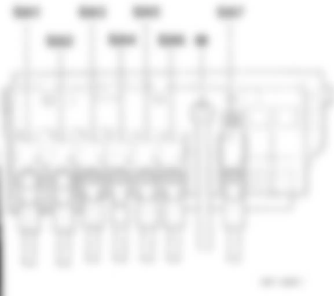
Audi A3 2007 - 1.19- FUSE PANEL C -SC- INSTRUMENT PANEL - LEFT SIDE
NOTE: The fuse panel C -SC- is located on the left side end of the dash panel (driver's side), refer to illustrations below.

Fig. 26: Audi A3 2007 - Component Locations - Fuse Panel C -SC- Instrument Panel - Left Side

1.19.1 - FUSE COLOR: For fuse identification and amperage rating refer to FUSE - COLOR CODES.
1.21 - POSITION OF FUSES ON FUSE PANEL, FROM MODEL YEAR 2006
Audi A3 2007 IDENTIFYING FUSES (INSTRUMENT PANEL - DRIVER'S SIDE - 2006)
Fuse
No.Rating
(Amperage)Function/Component Wiring
ID.Terminal 1 10A -Light Switch -E1
-Fuel Pump (FP) Relay -J17
-Engine Control Module (ECM) -J623 (1)
-Motronic Engine Control Module (ECM) -J220
-Diesel Direct Fuel Injection (DFI) Engine Control Module (ECM) -J248 (1)
-Fuel Pump (FP) Control Module -J538
-16-Pin Connector -T16- (Diagnostic Connector)SC1 15 2 5A -ABS Control Module -J104
-Brake Light Switch -F
-Brake Pedal Switch -F63SC2 15 3 5A -Airbag Control Module -J234
-Front Passenger Airbag Disabled Indicator Lamp -K145SC3 15 4 5A -Tire Pressure Monitoring Button -E226- (1)
-ASR/ESP Button -E256
-Back-up Light Switch -F4
-High Pressure Sensor -G65
-Air Quality Sensor -G238
-Oil Level Thermal Sensor -G266
-Heater Control Module -J162- (1)
-Left Rear Heated Seat Control Module -J215- (1)
-Right Rear Heated Seat Control Module -J216- (1)
-Drivers Heated Seat Control Module -J726- (1)
-Front Passengers Heated Seat Control Module -J727- (1)SC4 15 5 5A -Headlamp Range Control Module -J431 SC5 15 5 10A -Headlamp Adjuster -E102
-Left Headlamp Beam Adjustment Motor -V48- (1)
-Right Headlamp Beam Adjustment Motor -V49- (1)SC5 15 6 5A -Function Selection Switch 2 -E272- (1)
-Selector Lever -E313
-Tiptronic Switch -F189- (1)
-Power Steering Control Module -J500
-Data Bus On Board Diagnostic Interface -J533
-Direct Shift Gearbox (DSG) Mechatronic -J743SC6 15 7 5A -Garage Door Opener Control Head -E284
-Towing Recognition Control Module -J345- (1)
-Navigation System Control Module with CD drive -J401- (1)
-Navigation System Operating Electronics Control Module -J402
-Parking Aid Control Module -J446- (1)
-Garage Door Opener Control Module -J530
-Automatic Day/Night Interior Mirror -Y7SC7 15 8 10A -Trailer Socket -U10- (1) SC8 15 9 - Not used - - 10 5A -Seat Occupied Recognition Control Module -J706 SC10 15 11 5A -Right Headlamp Power Output Stage -J668 SC11 15 12 10A -Driver's Door Control Module -J386
-Front Passenger's Door Control Module -J387SC12 30 13 10A -Brake Light Switch -F- (brake lights)
-16-Pin Connector -T16- (Diagnostic Connector)SC13 30 14 5A -Transmission Control Module (TCM) -J217- (1) SC14 30 15 10A -Vehicle Electrical System Control Module -J519 SC15 30 16 10A -Rain/Light Recognition Sensor -G397
-Heater Control Module -J162
-Climatronic Control Module -J255
-Auxiliary Heater RF Receiver -R64SC16 30 17 5A -Comfort System Central Control Module -J393 SC17 30 18 5A -Selector Lever -E313
-Tiptronic Switch -F189- (1)
-Parking Aid Control Module -J446SC18 30 19 10A -Left Rear Door Control Module -J388
-Right Rear Door Control Module -J389SC19 30 20 5A -ABS Control Module -J104- (1) SC20 30 21 - Not used - - 22 40A -Fresh Air Blower Control Module -J126 SC22 30 23 30A -Driver's Window Regulator Motor -V147 SC23 30 24 20A -Cigarette Lighter -U1
-12V Socket -U5-SC24 30 25 30A -Heated Rear Window -Z1 SC25 30 26 20A -Socket -U SC26 30 27 15A -Fuel Pump (FP) 2 Relay -J49
-Fuel Pump (FP) Control Module -J538SC27 30 28 30A -Left Rear Window Regulator Motor -V26
-Right Rear Window Regulator Motor -V27SC28 30 29 10A -Mass Air Flow (MAF) Sensor -G70
-Positive Crankcase Ventilation (PCV) Heating Element -N79SC29 15 30 10A -Cylinder No. 1 Fuel Injector -N30
-Cylinder No. 2 Fuel Injector -N31
-Cylinder No. 3 Fuel Injector -N32
-Cylinder No. 4 Fuel Injector -N33
-Cylinder No. 5 Fuel Injector -N83
-Cylinder No. 6 Fuel Injector -N84SC30 15 31 5A -All-Wheel Drive Control Module -J492 SC31 15 31 20A -Vacuum Pump Relay -J57- (1) SC31 15 32 30A -Headlamp Washer Pump -V11
-Headlamp Washer Relay -J39SC32 15 33 25A -Power Sunroof Control Module -J245 SC33 30 34 20A -Left Rear Heated Seat Control Module -J215- (1)
-Right Rear Heated Seat Control Module -J216- (1)SC34 30 35 5A -Interior Monitoring Sensor -G273
-Vehicle Inclination Sensor -G384
-Alarm Horn -H12SC35 30 36 10A -Driver's Seat Lumbar Support Adjustment Switch -E176
-Front Passenger's Seat Lumbar Support Adjustment Switc -E177SC36 30 37 20A -Climatronic Control Module -J255
-Driver's Heated Seat Control Module -J726- (1)
-Front Passenger's Heated Seat Control Module -J727- (1)
-Front Left Heated Seat -Z45
-Front Right Heated Seat -Z46SC37 30 38 30A -Front Passengers Window Regulator Motor -V148- SC38 30 39 20A -Multi-Function Transmission Range (TR) Switch -F125- (1)
-Transmission Control Module (TCM)-J217- (1)SC39 15 40 NA -Fresh Air Blower Switch -E9- (1)
(Only models without A/C)SC40 75 41 15A -Rear Window Wiper Motor -V12 SC41 75 42 15A -Windshield and Rear Window Washer Pump -V59 SC42 75 43 - Not used - - 44 20A -Towing Recognition Control Module -J345- (1) SC44 30 45 15A -Towing Recognition Control Module -J345- (1) SC45 30 46 5A -Heater Control Module -J162- (1)
-Climatronic Control Module -J255
-Left Washer Nozzle Heater -Z20
-Right Washer Nozzle Heater -Z21SC46 75 47 5A -Left Headlamp Power Output Stage -J667 SC47 15 48 10A -Socket -U- (1)
(Only Driving School)SC48 30 49 5A -Special Purpose Vehicle Fuse 6 -S296- (1)
-Footwell Illumination Switch -E295- (1)
-Warning Buzzer Switch -S296- (1)SC49 15
(1) Not for models with US equipment.
1.22 - POSITION OF FUSES ON FUSE PANEL, FROM MODEL YEAR 2007
Audi A3 2007 IDENTIFYING FUSES (INSTRUMENT PANEL - DRIVER'S SIDE - 2007)
Fuse
No.Rating
(Amperage)Function/Component Wiring
ID.Terminal 1 10A -Light Switch -E1
-Headlamp Adjuster -E102- (1)
-Mass Air Flow (MAF) Sensor -G70- (BKC, BXE, AZV, BKD, BLS, BMM, BMN, BPU, BPT, BYZ, BWA, BPY, BHZ, BZB, CAWB, CBFA, BUY, CDAA, CCZA, CCTA, CDLA, CDLC, CAYB, CAYC, BZC, CBEA)
-Towing Recognition Control Module -J345- (1)
-Headlamp Range Control Module -J431
-Positive Crankcase Ventilation (PCV) Heating Element -N79- (BSE, BSF, BKC, BXE, AZV, BKD, BLS, BMM, BMN, BUB, BUY, CCSA, CBBB, CBAB, CBAA, CBRA, CAYB, CAYC, CBEA)
-16 Pin Connector -T16-(Diagnostic Connector)
-Left Headlamp Beam Adjustment Motor -V48- (1)
-Right Headlamp Beam Adjustment Motor -V49- (1)SC1 15 1 10A -Mass Air Flow (MAF) Sensor -G70- (CBBB, CBAB, CBAA)
Not applicable from model year 2010SC1 15 1 10A -Mass Air Flow (MAF) Sensor -G70- (CBBB, CBAB, CBAA)
(Only models without stop/start system)
Applicable from model year 2010SC1 15 1 10A -Stop/Start Mode Button -F416
(Only models with stop/start system)
Applicable from model year 2010SC1 15 2 10A -Engine Control Modules (ECM) -J...
-Fuel Pump (FP) Relay -J17-(BSE, BSF, BUB, CCSA, CBRA)
-ABS Control Module -J104
-SIMOS Control Module Power Supply Relay -J363-(BSE, BSF, CCSA)- (1)
-Power Steering Control Module -J500
-Data Bus On Board Diagnostic Interface -J533
-Fuel Pump (FP) Control Module -J538-(BPU, BYT, BPT, BLF, BVY, BVZ, BPY, BWA, BHZ, CAXC, BZB, CAWB, CBFA, CDAA, CCZA, CCTA, CDLC, CDLA, BZC)
-Selector Lever Sensors Control Module -J587
-Direct Shift Gearbox (DSG) Mechatronic -J743SC2 15 2 10A -Brake Light Switch -F
-Brake Pedal Switch -F63
Not applicable from model year 2010SC2 15 2 10A -Tiptronic Switch -F189- (1)
-All Wheel Drive Control Module -J492
Not applicable from model year 2009SC2 15 2 10A -Starter Relay 1 -J906
-Starter Relay 2 -J907
-Automatic Day/Night Interior Mirror Relay -J910
(Only models with stop/start system)
Applicable from model year 2010SC2 15 3 5A -Airbag Control Module -J234
-Front Passenger Airbag Disabled Indicator Lamp -K145SC3 15 4 5A -Left Rear Heated Seat Regulating Switch -E128- (1)
-Right Rear Heated Seat Regulating Switch -E129- (1)
-Tire Pressure Monitoring Button -E226- (1)
-ASR/ESP Button -E256
-Garage Door Opener Control Head -E284
-Garage Door Opener Control Module -J530
-Back-up Light Switch -F4
-High Pressure Sensor -G65
-Air Quality Sensor -G238
-Oil Level Thermal Sensor -G266
-Heater Control Module -J162
-Climatronic Control Module -J255
-A/C Control Module -J301- (1)
-Navigation System Control Module with CD drive -J401- (1)
-Parking Aid Control Module -J446
-Seat Occupied Recognition Control Module -J706
-Drivers Heated Seat Control Module -J726- (1)
-Front Passengers Heated Seat Control Module -J727- (1)
-Left Washer Nozzle Heater -Z20
-Right Washer Nozzle Heater -Z21SC4 15 4 5A -Automatic Day/Night Interior Mirror -Y7
Not applicable from model year 2010SC4 15 4 5A -Automatic Day/Night Interior Mirror -Y7
(Only models without stop/start system)
Applicable from model year 2010SC4 15 4 5A -Voltage Stabilizer -J532
(Only models with stop/start system)
Applicable from model year 2010SC4 15 5 5A -Left Headlamp Power Output Stage -J667 SC5 15 6 5A -Right Headlamp Power Output Stage -J668 SC6 15 7 - Not used - - 8 5A -Instrument Cluster Control Module -J285
Applicable from model year 2010SC8 30 9 15A -Navigation System Operating Electronics Control Module -J402
-Radio/Navigation Display Control Module -J503
-Radio -R
-8 Pin Connector -T8-(Preparation for Radio)- (1)
Applicable from model year 2010SC9 30 10 7.5A -Navigation System Tuner, TV -J415- (1)
-Telephone Transceiver -R36
-Satellite Radio -R146- (2)
-External Audio Source Connector -R199
-18 Pin Connector -T18a- (VDA-Interface) (1)
Applicable from model year 2010SC10 30 11 10A -Automatic Day/Night Interior Mirror Relay -J910
-Automatic Day/Night Interior Mirror -Y7
(Only models with stop/start system)
Applicable from model year 2010SC11 30 12 10A -Driver's Door Control Module -J386
-Front Passenger's Door Control Module -J387SC12 30 13 10A -Left Rear Door Control Module -J388
-Right Rear Door Control Module -J389SC13 30 13 10A -Comfort System Central Control Module -J393
Not applicable from model year 2010SC13 30 14 10A -ABS Control Module -J104
-Selector Lever Sensors Control Module -J587SC14 30 14 10A -Tiptronic Switch -F189- (1)
-Transmission Control Module (1CM) -J217- (1)
-Parking Aid Control Module -J446
Not applicable from model year 2009SC14 30 15 10A -Front Interior Light -W
-Front Interior Light -W1
-Rear Interior Light -W43SC15 30 16 10A -Rain/Light Recognition Sensor -G397
-Heater Control Module -J162
-Climatronic Control Module -J255
-A/C Control Module -J301- (1)
-Tire Pressure Monitoring Control Module -J502- (2)
-Auxiliary Heater RF Receiver -R64- (1)
-16 Pin Connector -T16-(Diagnostic Connector)SC16 30 16 10A -Light Switch -E1
Applicable from model year 2010SC16 30 17 5A -Interior Monitoring Sensor -G273- (1)
-Vehicle Inclination Sensor -G384- (1)
-Alarm Horn -H12SC17 30 18 5A -Engine Control Module (ECM) -J623- (Diagnosis Wire)
(Only models with engine code CBFA)
Not applicable from model year 2010SC18 50 18 5A -Vehicle Electrical System Control Module -J519- (Diagnosis Wire)
-Voltage Stabilizer -J532-(Diagnosis Wire)
-Engine Control Module (ECM) -J623-(Diagnosis Wire)
(Only models with stop/start system)
Applicable from model year 2010SC18 50 19 10A -All Wheel Drive Control Module -J492
Applicable from model year 2009SC19 30 20 5A -Electronic Damping Control Module -J250
Applicable from model year 2009SC20 30 21 - Not used - - 22 40A -Fresh Air Blower Control Module -J126
-Fresh Air Blower -V2SC22 30 23 30A -Driver's Window Regulator Motor -V147 SC23 30 24 20A -Cigarette Lighter -U1 SC24 30 25 30A -Heated Rear Window -Z1 SC25 30 26 20A -Socket -U SC26 30 27 15A -Fuel Pump (FP) Relay -J17- (BSE, BSF, CCSA, CBBB, CBAB, CBAA, BKC, BXE, AZV, BKD, BLS, BMM, BUY, BMN, CAYB, CAYC, CBEA)
-Fuel Pump (FP) Control Module -J538- (BPU, BYT, BPT, BWA, BPY, BHZ, CAXC, BZB, CAWB, CCTA, CBFA, BLF, BVY, BVZ, CDAA CCZA, CDLA, CDLC, BZC)SC27 30 27 15A -Fuel Pump (FP) 2 Relay -J49- (BSE, BSF. BUB, CCSA, CBRA)
-Applicable from November 2006, only models with auxiliary heater, engine codes: BKC, BXE, AZV, BKD, BLS, BMM, BUY, BMN, CBBB, CBAB, CBAA, CAYB,CAYC.SC27 30 27 15A -Auxiliary Fuel Pump Relay -J832- (CBBB, CBAB, CBAA, CBEA)
-Auxiliary Fuel Pump -V393- (CBBB, CBAB, CBAA, CBEA)SC27 30 28 30A -Left Rear Window Regulator Motor -V26
-Right Rear Window Regulator Motor -V27SC28 30 29 - Not used - - 30 20A -Multi-Function Transmission Range (TR) Switch -F125- (1)
-Transmission Control Module (TCM) -J217- (1)
Not applicable from model year 2009SC30 15 31 20A -Brake System Vacuum Pump -V192
(CCSA, BSE, BSF) (1)SC31 15 32 30A -Headlamp Washer Pump -V11 SC32 30 33 20A -Power Sunroof Control Module -J245 SC33 30 34 20A -Left Rear Heated Seat Control Module -J215- (1)
-Right Rear Heated Seat Control Module -J216- (1)SC34 30 35 - Not used - - 36 10A -Driver's Seat Lumbar Support Adjustment Switch -E176
-Front Passenger's Seat Lumbar Support Adjustment Switc -E177SC36 30 37 20A -Climatronic Control Module -J255
-Driver's Heated Seat Control Module -J726- (1)
-Front Passenger's Heated Seat Control Module -J727- (1)SC37 30 38 30A -Front Passengers Window Regulator Motor -V148 SC38 30 39 5A -Models Location System Control Module Interface -J843 (Special Functions Interface) SC39 30 39 25A Radio/Navigation Display Control Module -J503- (1)
Only with radio/navigation system Japan
Applicable from model year 2010SC39 30 40 40A -Fresh Air Blower Switch -E9- (1)
-Fresh Air Blower -V2- (1)
Not applicable from model year 2009SC40 75 40 40A -Starter -B
Applicable from model year 2009SC40 15 41 15A -Rear Window Wiper Motor -V12
Not applicable from model year 2009SC41 75 41 15A -Rear Window Wiper Motor -V12
Applicable from model year 2009SC41 15 42 15A -Windshield and Rear Window Washer Pump -V59
Not applicable from model year 2009SC42 75 42 15A -Windshield and Rear Window Washer Pump -V59
Applicable from model year 2009
Not applicable from model year 2010SC42 15 43 - -Comfort System Central Control Module -J393
Not applicable from model year 2010- - 43 - -Vehicle Electrical system Control Module -J519
Applicable from model year 2010- - 44 20A -Towing Recognition Control Module -J345- (1) SC44 30 45 20A -Towing Recognition Control Module -J345- (1)
Not applicable from November 2006SC44 30 45 15A -Towing Recognition Control Module -J345- (1)
Applicable from November 2006SC45 30 46 5A -Trailer Socket-U10 (1) SC46 15 47 5A -18 Pin Connector -T18a- (VDA-Interface) (1) SC47 15 47 5A -Amplifier for telephone -R86- (1)
Applicable from model year 2010SC47 15 48 10A -Socket -U- (1)
(Only Driving School)SC48 30 49 5A -Warning Buzzer -H3- (Driving School) (1)
-Special Purpose Vehicle Fuse 6 -S296- (Criminal Investigation/Doctor on Call Models) (1)
-Driving School Footwell Illumination -W56- (1)SC49 15
(1) Not for models with US equipment.
(2) Only for models with US equipment.
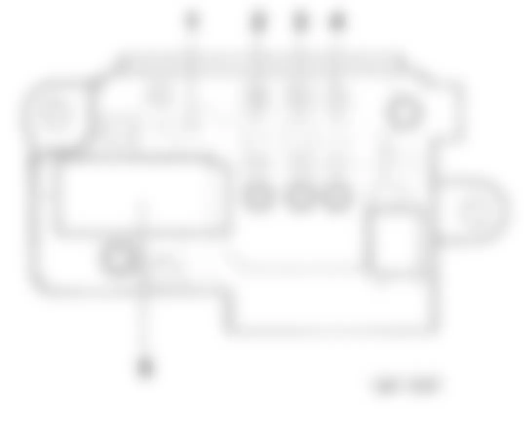
Audi A3 2007 - 1.23 - MAIN FUSE PANEL D -SD- IN LUGGAGE COMPARTMENT, RIGHT REAR
NOTE: This luggage compartment relay/fuse panel is located behind the trim on the right side of trunk, refer to illustrations below. For relay identification, refer to 1.11- POSITION OF RELAYS ON MAIN FUSE PANEL, IN LUGGAGE COMPARTMENT - RIGHT REAR under RELAY INDEX INFORMATION. For fuse identification and amperage rating refer to FUSE - COLOR CODES.
1.23.1 - POSITION OF FUSES:
Audi A3 2007 IDENTIFYING FUSES (LUGGAGE COMPARTMENT - RIGHT SIDE - FROM MODEL YEAR 2006)
Position/
LocationRating
(Amperage)Function/Component Wiring
IDTerminal 1 5A Vehicle Electrical System Control Module -J519- SF1 30 2 125A Electronics Box High Main Fuse Panel Supply,
Relay and Fuse Carrier Electronics Box HighSF2 30 3 80A Electronics Box High Main Fuse Panel Supply,
Relay and Fuse Carrier Electronics Box HighSF3 30 4 30A Amplifier -R12-
Only models with BOSE system
Not applicable from November 2005SF4 30 4 50A Doctor Option
Not applicable from November 2005SF4 30 4 30A Fuses Supply:
-SCI2- through -SC17-, -SC19-
Applicable from November 2005SF4 30 4 30A Fuses Supply:
SC12- through SC17-, -SC43-
Applicable from May 2006SF4 30
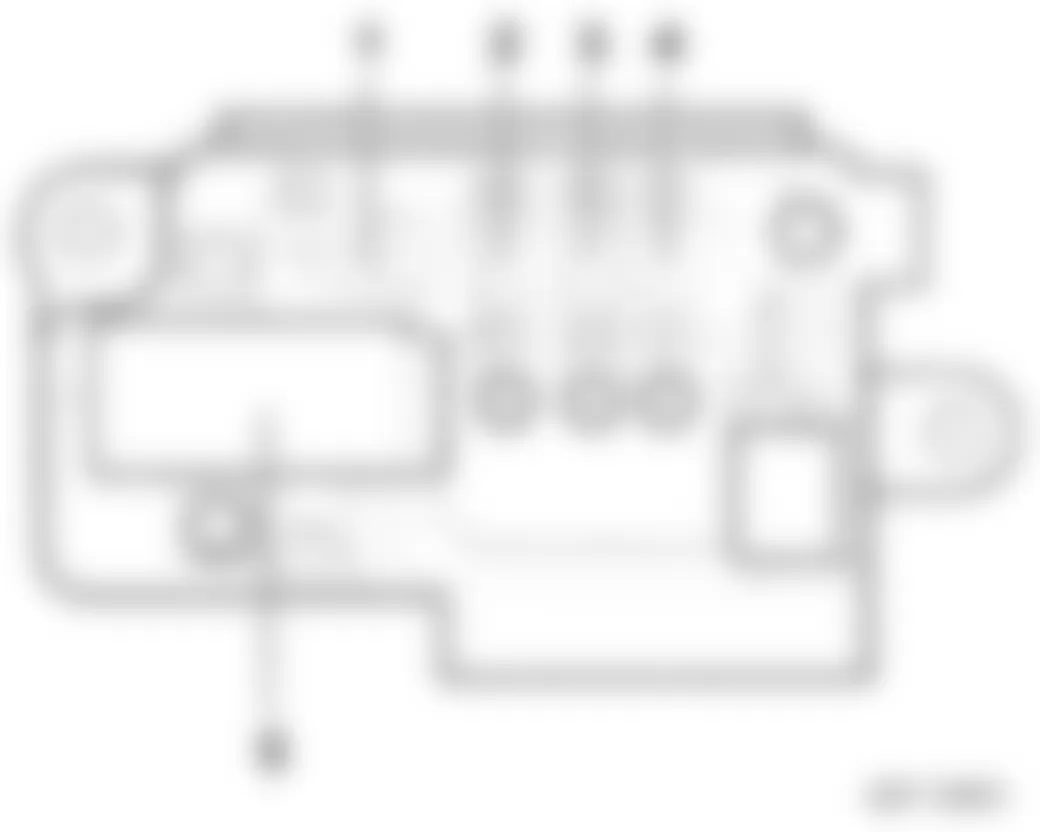
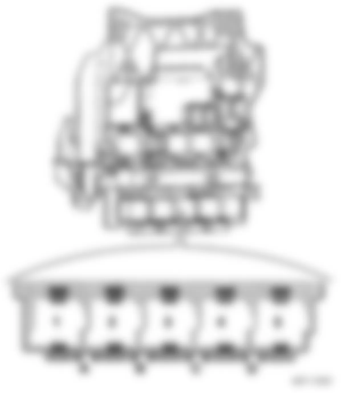
Audi A3 2007 - 1.26- FUSES UNDER INSTRUMENT PANEL, LEFT SIDE (FROM MODEL YEAR 2006)
NOTE: This relay/fuse panel is located below the instrument panel, driver's side, refer to illustrations below. For relay identification, refer to 1.7- POSITION OF RELAYS UNDER INSTRUMENT PANEL, LEFT SIDE (FROM MODEL YEAR 2006) under RELAY INDEX INFORMATION. For fuse identification and amperage rating refer to FUSE - COLOR CODES.
Fig. 28: Audi A3 2007 - Component Locations - Relay/Fuse Panel Under Instrument Panel - Left Side

POSITION OF FUSES, FROM MODEL YEAR 2006:
Audi A3 2007 IDENTIFYING FUSES (UNDER INSTRUMENT PANEL, LEFT SIDE - FROM MODEL YEAR 2006)
Position/Location Rating (Amps) Function/Component A - Not used B - Not used C 30A Fuse 1 -S131- D - Not used
Audi A3 2007 - RELAY INDEX INFORMATION 1.2- POSITION OF RELAYS ON ELECTRONICS BOX LOW (FROM MODEL YEAR 2006)
NOTE: Located in engine compartment, left side.

Audi A3 2007 IDENTIFYING RELAYS (ON ELECTRONICS BOX LOW - FROM MODEL YEAR 2006)
Position/Location Function/Component 1 Motronic Engine Control Module (ECM) Power Supply Relay -J271-
1 Power Supply Relay (Terminal 30) -J317-
1 SIMOS Control Module Power Supply Relay -J363-
2 Connection Bridge, Automatic Glow Time Control Module
2 Secondary Air Injection (AIR) Pump Relay -J299-
2 Engine Component Power Supply Relay -J757-
(1) - Engine Component Power Supply Relay -J757- in 1.7- POSITION OF RELAYS UNDER INSTRUMENT PANEL, LEFT SIDE (FROM MODEL YEAR 2006).
(2) - Engine Component Power Supply Relay -J757- in 1.8- POSITION OF RELAYS UNDER INSTRUMENT PANEL, LEFT SIDE (FROM MODEL YEAR 2009)
Audi A3 2007 - 1.4- POSITION OF RELAYS ON ELECTRONICS BOX HIGH (FROM MODEL YEAR 2006)
NOTE: Located in engine compartment, left side.
Audi A3 2007 IDENTIFYING RELAYS (ON ELECTRONICS BOX HIGH - FROM MODEL YEAR 2006)
Position/Location Function/Component Connection 1 Motronic Engine Control Module (ECM) Power Supply Relay -J271-
R1 2 Coolant Circulation Pump Relay -J151-
R2 3 Fuel Pump (FP) Relay -J17-
R4 3 Engine Component Power Supply Relay -J757-
R4 4 Not used
R3
Audi A3 2007 - 1.5- POSITION OF RELAYS, RELAY CARRIER ON VEHICLE ELECTRICAL SYSTEM CONTROL MODULE (FROM MODEL YEAR 2006)
NOTE: Located under instrument panel, left side.
Audi A3 2007 IDENTIFYING RELAYS (RELAY CARRIER - UNDER INSTRUMENT PANEL LEFT SIDE - FROM MODEL YEAR 2006)
Position/Location Function/Component Connection 1 Power Supply Relay 2 (terminal 15) -J681- B1 2 Not used B2 3 Rear Window Defogger Relay -J9- B5 4 Horn Relay -J413- B6 5 Load Reduction Relay -J59- B9 6 Dual Washer Pump Relay 1 -J729- B8 7 Dual Washer Pump Relay 2 -J730- B7 8 Not used B3 9 Power Supply Relay 2 (terminal 30) -J689- B4
Audi A3 2007 - 1.6- POSITION OF RELAYS, RELAY CARRIER ON VEHICLE ELECTRICAL SYSTEM CONTROL MODULE (FROM MODEL YEAR 2010)
NOTE: Located under instrument panel, left side.
Audi A3 2007 IDENTIFYING RELAYS (RELAY CARRIER - UNDER INSTRUMENT PANEL LEFT SIDE - FROM MODEL YEAR 2010)
Position/Location Function/Component 1 Power Supply Relay 2 (terminal 15) -J681- 2 Rear Window Defogger Relay -J9- 3 Horn Relay -J413-
Headlamp Washer Relay -J39- 4 Load Reduction Relay -J59- 5 Preheating Coolant, High Heat Output Relay -J360- (1)
(1) Only models with auxiliary air heater.
Audi A3 2007 - 1.7- POSITION OF RELAYS UNDER INSTRUMENT PANEL, LEFT SIDE (FROM MODEL YEAR 2006)
NOTE: This relay and fuse holder is located below instrument panel on driver's side, refer to illustration below. For fuse identification, refer to 1.26- FUSES UNDER INSTRUMENT PANEL, LEFT SIDE (FROM MODEL YEAR 2006) under FUSE INDEX INFORMATION.

Audi A3 2007 IDENTIFYING RELAYS (UNDER INSTRUMENT PANEL, LEFT SIDE - FROM MODEL YEAR 2006)
Position/Location Function/Component Connection 1 Headlamp Washer Relay -J39- - 2 Fuel Pump (FR) Relay -J17-
2.1 2 Fuel Pump (FP) 2 Relay -J49-
2.1 2 Fuel Pump (FR) Relay -J17-
2.1 2 Fuel Pump (FP) 2 Relay -J49-
2.2 2 Fuel Pump (FR) Relay -J17-
2.2 2 Preheating Coolant, Low Heat Output Relay -J359-
- 3 Power Supply Relay (terminal 50) -J682-
- 3 Preheating Coolant, High Heat Output Relay -J360-
- 4 Power Supply Relay (terminal 50) -J682-
- 4 Engine Power Reduction Relay 2 -J663-
- 5 Fuel Pump (FP) 2 Relay -J49-
5.1 5 Coolant Circulation Pump Relay -J151-
5.1 5 Fuel Pump (FP) Relay -J17-
5.1 5 Engine Component Power Supply Relay -J757-
5.2 5 Fuel Pump (FP) 2 Relay -J49-
5.2 5 Fuel Pump (FP) Relay -J17-
5.2 5 Engine Power reduction Relay1 -J662-
-
(1) - Fuel Pump (FR) Relay -J17- in 1.4- POSITION OF RELAYS ON ELECTRONICS BOX HIGH (FROM MODEL YEAR 2006)
(2) Only models with auxiliary heater.
Audi A3 2007 - 1.8- POSITION OF RELAYS UNDER INSTRUMENT PANEL, LEFT SIDE (FROM MODEL YEAR 2009)
NOTE: This relay and fuse holder is located below instrument panel driver's side on relay / fuse panel with Vehicle Electrical System Control Module -J519- and threaded connection. - illustration below. For fuse identification, refer to 1.26- FUSES UNDER INSTRUMENT PANEL, LEFT SIDE (FROM MODEL YEAR 2006) under FUSE INDEX INFORMATION.
Fig. 34: Audi A3 2007 - Component Locations - Position Of Relays Under Instrument Panel Left Side

Audi A3 2007 IDENTIFYING RELAYS (UNDER INSTRUMENT PANEL, LEFT SIDE - FROM MODEL YEAR 2009)
Position/Item Function/Component 1 Preheating Coolant, Low Heat Output Relay -J359-
2 Power Supply Relay (terminal 50) -J682-
3 Auxiliary Fuel Pump Relay -J832-
3 Starter Relay 1 -J906-
3 Headlamp Washer Relay -J39-
3 Starter Relay 1 -J907-
4 Fuel Pump (FR) Relay -J17-
4 Fuel Pump (FP) 2 Relay -J49-
4 Coolant Circulation Pump Relay -J151-
4 Fuel Pump (FP) 2 Relay -J49-
4 Engine Component Power Supply Relay -J757-
5 Preheating Coolant, High Heat Output Relay -J360-
5 Automatic Day/Night Interior Mirror Relay -J910-
5 Auxiliary Fuel Pump Relay -J832-
(1) - item 5 "Auxiliary Fuel Pump Relay -J832-" this table.
(2) - "Headlamp Washer Relay -J39-" under 1.6- POSITION OF RELAYS, RELAY CARRIER ON VEHICLE ELECTRICAL SYSTEM CONTROL MODULE (FROM MODEL YEAR 2010).
(3) - "Fuel Pump (FR) Relay -J17-" under 1.4- POSITION OF RELAYS ON ELECTRONICS BOX HIGH (FROM MODEL YEAR 2006).
(4) - "Coolant Circulation Pump Relay -J151-" under 1.4- POSITION OF RELAYS ON ELECTRONICS BOX HIGH (FROM MODEL YEAR 2006).
(5) - "Preheating Coolant, High Heat Output Relay -J360-" under 1.6- POSITION OF RELAYS, RELAY CARRIER ON VEHICLE ELECTRICAL SYSTEM CONTROL MODULE (FROM MODEL YEAR 2010).
Audi A3 2007 - 1.9- POSITION OF RELAYS UNDER ELECTRONIC BOX (Up TO 2006)
NOTE: Relays carrier under electronic box in engine compartment left side. - illustration below.
Fig. 35: Audi A3 2007 - Component Locations - Position Of Relays Under Electronics Box
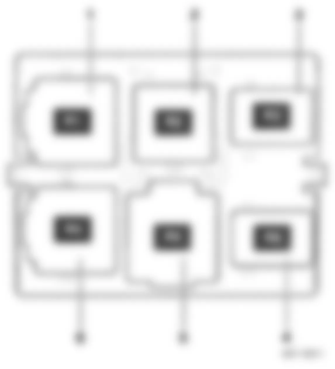
Audi A3 2007 IDENTIFYING RELAYS (UNDER ELECTRONIC BOX - ENGINE COMPARTMENT - LEFT SIDE - UP TO 2006)
Position/Location Function/Component 1 Not used 2 Automatic Glow Time Control Module -J179-
3 Not used 4 Coolant Circulation Pump Relay -J151-
5 Secondary Air Injection (AIR) Pump Relay -J299- 6 Not used
(1) For model year 2006 up, refer to "Automatic Glow Time Control Module -J179-" under 1.10- POSITION OF RELAYS UNDER ELECTRONIC BOX (2006 & Up).
(2) For model year 2006, refer to "Secondary Air Injection (AIR) Pump Relay -J299-" under 1.2- POSITION OF RELAYS ON ELECTRONICS BOX LOW (FROM MODEL YEAR 2006).
(3) For model year 2009 up, refer to "Secondary Air Injection (AIR) Pump Relay -J299-" under 1.10- POSITION OF RELAYS UNDER ELECTRONIC BOX (2006 & Up).
Audi A3 2007 - 1.10- POSITION OF RELAYS UNDER ELECTRONIC BOX (2006 & Up)
NOTE: Relays carrier under electronic box in engine compartment left side. - illustration below.
NOTE: Relay carrier is only visible when the electronics box is removed.
Fig. 36: Audi A3 2007 - Component Locations - Relay Position Under Electronics Box

Audi A3 2007 IDENTIFYING RELAYS (UNDER ELECTRONICS BOX LOW - FROM MODEL YEAR 2006)
Position/Location Function/Component 1 Relay Carrier under Electronics Box, in engine compartment left side 2 Automatic Glow Time Control Module -J179- 2 Not used
Audi A3 2007 IDENTIFYING RELAYS (UNDER ELECTRONICS BOX HIGH - FROM MODEL YEAR 2009)
Position/Location Function/Component 1 Relay Carrier under Electronics Box, in engine compartment, left side 2 Not used 2 Secondary Air Injection (AIR) Pump Relay -J299-
Audi A3 2007 - 1.11- POSITION OF RELAYS ON MAIN FUSE PANEL, IN LUGGAGE COMPARTMENT - RIGHT REAR
NOTE: This luggage compartment fuse holder is located behind the trim on the right side of trunk, refer to illustrations below. For fuse identification, refer to 1.23 - MAIN FUSE PANEL D -SD- IN LUGGAGE COMPARTMENT, RIGHT REAR under FUSE INDEX INFORMATION.
Audi A3 2007 IDENTIFYING RELAYS (ON MAIN FUSE PANEL, IN LUGGAGE COMPARTMENT - RIGHT REAR)
Position/Location Function/Component 5 Battery Switch-Off Relay -J655- 5 Battery Interrupt Igniter -N253-