
Audi A4 1998 - ENGINES 1.8L 4-Cylinder Turbo, AEB & ATW Engines
Audi A4 1998 - ENGINE IDENTIFICATION
NOTE: For engine repair procedures not covered in this article, see ENGINE OVERHAUL PROCEDURES - GENERAL INFORMATION article in the GENERAL INFORMATION section.
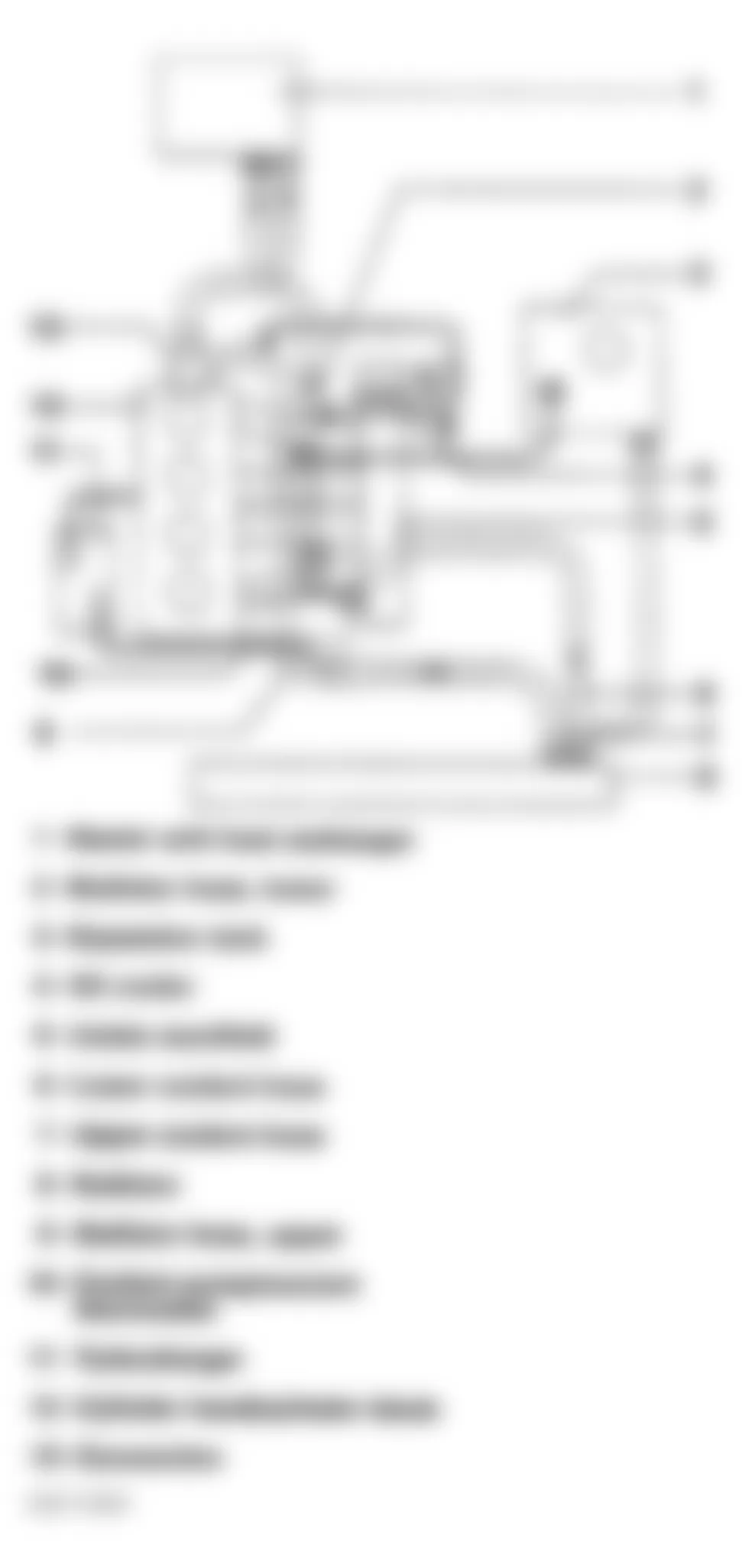
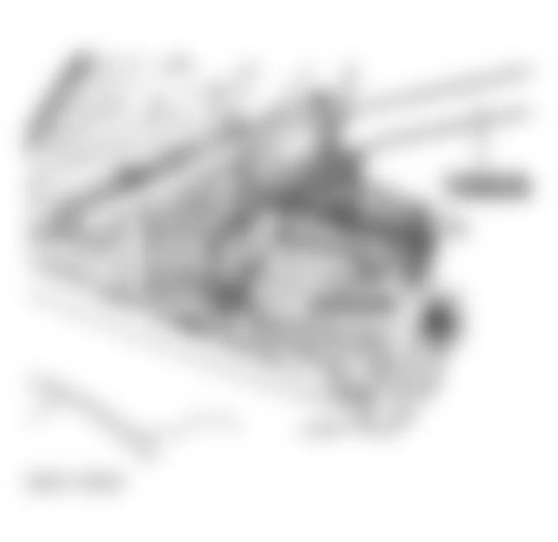
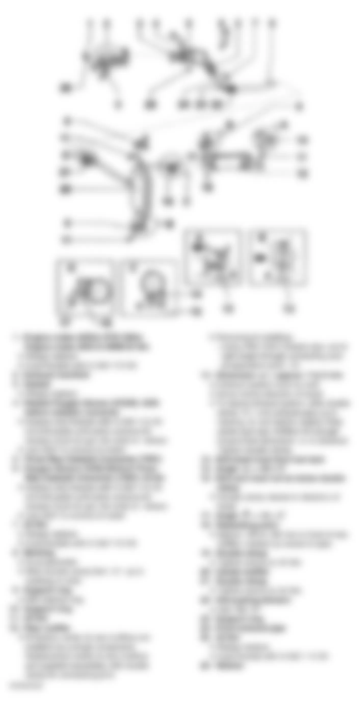
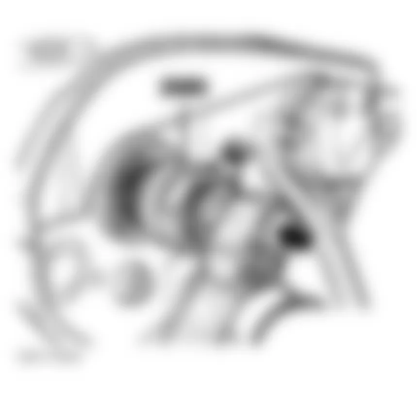
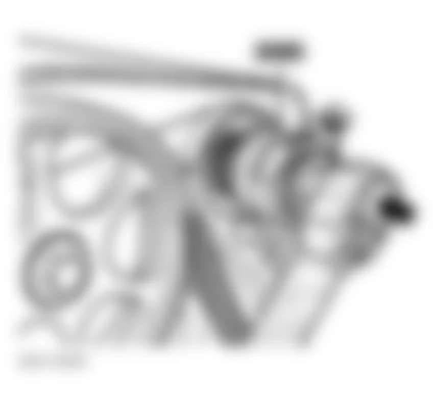
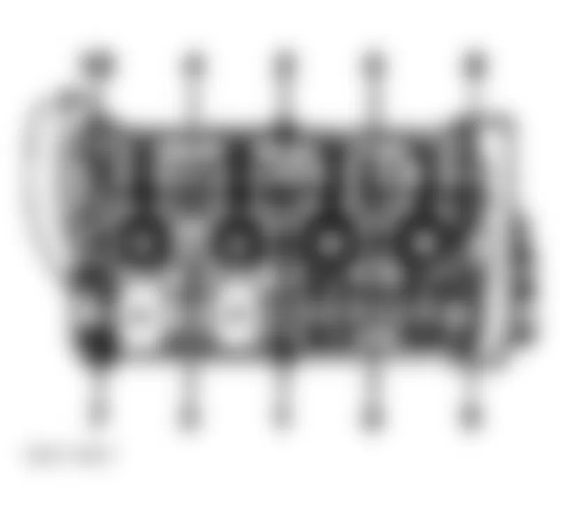
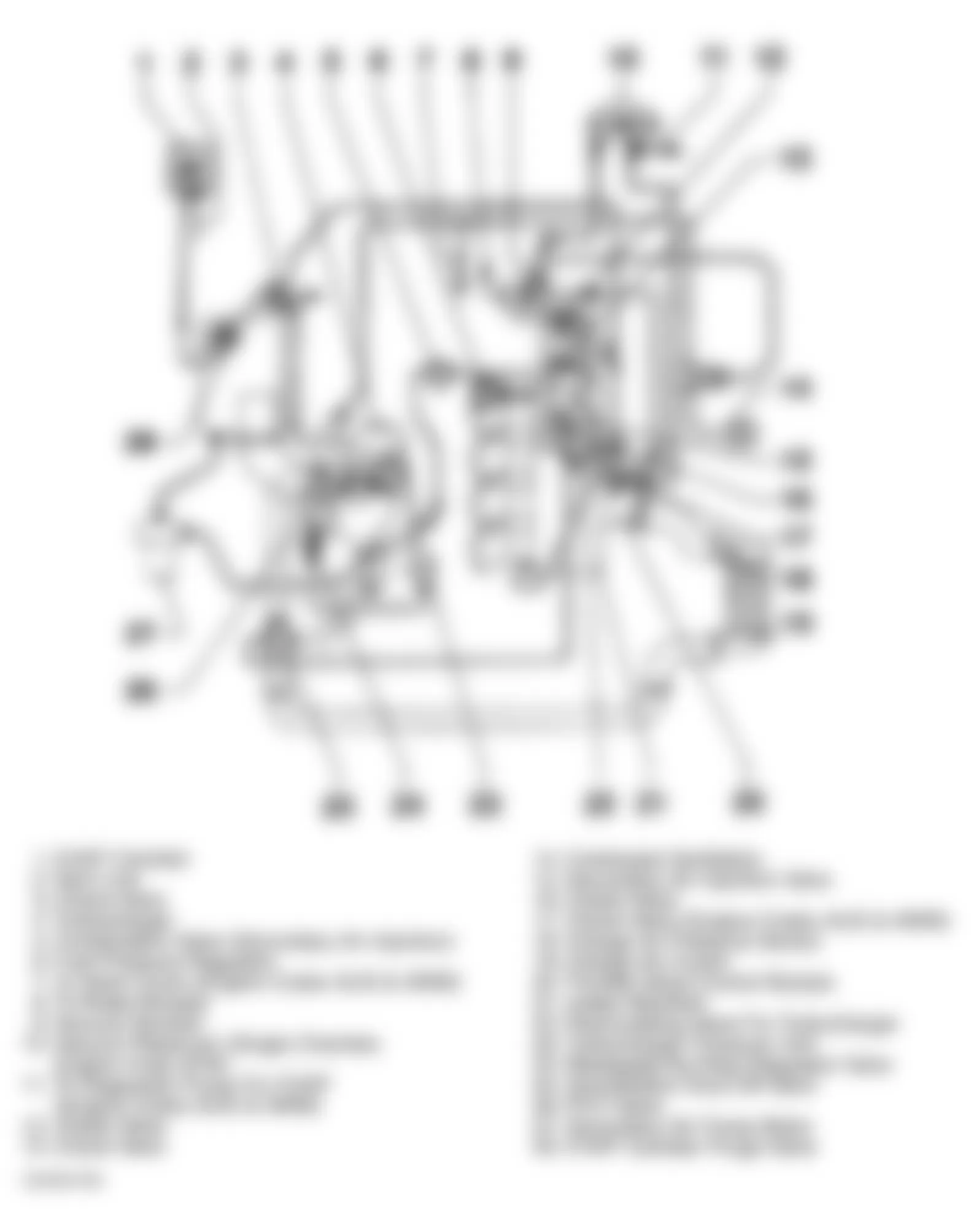
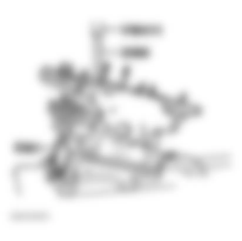
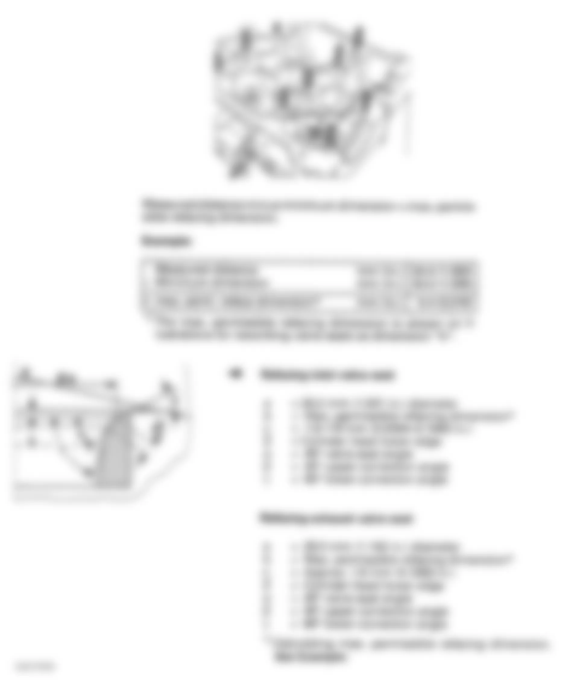
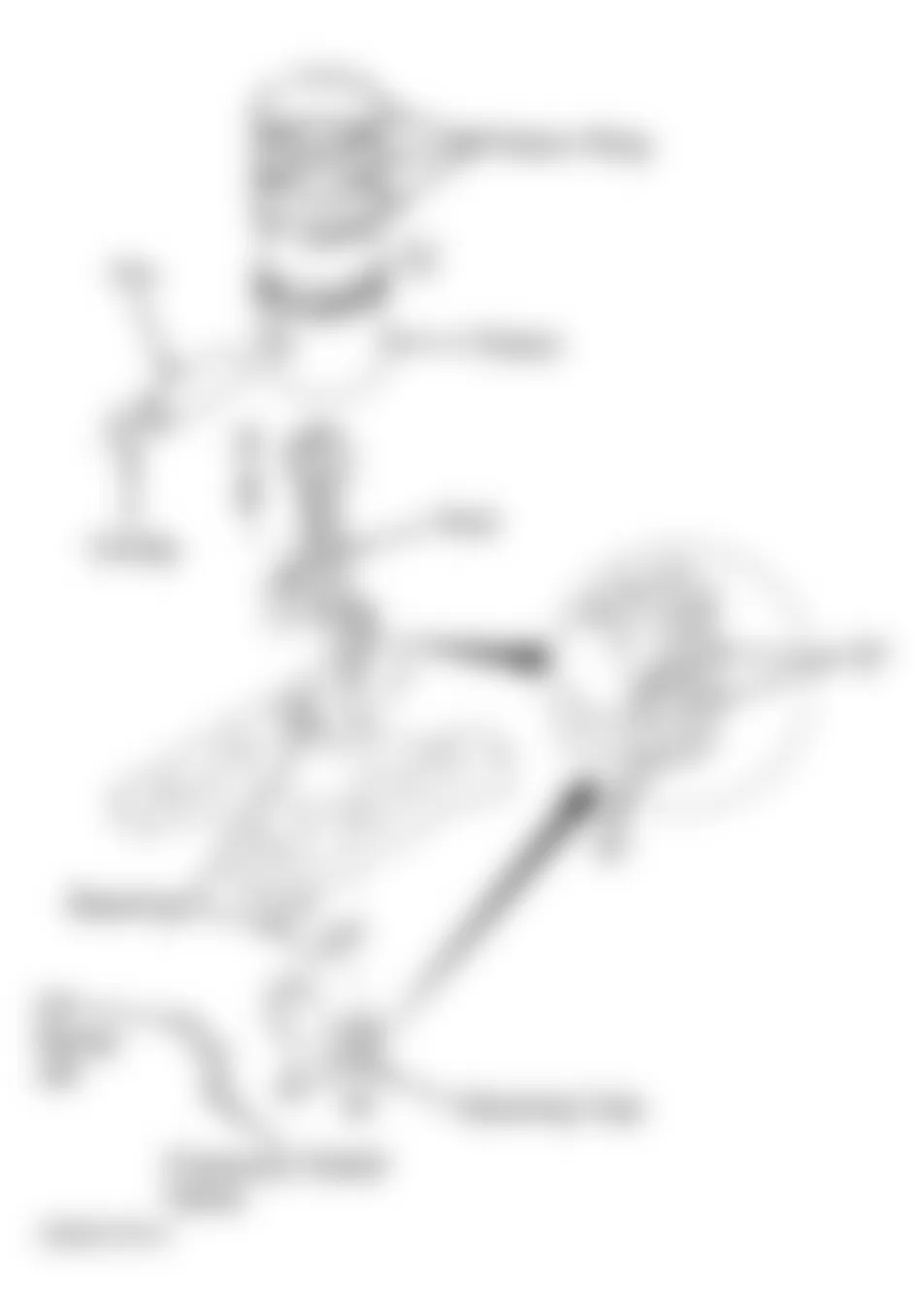
Engine identification number is stamped on a machined pad on front of engine block, below cylinder head. See Fig. 1.
Audi A4 1998 ENGINE CODES
Application Code Audi A4 1997-1999 AEB 2000 ATW Volkswagen Passat 1997-1999 AEB 2000 ATW
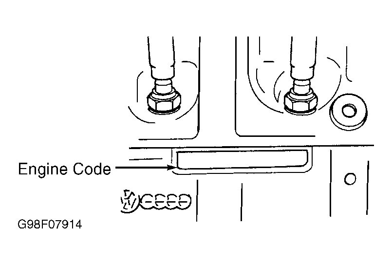
Fig. 1: Audi A4 1998 - Component Locations - Locating Engine Identification Number
Audi A4 1998 - ON-VEHICLE SERVICE THERMOSTAT Removal & Installation
WARNING: The cooling system is pressurized when the engine is warm. When opening the expansion tank, wear gloves and other appropriate protection, cover the cap with a cloth and open carefully to relieve system pressure slowly.
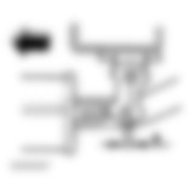
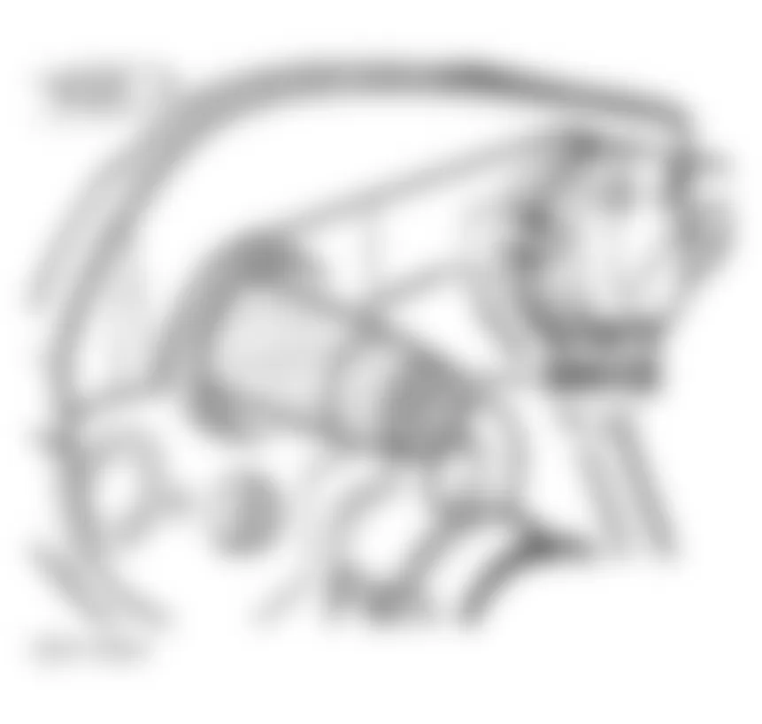
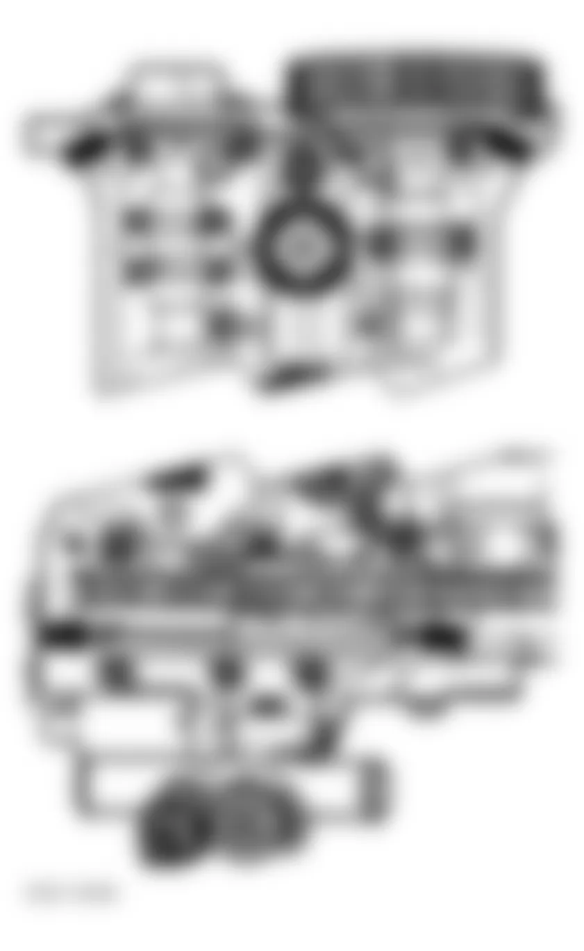
- Raise vehicle, remove lower engine shield (noise insulator). See Fig. 2. Drain coolant. See DRAINING COOLING SYSTEM.
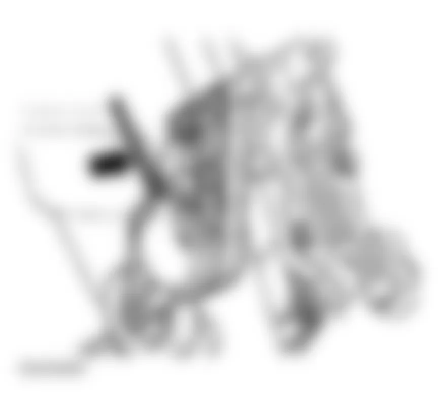
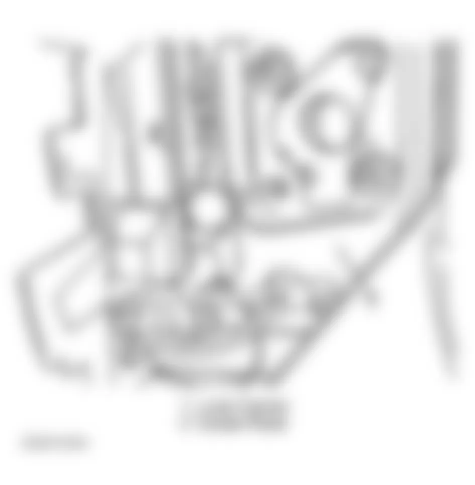
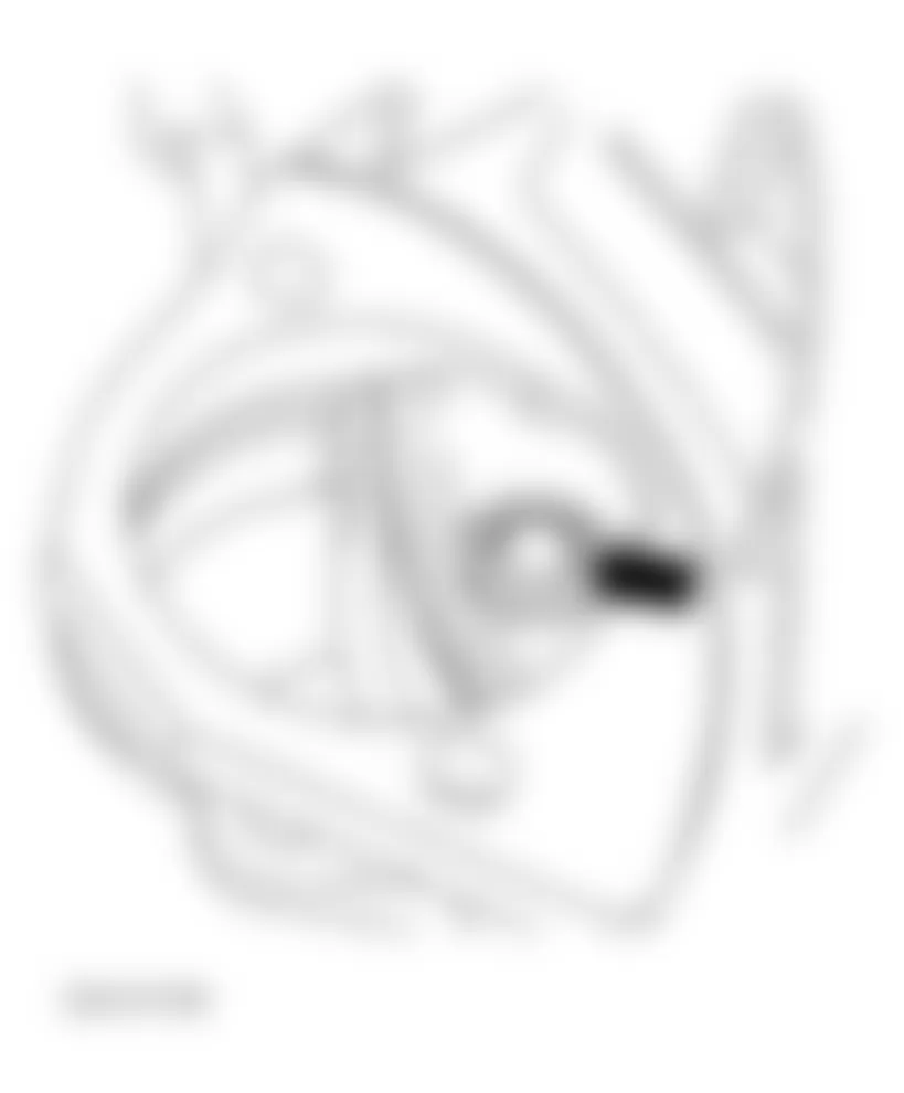
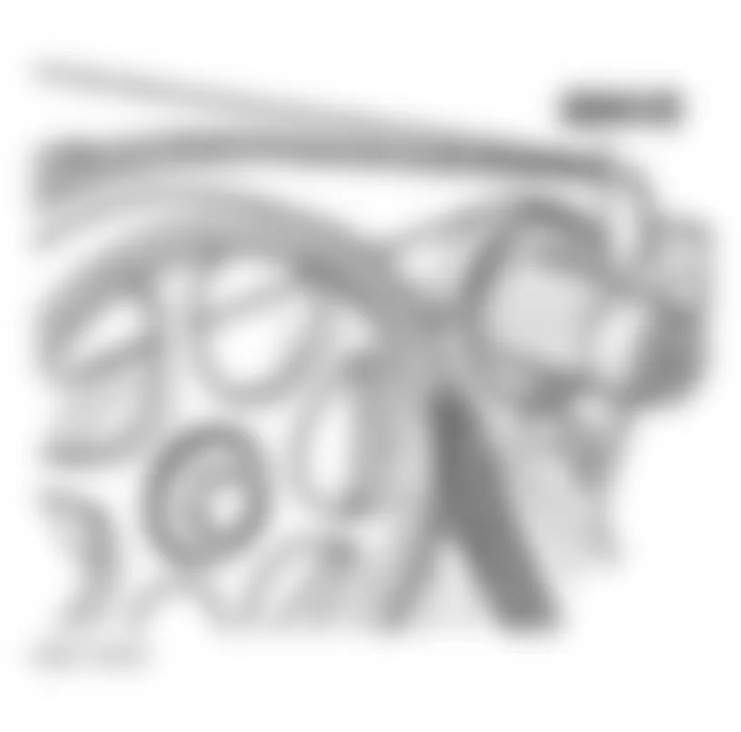
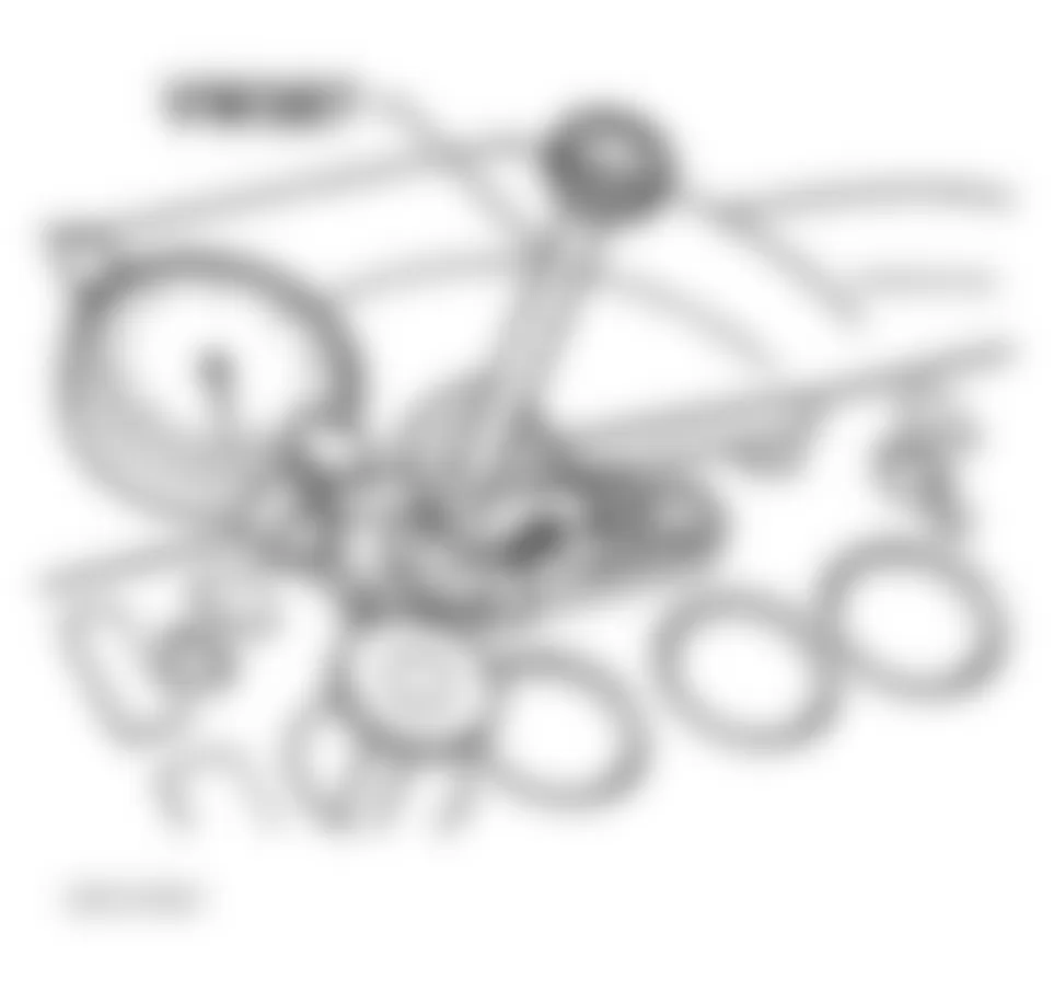
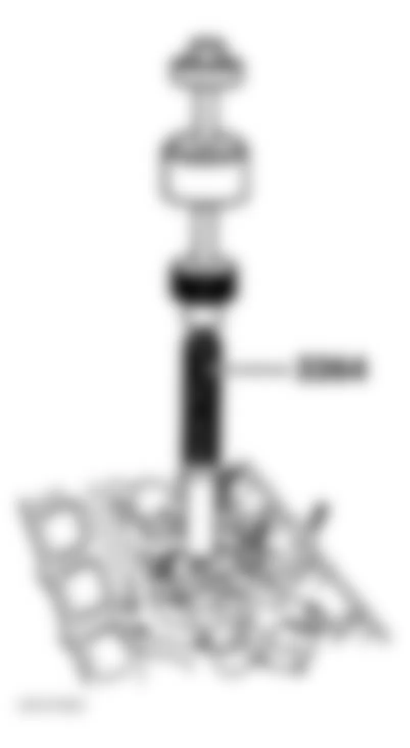
- Thermostat is located at the bottom of water pump housing. See Fig. 3. Remove bolts from thermostat cover, remove thermostat.
- Clean mating surfaces. Lube new O-ring gasket with coolant. Install thermostat. Tighten thermostat housing bolts to 7 ft. lbs (10 Nm). To install, reverse removal procedure. Fill and bleed cooling system. See COOLING SYSTEM BLEEDING.
Fig. 3: Audi A4 1998 - Component Locations - Identifying Location Of Thermostat & Coolant Drain Plug
Audi A4 1998 - WATER PUMP
CAUTION: Coolant/water mixture should be used at all times. Use only ethylene glycol based (phosphate-free) coolant.
NOTE: Water pump is located behind accessary drives, this will require accessory drive belts, generator, P/S pump, fan, pulleys and lower timing belt cover to be removed.
Audi A4 1998 - Removal & Installation
- Disconnect negative battery cable. Raise vehicle, remove lower engine shield (noise insulator). See Fig. 2. Remove complete front bumper assembly. Disconnect all necessary electrical connectors from front of vehicle.
- Attach Alignment Tools to chassis. Remove bolts securing front of body to vehicle. Slide front of body forward onto alignment tool. This will allow servicing of front engine components. See LOCK CARRIER.
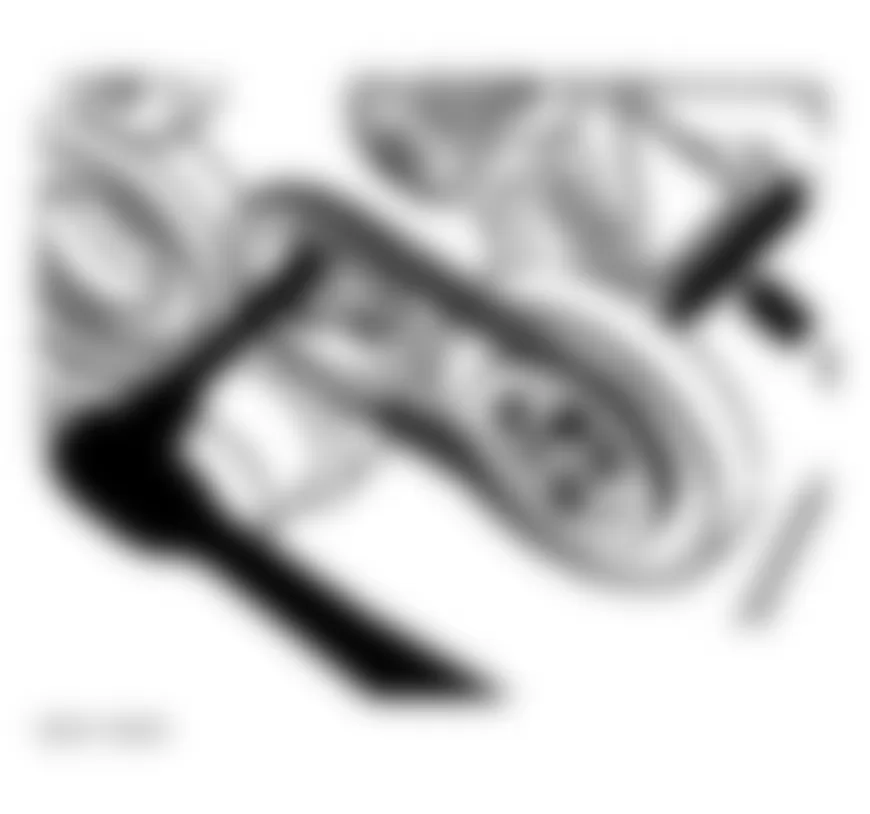
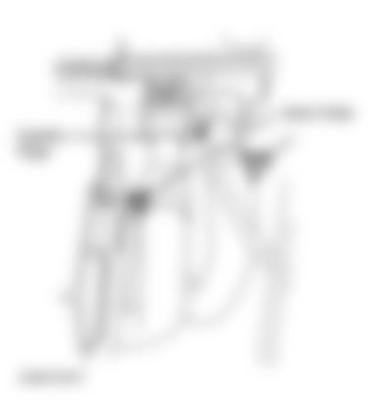
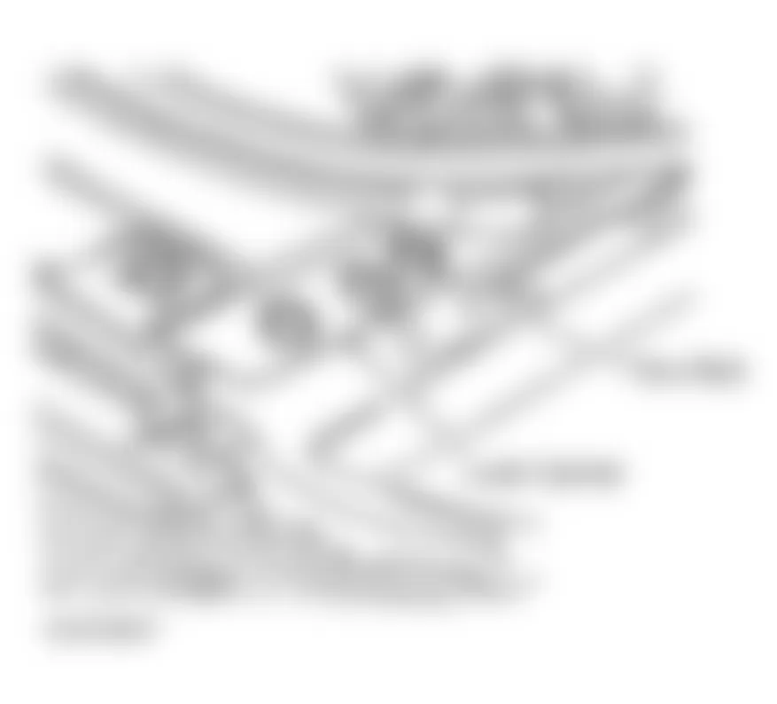
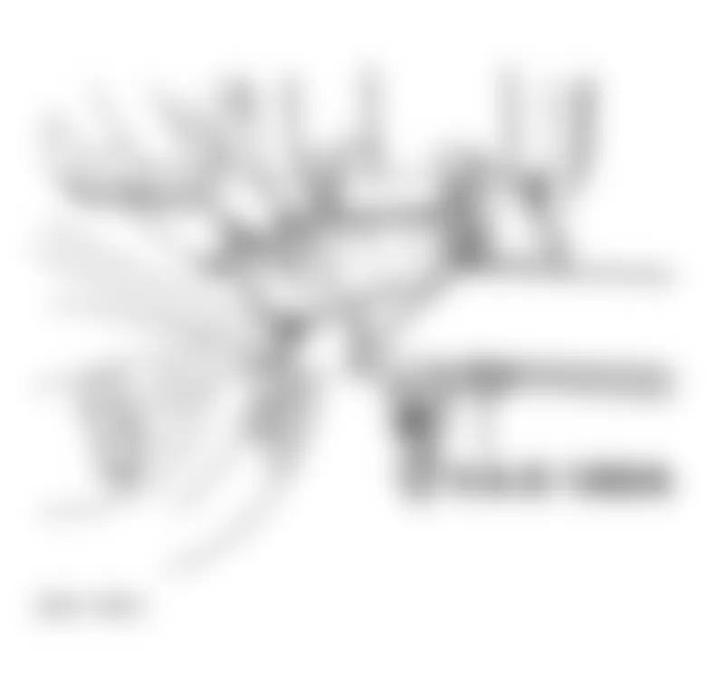
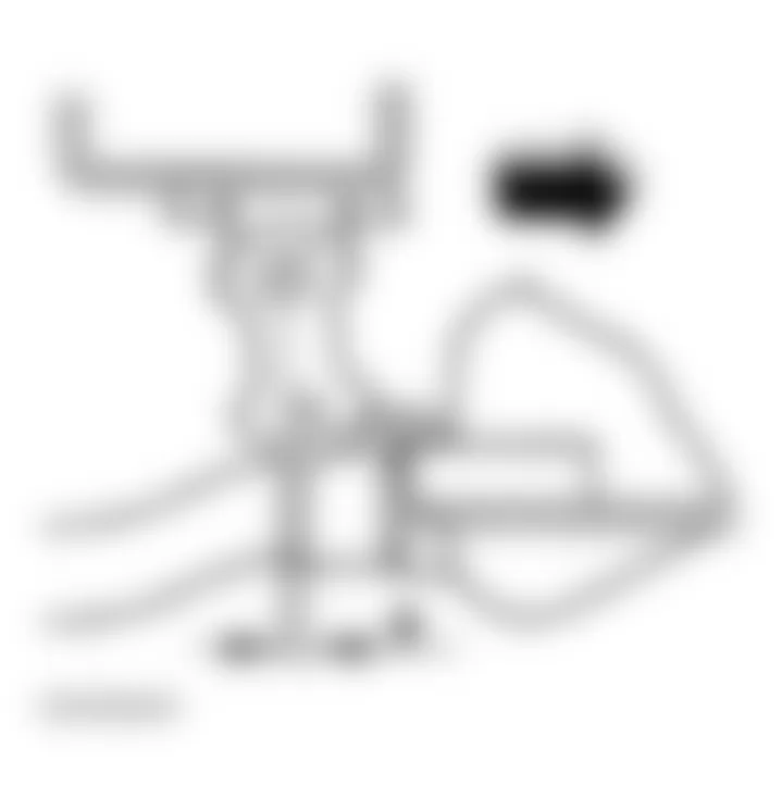
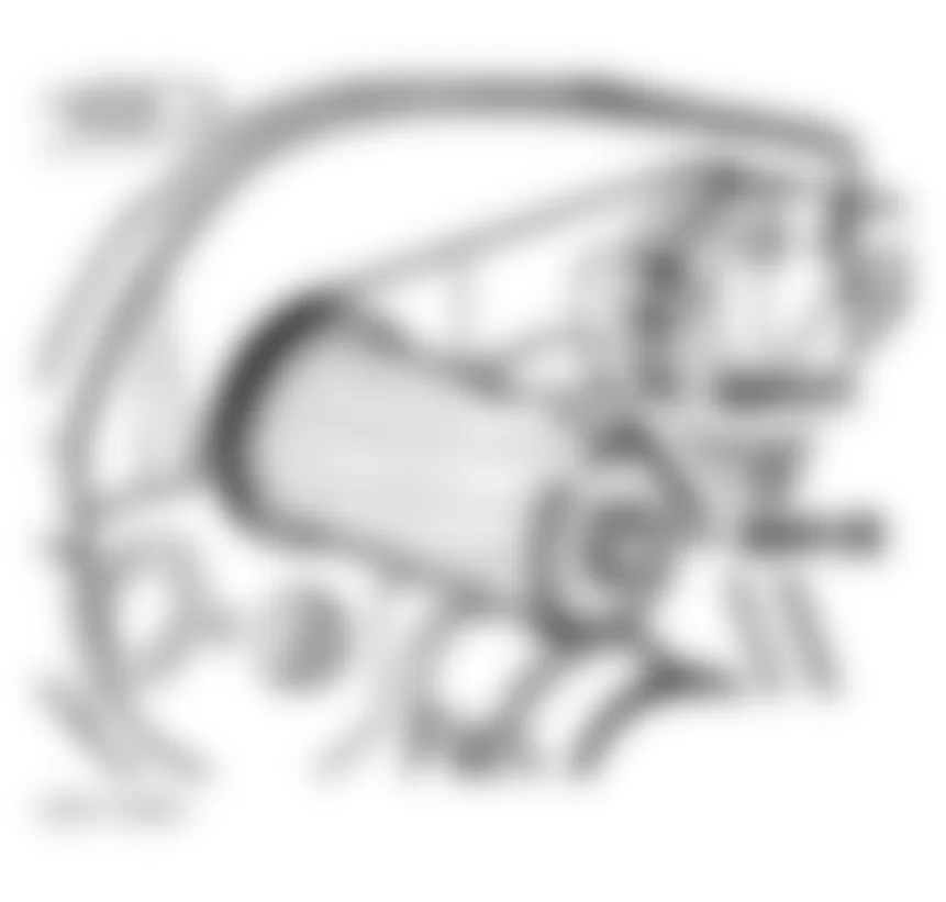
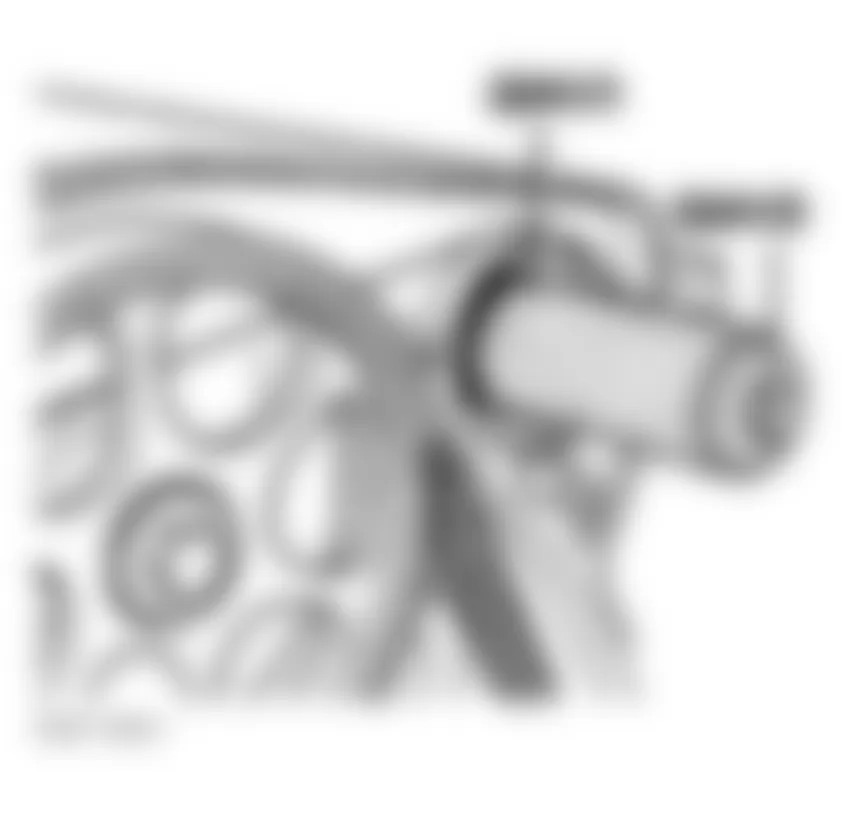
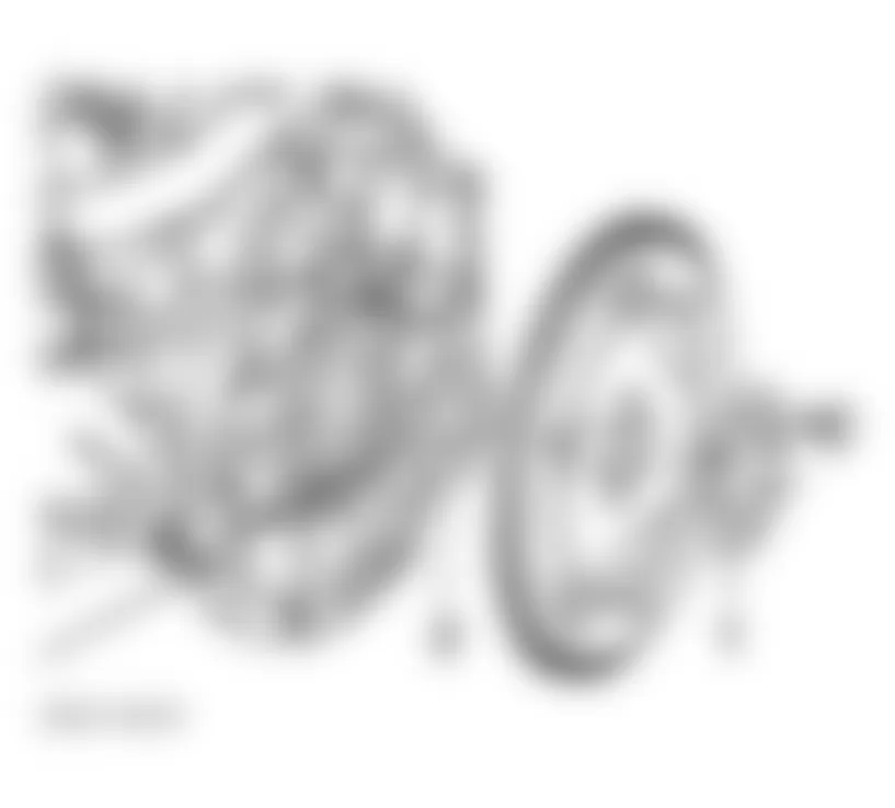
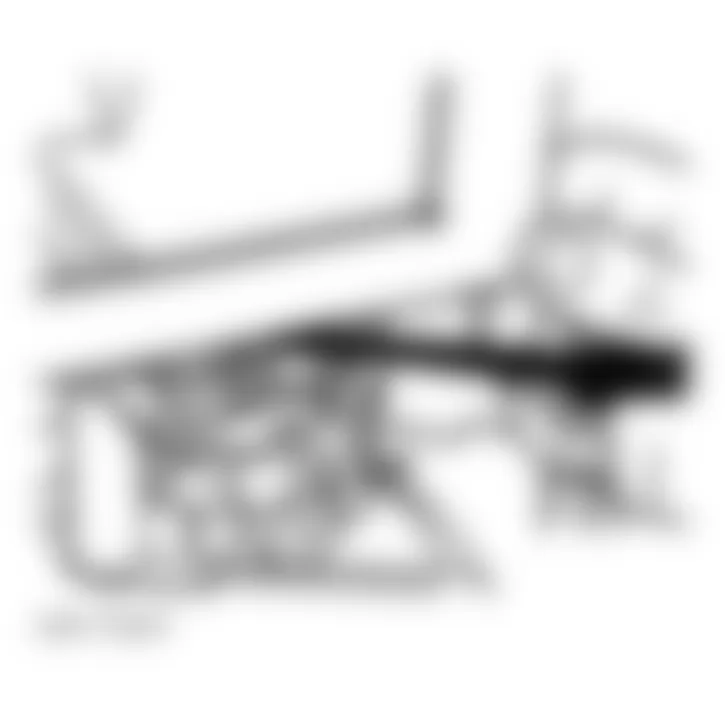
- Remove accessory drive belts. Drain engine coolant. See DRAINING COOLING SYSTEM. Remove generator. Unbolt power steering pump assembly and set aside with hoses attached. See Fig. 4.
- Label and remove coolant hoses from water pump. Remove water pump pulley. See Fig. 3.
- Remove timing belt lower cover (ensure all bolts are removed). Remove mounting bolts and remove water pump assembly. To install, reverse removal procedure. Tighten bolts to specification. See TORQUE SPECIFICATIONS. Fill and bleed cooling system. See COOLING SYSTEM BLEEDING.
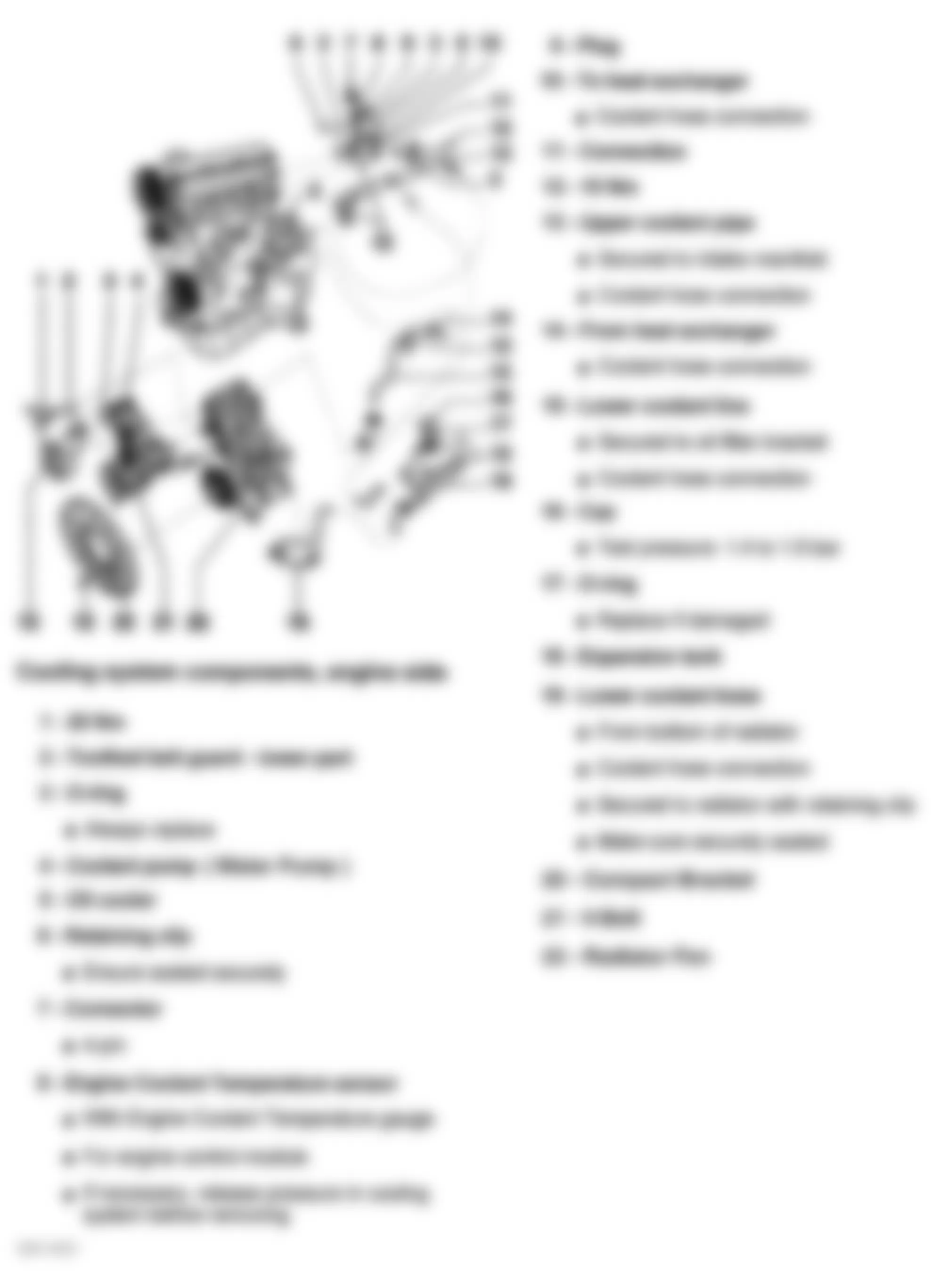
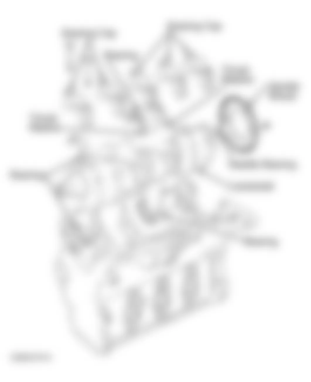
Fig. 4: Audi A4 1998 - Component Locations - Identifying Cooling System Components
Audi A4 1998 - PROGRAMMING
NOTE: When battery is disconnected, vehicle computer and memory systems may lose memory data. Driveability problems may exist until computer systems have completed a relearn cycle.
After any repair which required that the battery be disconnected, the following should be performed. - owners manual for additional information.
- Ensure ignition switch is in OFF position. Reconnect battery positive cable first then connect the negative ground strap.
- After connecting battery, enter anti-theft code for radio (if equipped).
- Fully close all power windows, operate each window door switch in up position for at least one second (windows closed) to activate "one touch" opening/closing function (if equipped).
- Set clock to correct time.
Audi A4 1998 - ADJUSTMENTS ACCELERATOR PEDAL
- Remove clip for accelerator pedal cable on throttle body. Depress accelerator pedal to Wide Open Throttle (WOT) position.
- On manual transmission vehicles, pull sleeve on accelerator pedal cable off curved washer on throttle body until throttle body has opened completely. On automatic transmission vehicles, pull accelerator pedal cable sleeve back to WOT position far enough so throttle has opened completely and kickdown switch audibly clicks.
- On all vehicles, hold pedal tight in position. Install securing clip for accelerator pedal cable sleeve. Release accelerator pedal. Adjustment is complete. After adjustment, verify WOT position and check idle speed.
Audi A4 1998 - VALVE CLEARANCE
Engine is equipped with non-adjustable, non-serviceable hydraulic valve adjusters. Irregular valve adjuster noise during cranking is normal. If valve adjuster(s) are noisy under any other condition inspect valve adjusters. See HYDRAULIC VALVE ADJUSTERS under REMOVAL & INSTALLATION.
Audi A4 1998 - TROUBLESHOOTING
To trouble shoot mechanical engine components, see appropriate table in TROUBLE SHOOTING article in GENERAL INFORMATION.
Audi A4 1998 - REMOVAL & INSTALLATION
CAUTION: Radio/cassette or radio/CD player is equipped with an anti-theft protection circuit. Whenever battery is disconnected, radio will go into anti-theft mode. When battery is reconnected, radio will display CODE, and will be inoperative until proper code number is entered. Obtain security code before disconnecting battery.
NOTE: When battery is disconnected, vehicle computer and memory systems may lose memory data. Driveability problems may exist until computer systems have completed a relearn cycle.
NOTE: For reassembly reference, label all electrical connectors, vacuum hoses and fuel lines before removal. Place mating marks on other major assemblies before removal.
Audi A4 1998 - ACCESSORY DRIVE BELTS
CAUTION: If reusing old serpentine or other accessory drive belt(s), mark the running direction of belt with crayon or marker. Reinstalling a used belt in reversed direction could damage the belt, and cause component(s) or engine damage.
NOTE: Serpentine belt may also be referred to as ribbed belt or V-belt.
For help in identifying accessory drive belt(s) routing and component locations, refer to illustration. See Fig. 7.
Audi A4 1998 - Removal & Installation (A/C Belt)
- Raise vehicle, remove lower engine shield (noise insulator). Move lock carrier to service position. See LOCK CARRIER. Loosen 2 mounting bolts at A/C belt tensioner, release tension from belt.
- Remove belt. To install, reverse removal procedure. Ensure pulleys are free of debris. Using a torque wrench tension belt to 18 ft. lbs. (25 N.m). Tighten mounting bolts to 15 ft. lbs. (20 N.m).
- Start engine and check belt running condition.
Audi A4 1998 - Removal & Installation (Serpentine Belt)
- Raise vehicle, remove lower engine shield (noise insulator). See Fig. 2.
- Move lock carrier to service position. See LOCK CARRIER.
- Install wrench on ear of serpentine belt tensioner, move clockwise to remove tension off belt. See Fig. 5. Tensioner can be locked into released position by inserting a properly sized Hex wrench into hole in tensioner. See Fig. 6.
- Remove belt. To install, reverse removal procedure. Ensure pulleys are free of debris. Belt is automatically tensioned.
- Start engine and check belt running condition.
Fig. 5: Audi A4 1998 - Component Locations - Removing/Installing Alternator Belt (A4)
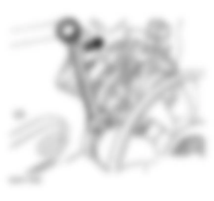
Fig. 6: Audi A4 1998 - Component Locations - Securing Tensioner
Audi A4 1998 - Removal & Installation (Water Pump Belt)
- Raise vehicle, remove lower engine shield (noise insulator). See Fig. 2.
- Move lock carrier to service position. See LOCK CARRIER. Release tension off serpentine belt. See REMOVAL & INSTALLATION (SERPENTINE BELT).
- Remove viscous fan with pulley from its bearing. See VISCOUS FAN (ENGINE COOLING).
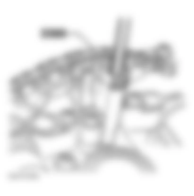
- Using a drift punch to lock up the P/S pump pulley (1), remove fasteners from belt pulley for water pump. See Fig. 8. Remove belt.
- To install, reverse removal procedure. Ensure pulleys are free of debris. Place belt around P/S pulley then between the 2 halves of the water pump pulley. Slowly go around as you tighten the fasteners (pulleys are also turning). The belt should walk its way out in the pulley groove. Using a torque wrench, tighten pulley bolts to 15 ft. lbs. (20 N.m).
- Tension the serpentine belt. DO NOT install fan at this time. Start engine only for a moment to seat the belt and check belt running condition. Turn ignition switch to OFF position. Recheck torque on water pump pulley bolts.
Fig. 7: Audi A4 1998 - Component Locations - Identifying Accessory Drive Belts & Components

Fig. 8: Audi A4 1998 - Component Locations - Removing Water Pump Pulley & Belt
Audi A4 1998 - DRAINING COOLING SYSTEM
WARNING: The cooling system is pressurized when the engine is warm. When opening the expansion tank, wear gloves and other appropriate protection, cover the cap with a cloth and open carefully to relieve system pressure slowly.
NOTE: Drain coolant into clean container if coolant is in good condition and is going to be reused.
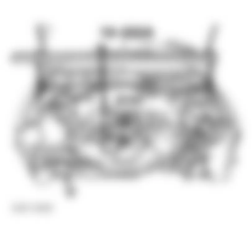
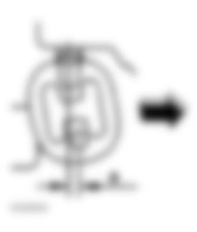
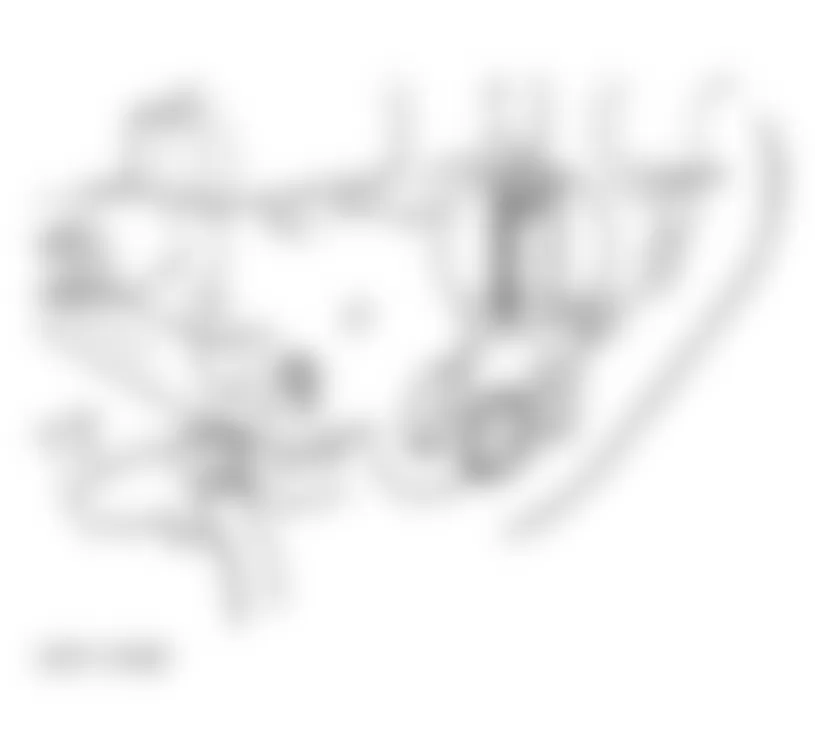
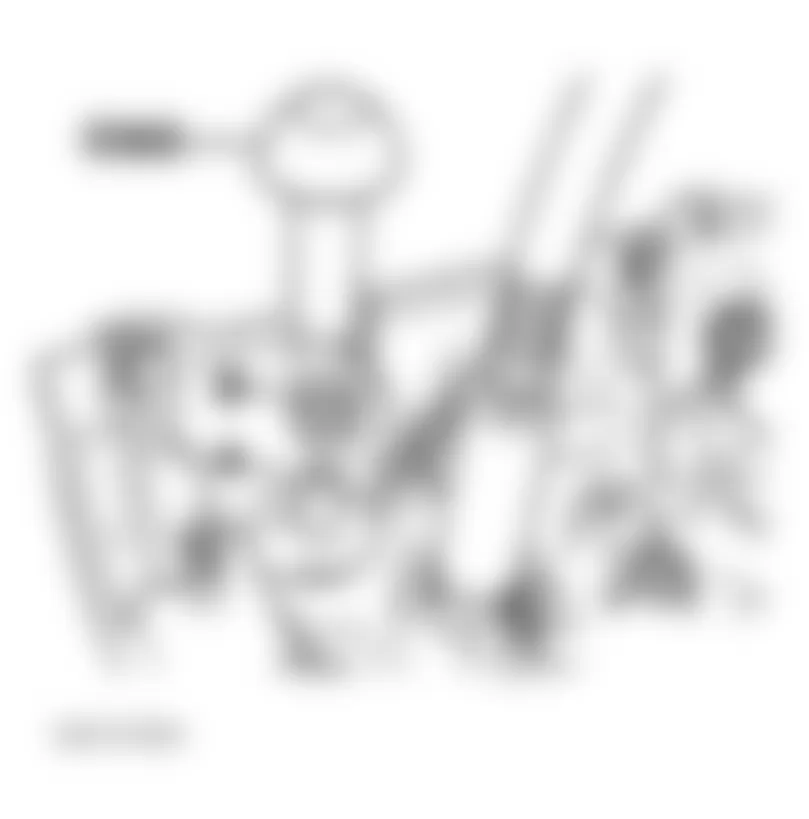
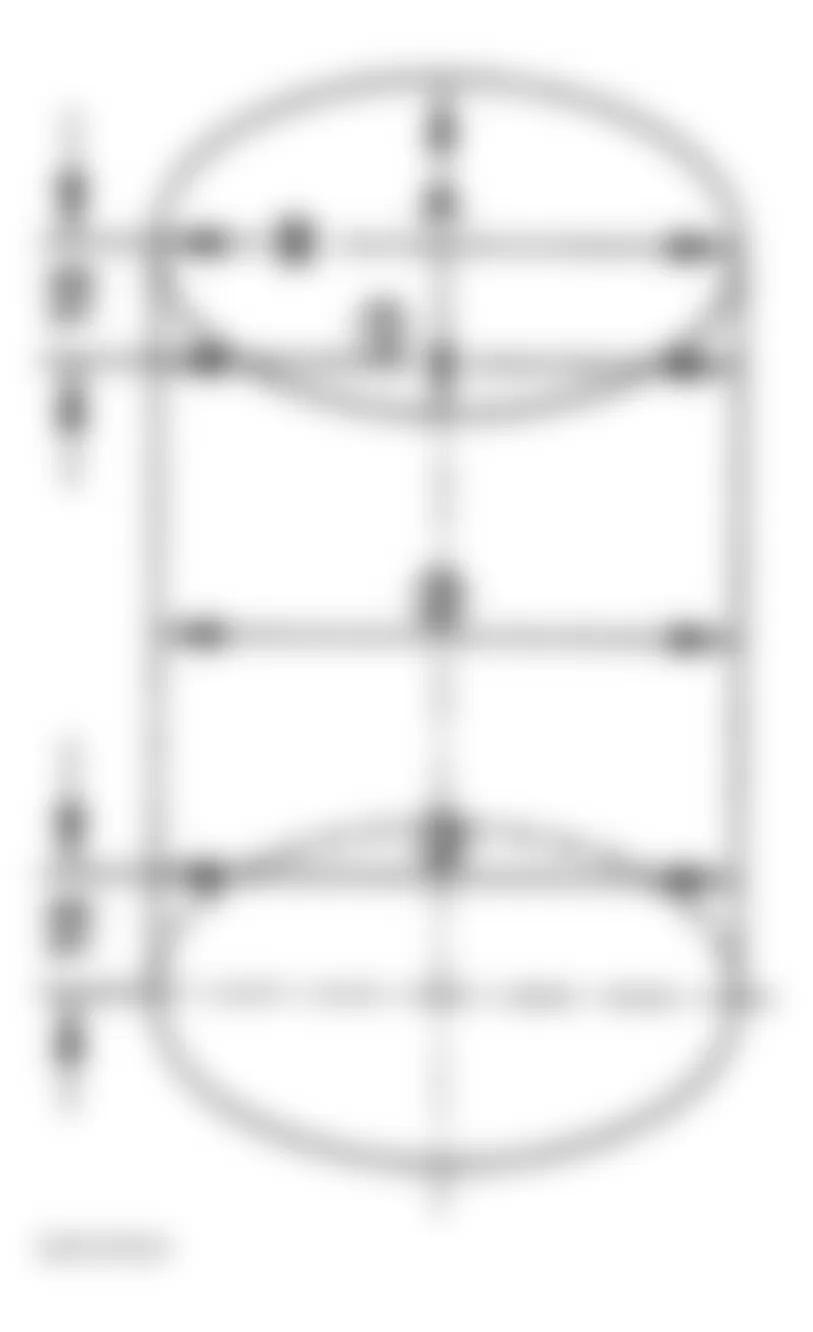
Open cap on engine coolant expansion tank. Remove lower engine shield (noise insulator). Remove lower radiator hose (1). Drain coolant from radiator and hose. Remove drain plug (2) from coolant pump and allow coolant to drain from block. See Fig. 9 and Fig. 10 . To fill cooling system, see COOLING SYSTEM BLEEDING.
Fig. 9: Audi A4 1998 - Component Locations - Draining Engine Coolant
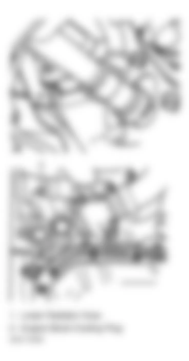
Fig. 10: Audi A4 1998 - Component Locations - Coolant Hose Connection & Routing Diagram
Audi A4 1998 - COOLING SYSTEM BLEEDING
- Ensure coolant pump drain plug with NEW O-ring and all hoses are secure. See Fig. 9.
- Install fill adaptor to coolant expansion tank. See Fig. 11 and Fig. 12 . If special tools are not used, loosen expansion tank and raise about 4 INCHES. Keep in this position while filling. Expose vent hole on heater pipe at firewall connection by pulling back heater hose. See Fig. 13. Fill cooling system through expansion tank until coolant comes out of vent hole. Tighten heater hose and bleed screw.
- Fill expansion tank to proper level. Install expansion tank cap. Put heater controls in hot position. Start engine and raise engine speed to 2000 RPM for about 3 minutes. Ensure cooling fan operates. Return engine to idle. Check coolant level in expansion tank. Fill as necessary. With engine at normal operating temperature, coolant should be at the Max mark indicated on expansion tank. Once engine has completely cooled, coolant should be at the low mark. Add coolant as necessary.
Fig. 13: Audi A4 1998 - Component Locations - Locating Heater Hose Vent Hole
Audi A4 1998 - FUEL PRESSURE RELEASE
Remove fuel pump relay from fuse/relay block under left side of instrument panel. Start engine. Allow engine to run until it stops. Turn ignition off. Disconnect negative battery cable. Install fuel pump relay. Slight pressure may remain in system. Before disconnecting any fuel system line, cover connector with a clean shop towel.
Audi A4 1998 - LOCK CARRIER
NOTE: The following procedures are for moving lock carrier into service position. This will allow access to front of engine.
Audi A4 1998 - A4
- Remove complete front bumper assembly. Remove engine undercover. Remove air intake duct from air filter housing. Disconnect all necessary electrical connectors from front of vehicle.
- Install Lock Carrier Support Tool (3369) through lock carrier to chassis. See Fig. 14 and Fig. 15 . Remove lock carrier support bolts securing lock carrier to vehicle. Slide lock carrier forward onto support tool. This will allow servicing of front engine components.
- To complete installation, reverse removal procedure. Ensure lock carrier Torx bolts are installed in correct position. See Fig. 16.
Fig. 14: Audi A4 1998 - Component Locations - Exploded View Of Lock Carrier Assembly (A4)
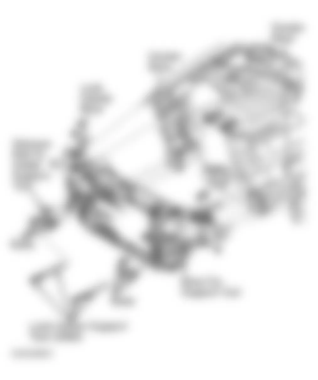
Fig. 15: Audi A4 1998 - Component Locations - Positioning Lock Carrier Support Tool (3369) For A4
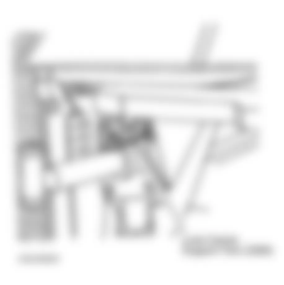
Fig. 16: Audi A4 1998 - Component Locations - Positioning Lock Carrier Assembly Torx Bolts (A4)
Audi A4 1998 - Passat - First Design
- Remove noise insulation. See Fig. 2. Disconnect intake air ducting located near radiator support. Disconnect headlight and turn signal electrical connectors. Disconnect harness connectors at horns. See Fig. 23.
- Disconnect coolant fan thermal switch. Disconnect power steering cooling coil. Remove front bumper.
- Unbolt air guide between lock carrier and air filter on lock carrier. See Fig. 17.
- Unscrew bolt (No. 3) and replace with Support Tool (Part No. 3369) onto right and left-hand longitudinal member. See Fig. 18.
- Unscrew bolts (No. 2 and 4) and pull lock carrier in area of Support Tool (3369) forward (moving to service position). To install, reverse removal procedure.
Fig. 17: Audi A4 1998 - Component Locations - Identifying Lock Carrier Components (First Design)
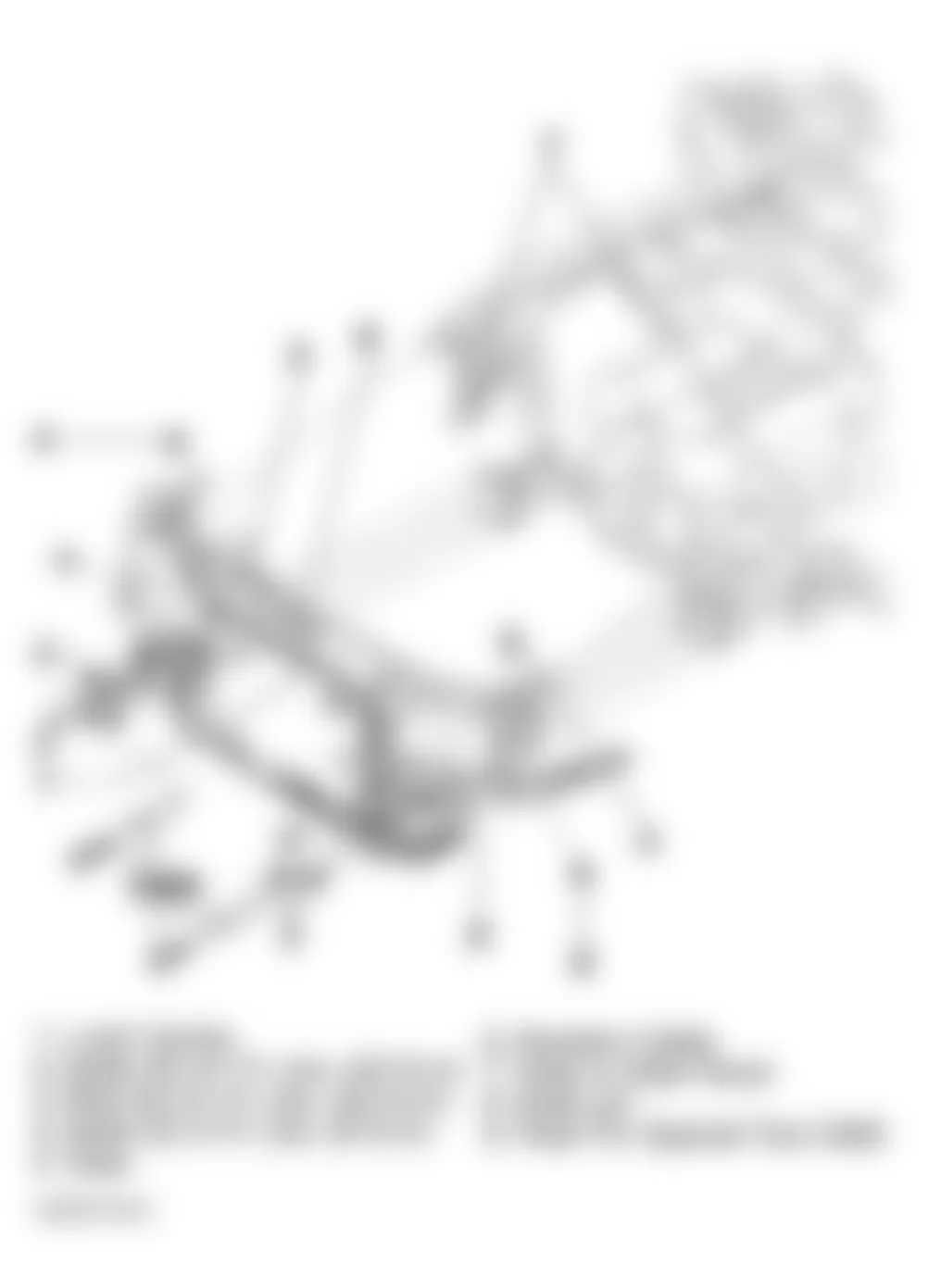
Fig. 18: Audi A4 1998 - Component Locations - Identifying Support Tool (3369)
Audi A4 1998 - Passat - Second Design
- Remove noise insulation. See Fig. 2. Disconnect intake air ducting located near radiator support. Disconnect headlight and turn signal electrical connectors.
- Disconnect harness connectors at horns. See Fig. 23. Disconnect coolant fan thermal switch. Disconnect power steering cooling coil. Remove front bumper.
- Unbolt air guide between lock carrier and air filter at lock carrier. See Fig. 19. Remove bolts (No. 5) and replace with Guide Rods (3411) to right and left long member.
- Remove bolts (No. 2 and 3). Lock carrier can be pulled forward approximately 4" (10 cm) on Guide Rods (3411). See Fig. 20 and Fig. 21 .
- To install, reverse removal procedure.
Fig. 19: Audi A4 1998 - Component Locations - Identifying Lock Carrier Components (Second Design)
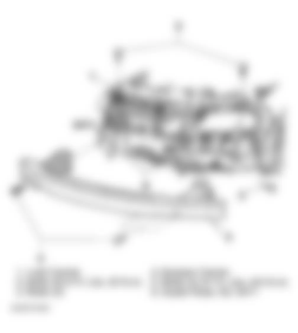
Fig. 20: Audi A4 1998 - Component Locations - Identifying Guide Rods (3411)

Fig. 21: Audi A4 1998 - Component Locations - Identifying Installed Location Of Guide Rods (3411)
Audi A4 1998 - ENGINE
WARNING: ALWAYS release fuel pressure before disconnecting fuel injection related component. DO NOT allow fuel to contact engine or electrical components.
NOTE: Obtain radio code before disconnecting battery. Remove engine, without transmission, through front of engine compartment.
NOTE: For help in identifying components and component locations, refer to illustrations. See Fig. 22-Fig. 41 .
Audi A4 1998 - Removal
- Release fuel pressure. See FUEL PRESSURE RELEASE. Turn ignition on, operate windshield wipers till wiper arms are in the vertical position (pointing up) turn off ignition. Remove battery. Remove lower engine shield (noise insulator). See Fig. 2. Drain engine oil. Drain coolant, see DRAINING COOLING SYSTEM.
WARNING: The cooling system is pressurized when the engine is warm. When opening the expansion tank, wear gloves and other appropriate protection, cover the cap with a cloth and open carefully to relieve system pressure slowly. - Remove cover for fuel injectors. Disconnect fuel supply and return lines at fuel rail. See Fig. 22. Disconnect intake air ducting located near radiator support. Disconnect headlight and turn signal electrical connectors.
- Disconnect harness connectors at horns. See Fig. 23. Disconnect coolant fan thermal switch. Disconnect power steering cooling coil, located at lower left of radiator. Let cooling coil hang free. See Fig. 24 . Remove front bumper. See LOCK CARRIER.
- Remove Motronic Engine Control Module (E-Box) cover and disconnect harness connectors. See Fig. 25 and Fig. 26. Disconnect Kickdown switch harness connector. See Fig. 27. Disconnect Vehicle Speed Sensor (VSS). On Manual Transmission (M/T) disconnect harness connector from transmission (backup lights). Disconnect Anti-Lock Brake System (ABS) harness connectors. See
Fig. 28. - Disconnect Oxygen Sensor harness connect, remove fasteners and ground wires and set harness bracket aside. See Fig. 29 and Fig. 30.
- Disconnect power steering line clamps on frame and radiator brace. See Fig. 24. Disconnect turbocharger, air intake and throttle valve control module ducts. Disconnect chassis grounds and all electrical connectors, disconnect cables and hoses that would interfere with engine removal.
NOTE: DO NOT open the air conditioning refrigerant circuit. Disconnect green electrical connector to A/C compressor. See Fig. 31. Disconnect A/C refrigerant line brackets at support points only. After A/C compressor is removed from bracket, support with wire and set A/C compressor carefully aside, avoid damage from bending or kinking refrigerant lines. - Remove left and right side air ducts (4). Remove condenser mounting bolts (1) and (2). Disconnect harness connector (3) for A/C pressure switch. See Fig. 33. Pull condenser up out of its bracket, rotate it to side and use wire to secure it on or near right front wheel.
- Disconnect front exhaust pipe from exhaust manifold. Disconnect front exhaust pipe from catalytic converter. Remove front catalytic converter from turbocharger. Disconnect harness connectors from around air cleaner box. Remove air cleaner box. See Fig. 32. Disconnect accelerator pedal cable from the throttle valve control module. DO NOT remove locking clip on accelerator pedal cable. See Fig. 35. Disconnect Leak Detection Pump (LDP) vacuum lines. See Fig. 36.
- Disconnect all coolant and heater hoses. Remove coolant system expansion reservoir and set aside. See Fig. 34. Remove starter motor. Remove bracket from ATF line from transmission.
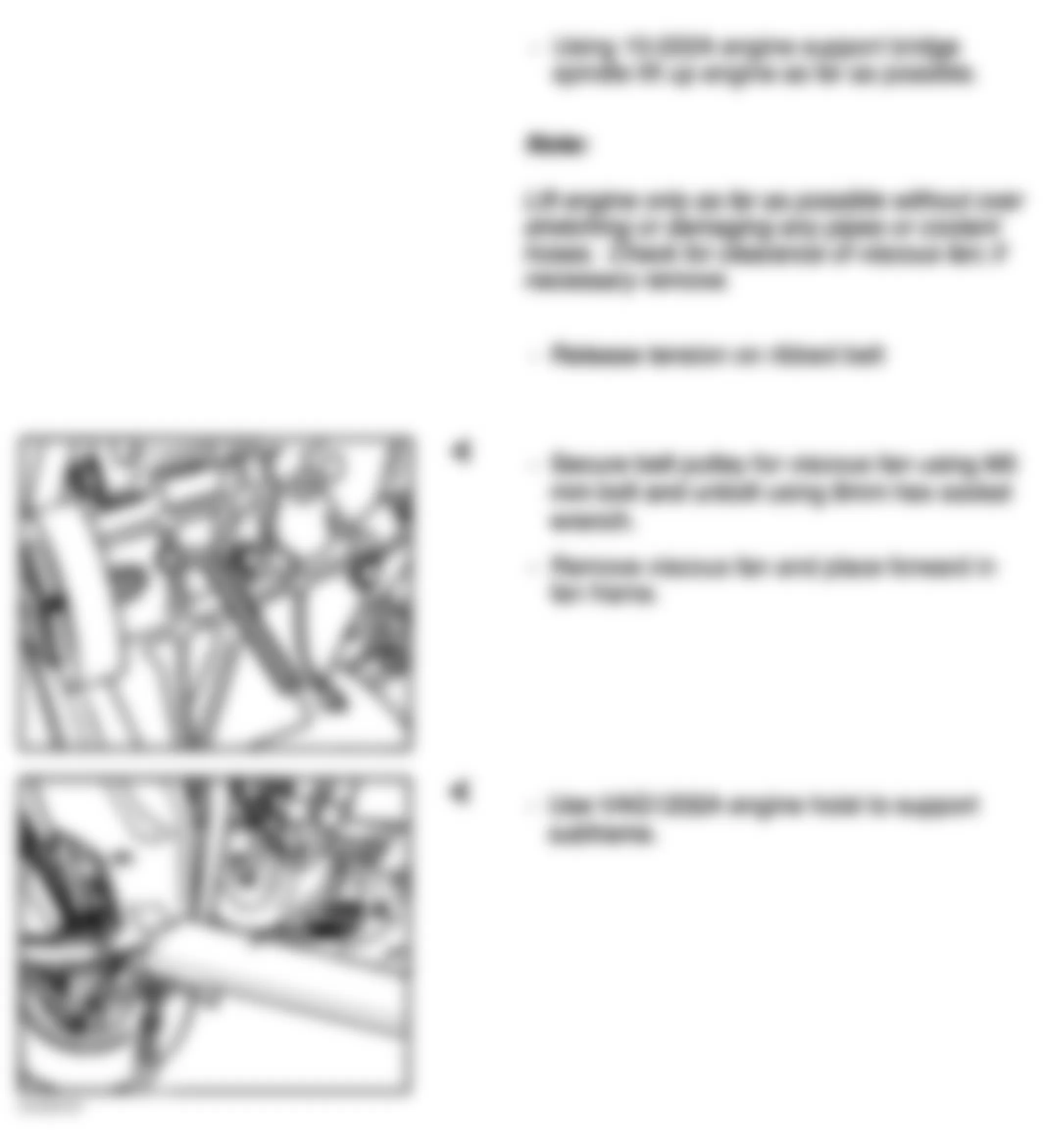
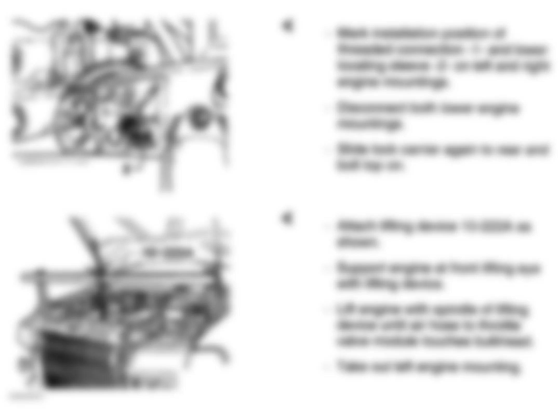
- Remove upper engine-to-transmission bolts. Mark positions of left and right engine mount locating sleeves from bottom. See Fig. 37. Remove lower left and right engine mount nuts. If equipped with automatic transmission, raise vehicle, remove 3 torque converter bolts accessed through starter pinion hole at bell housing. See Fig. 38. Lift engine and transmission slightly using (VAG 1202 A) workshop crane to allow lower engine/transmission connecting bolts to be removed. See Fig. 39. Remove lower engine/transmission connecting bolts.
- Install Engine Support Bracket (10-222A) and Hooks (10-222A/2) to engine. Install Transmission Support (3147) to transmission bellhousing bolt hole. See Fig. 40 and Fig. 41 . Carefully raise engine out of vehicle.
CAUTION: DO NOT allow torque converter to fall out of bell housing.
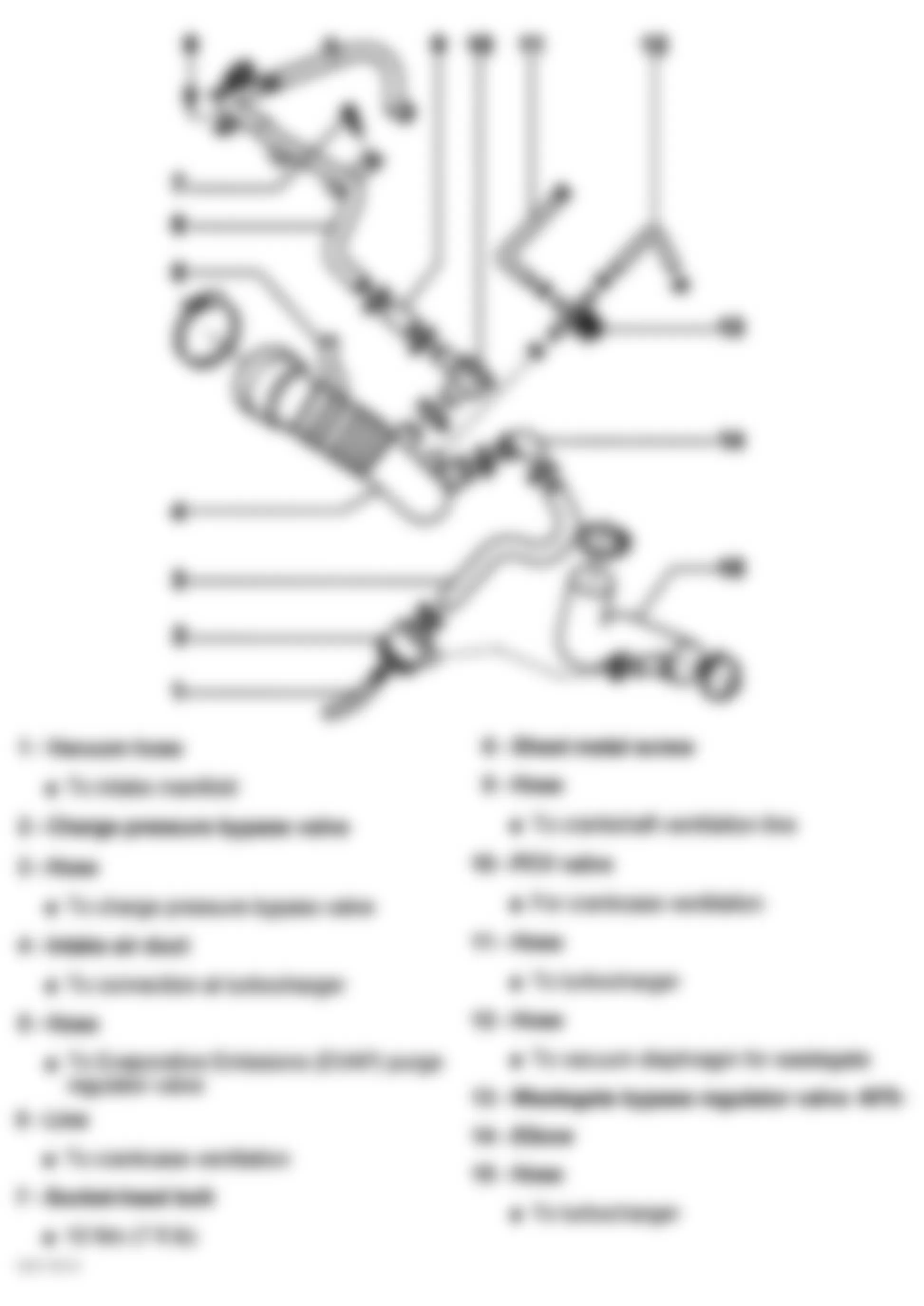
Fig. 22: Audi A4 1998 - Component Locations - Identifying Fuel Lines & Brake Booster Vacuum Hose
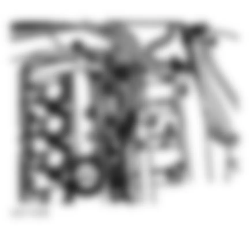
Fig. 23: Audi A4 1998 - Component Locations - Identifying Horns Harness connectors
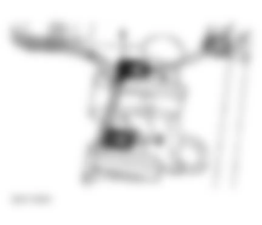
Fig. 24: Audi A4 1998 - Component Locations - Identifying Power Steering Cooler Line Mounting Points

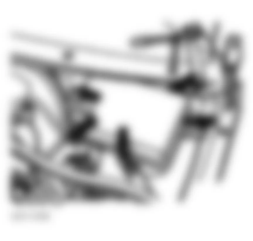
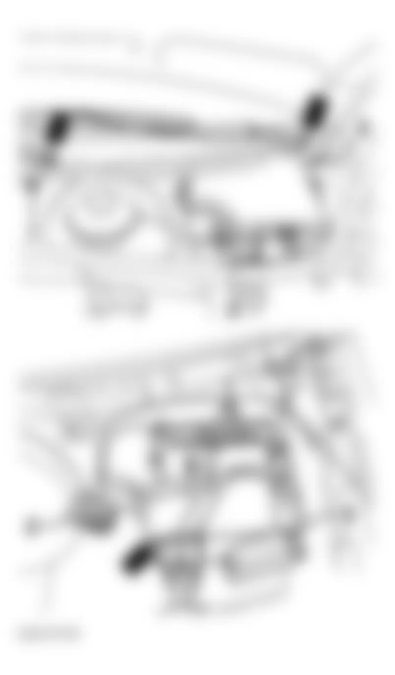
Fig. 27: Audi A4 1998 - Component Locations - Identifying Kickdown Switch Harness Connector
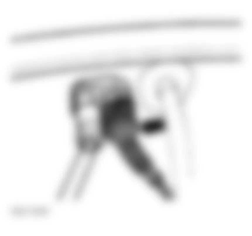
Fig. 28: Audi A4 1998 - Component Locations - Identifying Anti-Lock Brake System Harness Connectors

Fig. 29: Audi A4 1998 - Component Locations - Identifying Oxygen Sensor Harness Connector
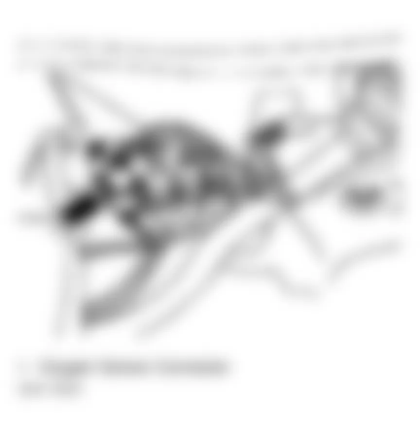
Fig. 30: Audi A4 1998 - Component Locations - Identifying Harness Connector Bracket
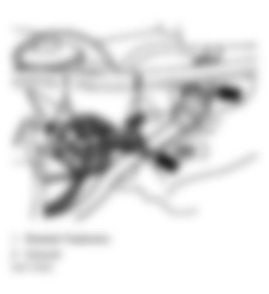
Fig. 31: Audi A4 1998 - Component Locations - Identifying A/C Compressor Harness Connector (Green)
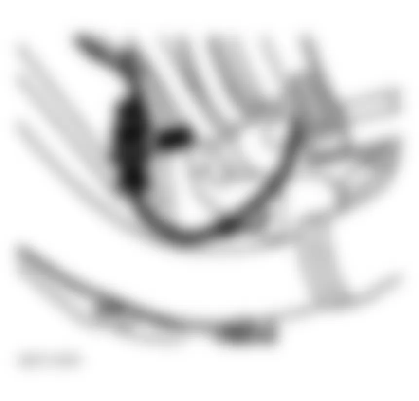
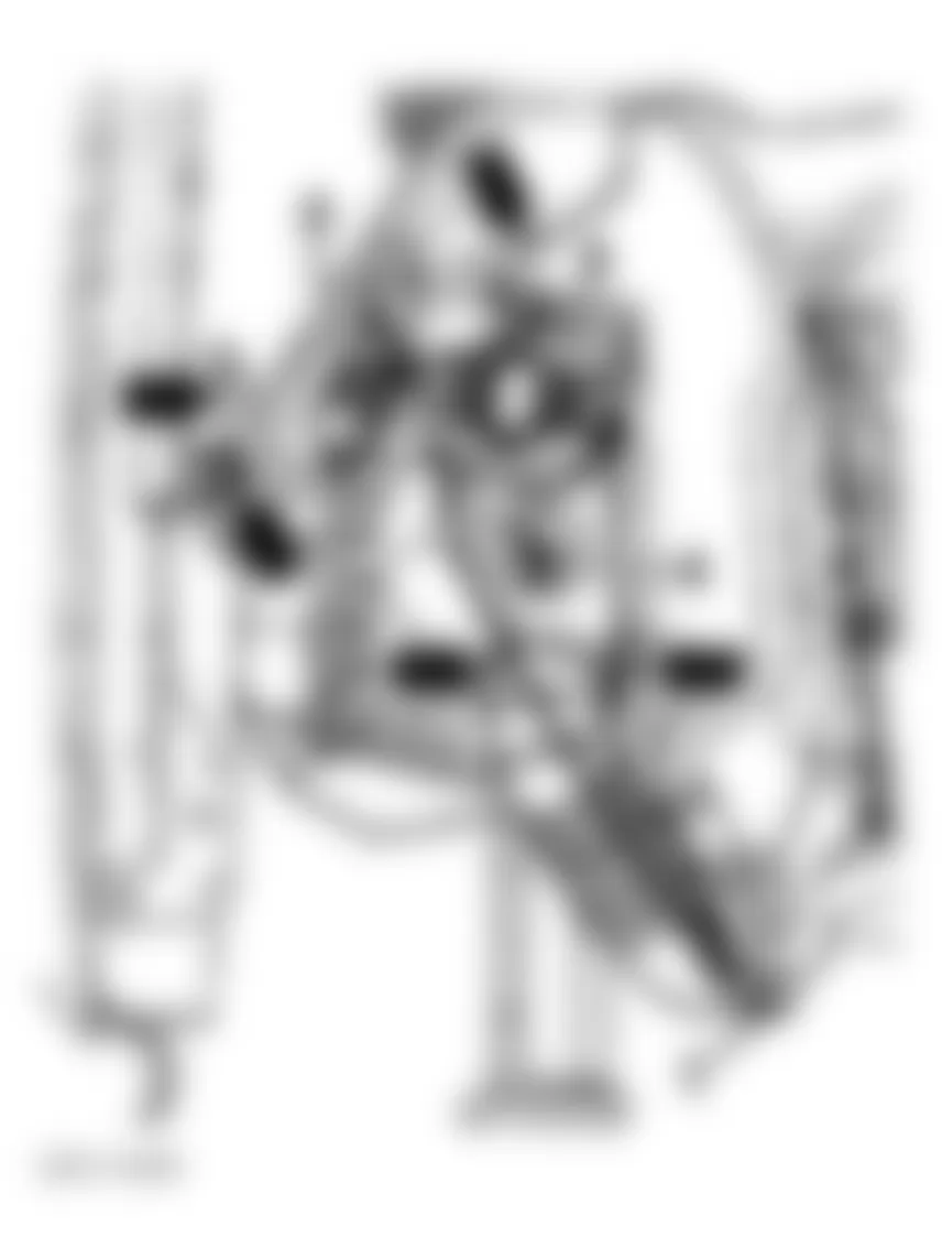
Fig. 33: Audi A4 1998 - Component Locations - Identifying Location Of A/C Pressure Switch
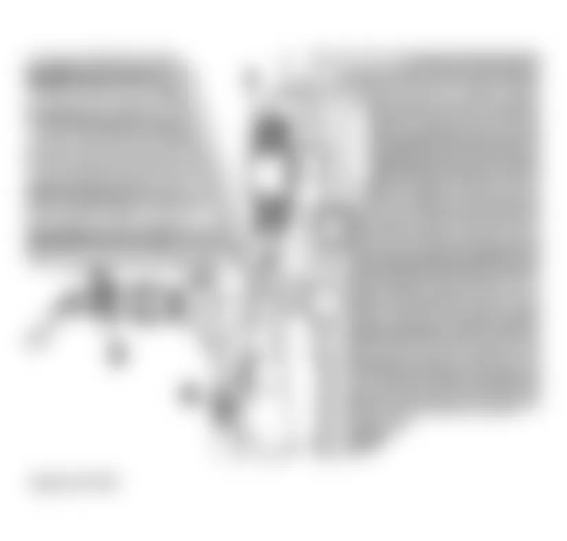
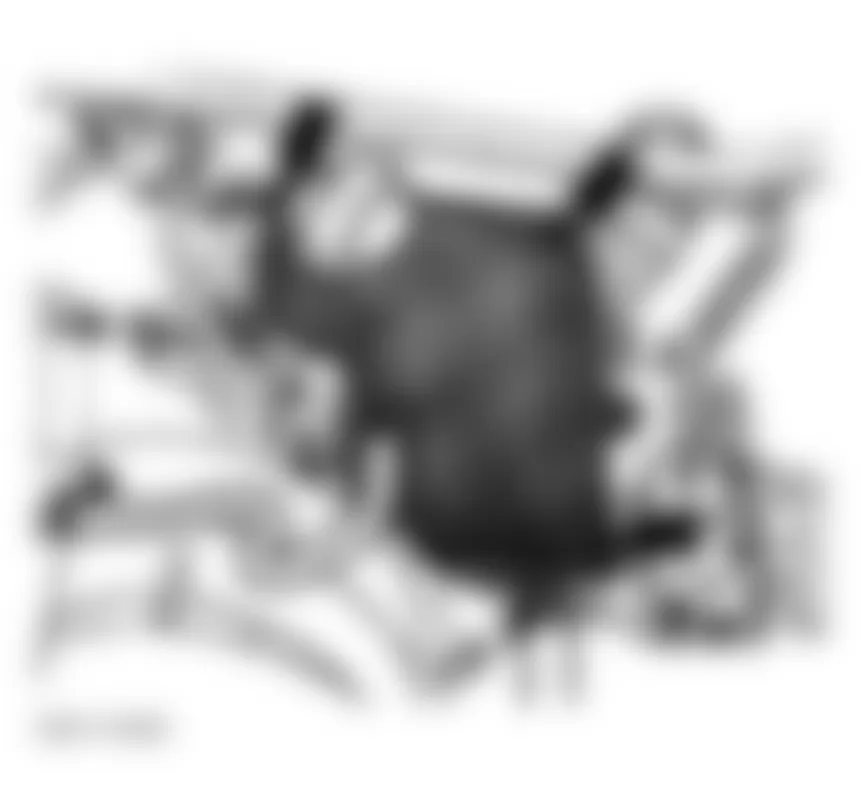
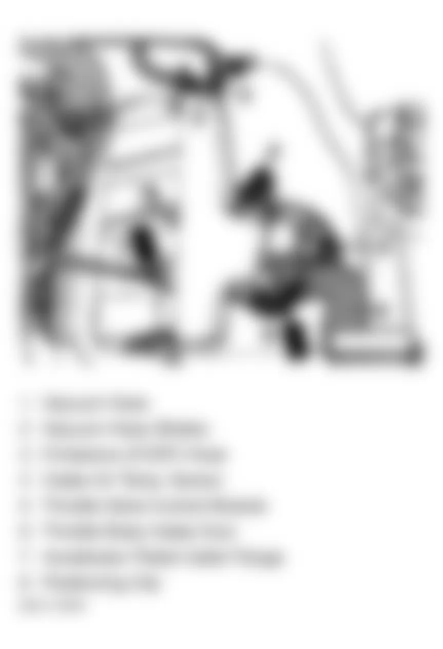
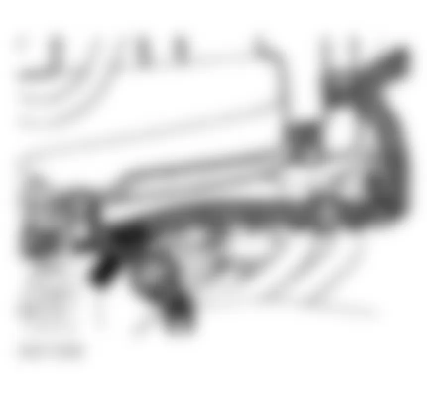
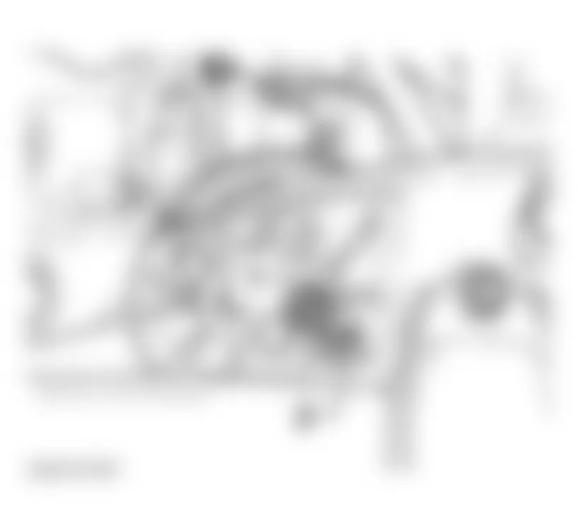
Fig. 38: Audi A4 1998 - Component Locations - Identifying Access To Torque Converter Bolts
Audi A4 1998 - Installation
- To install, reverse removal procedure. Engine alignment adjustment is necessary whenever engine is removed or mounts are loosened. To adjust, loosen through-bolt on engine mount. Loosen transmission mount bolts. Loosen front engine mount and bracket.
- Lightly rock engine and transaxle to shift as necessary. Evenly tighten mount bolts in reverse order of loosening. Align exhaust so components are free of stress. For Audi A4, see ALIGNING EXHAUST SYSTEM: AUDI A4 ENGINE CODES AEB & ATW. For Passat, see ALIGNING EXHAUST SYSTEM: PASSAT ENGINE CODES AEB & ATW. Tighten all bolts and nuts to specification. See TORQUE SPECIFICATIONS.
- Adjust accelerator pedal. See ACCELERATOR PEDAL under ADJUSTMENTS. Verify engine fluid levels are filled to proper levels. Adjust clutch pedal (if equipped).
Audi A4 1998 - Aligning Exhaust System: Audi A4 (Engine Codes AEB & ATW)
CAUTION: Do not re-use any fasteners that are worn or deformed in normal use. Some fasteners are designed to be used only once, and are unreliable and may fail if used a second time. This includes, but is not limited to, nuts, bolts, washers, circlips and cotter pins. Replace these fasteners with new parts where it is deemed necessary by inspection. Always replace gaskets and self-locking nuts. The exhaust flexpipe must not be bent more than 10 degrees, otherwise it may be damaged.
NOTE: After exhaust system repairs or reinstallation, make sure exhaust system is not under stress and that it has sufficient clearance from the bodywork. If necessary, loosen double clamps and align muffler and exhaust pipe so that sufficient clearance is maintained to the bodywork and the support rings are evenly loaded.
Audi A4 1998 - Front Wheel Drive Vehicles
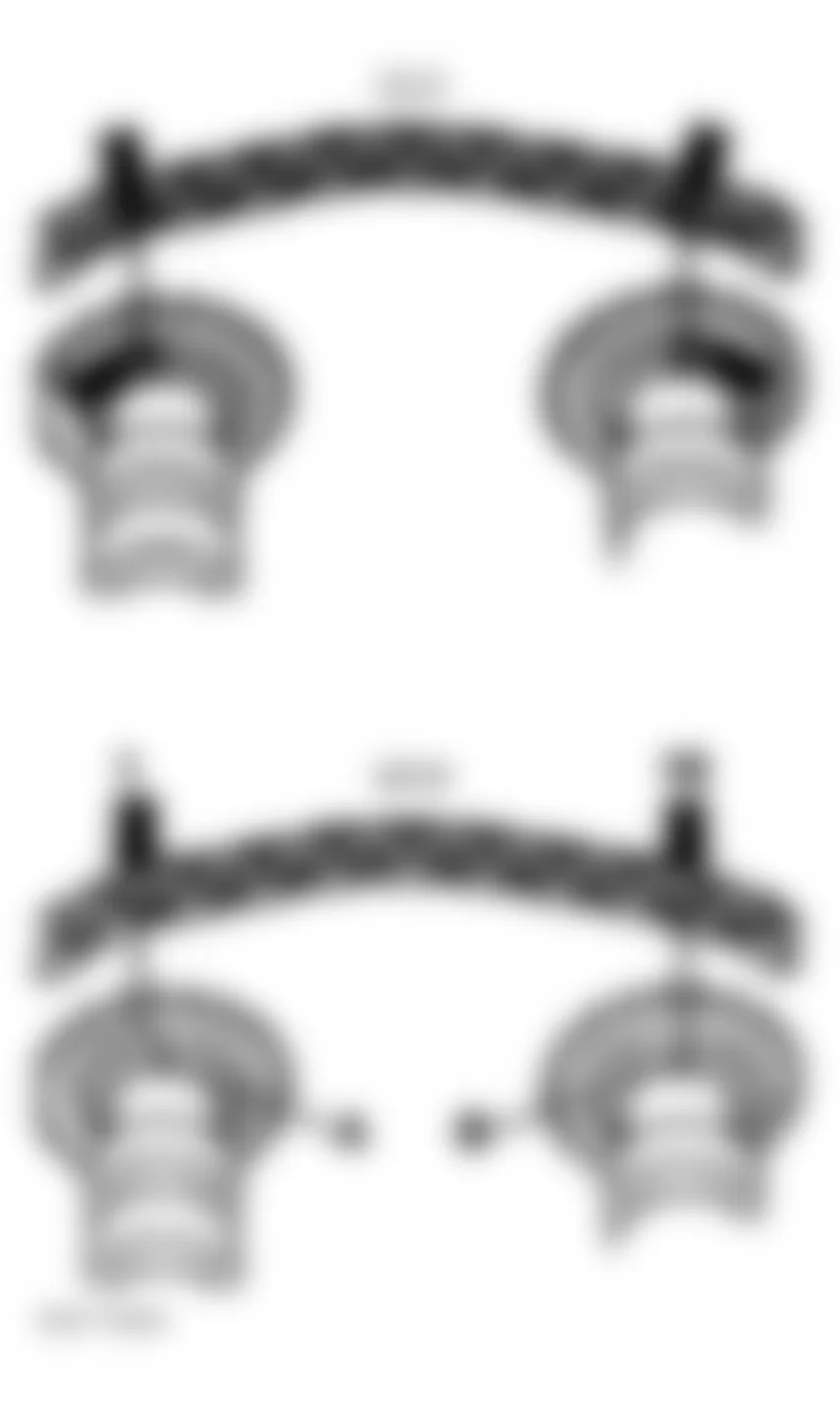
- Align exhaust system when cold. Double clamp is located at the front of front muffler pipe. Remove double clamp bolts. Push exhaust system forward (arrow) until tension on rear mount equals dimension a in Fig. 42. Dimension a is 7-9 mm (0.275-0.354 in.).
Fig. 42: Audi A4 1998 - Component Locations - Checking Rear Muffler Hanger Tension - Before tightening double clamp, ensure exhaust system is free of stress. Double clamp installation position: Bolt ends point toward left. Bolt ends should not project over lower edge of double clamp. See Fig. 43. Tighten evenly to 40 N.m (30 ft. lbs.).
Fig. 43: Audi A4 1998 - Component Locations - Identifying Installation Position Of Double Clamp - Align tailpipes so distance a on left and right side is equal. Distance b between bumper cutout and tailpipes must equal specification: Distance b is 41-47 mm (1.614-1.850 in.). See Fig. 44.
Fig. 44: Audi A4 1998 - Component Locations - Checking Tailpipe Alignments


Audi A4 1998 - All Wheel Drive Vehicles: Without Double Clamp Between Front And Rear Mufflers.
NOTE: There is a double clamp located at the front of front muffler pipe. There is no double clamp between front and rear mufflers.
- Align exhaust system when cold. Double clamp is located at the front of the front muffler pipe. Remove double clamp bolts. Push exhaust system forward (arrow) until tension on rear mount equals dimension a inFig. 45. Dimension a is 7-11 mm (0.275-0.433 in.).
Fig. 45: Audi A4 1998 - Component Locations - Checking Rear Muffler Hanger Tension - Before tightening double clamp, ensure exhaust system is free of stress. Double clamp installation position: Bolt ends point toward left. Bolt ends should not project over lower edge of double clamp. See Fig. 43. Tighten evenly to 40 N.m (30 ft. lbs.).
- Align tailpipes so distance a on left and right side is equal. Distance b between bumper cutout and tailpipes must equal specification: Distance b is 40-46 mm (1.57-1.81 in.). See Fig. 44.
Audi A4 1998 - All Wheel Drive Vehicles: With Double Clamp Between Front And Rear Mufflers
NOTE: Only for vehicles with double clamp between front and rear mufflers
NOTE: There is also a double clamp located at the front of front muffler pipe.
- Align exhaust system when cold. Remove double clamp bolts. Push exhaust system forward (arrow) until initial preload on left rear mount equals dimension a. See Fig. 46. Dimension a is 7-9 mm (0.275-0.354 in.). Tighten front double clamp bolts evenly to 40 N.m (30 ft. lbs.).
Fig. 46: Audi A4 1998 - Component Locations - Checking Initial Preload On Right-Rear Mount - Push exhaust system forward (arrow) until initial preload on right-rear mount equals dimension a. See Fig. 45. Dimension a is 7-11 mm (0.275-0.433 in.). Tighten rear double clamp bolts evenly to 40 N.m (30 ft. lbs.).
- Align tailpipes so distance a on left and right side is equal. Distance b between bumper cutout and tailpipes must equal specification. See Fig. 44. Distance b is 41-47 mm (1.614-1.850 in.).
Audi A4 1998 - Exhaust System: Checking For Leaks
- Start engine and run at idle. Seal tailpipes with cloths or equivalent for duration of leak test.
- Listen for leaks at following connections: Cylinder head/exhaust manifold, exhaust manifold/turbocharger, turbocharger/Three Way Catalytic Converter (TWC), etc. Repair leaks as necessary.
Audi A4 1998 - Aligning Exhaust System: Passat Engine Codes AEB & ATW Exhaust System: Aligning Exhaust System
WARNING: Observe the following for all installations, especially in engine compartment due to lack of room: Route lines of all types (e.g. for fuel, hydraulic, EVAP system, coolant and refrigerant, brake fluid, vacuum) and electrical wiring so that the original path is followed. Watch for sufficient clearance to all moving or hot components.
NOTE: After exhaust system repairs, make sure exhaust system is not under stress and that it has sufficient clearance from the bodywork. If necessary, loosen double clamps and clamp and align exhaust pipe so that sufficient clearance is maintained to the bodywork and support rings carry uniform loads. Always replace self-locking nuts.
To adjust the exhaust system so it is free of stress. See Fig. 47.
Fig. 47: Audi A4 1998 - Component Locations - Identifying Exhaust System Components - Passat
CAUTION: Part numbers are for reference only. Always check with your Parts Dept. for the latest parts information.
Audi A4 1998 - Exhaust System: Checking For Leaks
- Start engine and run at idle. Seal tailpipes with cloths or equivalent for duration of leak test.
- Listen for leaks at following connections: Cylinder head/exhaust manifold, exhaust manifold/turbocharger, turbocharger/Three Way Catalytic Converter (TWC), etc. Repair leaks as necessary.
Audi A4 1998 - CAMSHAFTS
CAUTION: DO NOT turn crankshaft or camshaft with timing belt removed. Valve damage may result.
NOTE: For help in identifying components and component locations, refer to illustration. See Fig. 48.
Audi A4 1998 - Removal
- Remove upper timing belt cover. Remove camshaft cover. Place crankshaft at TDC with No. 1 cylinder on compression stroke. Release tensioner, using Torx T45 bit, loosen bolt (1) at timing belt tensioner. Push timing belt tensioner pulley (2) downward and remove timing belt from camshaft sprocket. See Fig. 49-Fig. 51 .
- Turn crankshaft back slightly. Using Camshaft Holder (3036), remove camshaft sprocket bolt. Remove camshaft sprocket. Remove wood drift key. Install camshaft sprocket bolt and washer until washer is tight against camshaft.
- Clean camshaft drive chain and chain sprockets. Moving only the cams align the marks on the cam sprocket with arrows on the bearing caps. Using paint, mark chain and sprockets opposite arrows on bearing caps. Distance between both arrows (and between paint markings) is 16 rollers on the chain. See Fig. 53. If a new chain is being installed, distance between Notch "A" and "B" must equal 16 drive chain rollers. Notch "A" is slightly off set inward toward drive chain roller (1). See Fig. 54.
- Remove camshaft position sensor housing. Mark installation position on bearing caps with a colored marker. Secure chain tensioner, install Chain Tensioner (3366) and tighten to keep slight pressure on chain between camshafts. DO NOT overtighten chain tensioner. See Fig. 55. Remove camshaft caps as follows: Audi A4 1998 - Component Locations -
- Remove camshaft intake and exhaust bearing caps No. 3 and 5. Loosen bolts in small amounts evenly in a criss-cross manner. See Fig. 52.
- Remove double bearing cap.
- Remove both bearing caps at chain sprockets on intake and exhaust camshafts.
- Remove chain tensioner securing bolts.
- Remove intake and exhaust camshaft 2nd and 4th bearing caps using alternate and cross-over sequence.
- Remove intake and exhaust camshafts with chain tensioner and retainer for chain tensioner (3366) from cylinder head.
Fig. 48: Audi A4 1998 - Component Locations - Identifying Cylinder Head Components

Fig. 49: Audi A4 1998 - Component Locations - Aligning Camshaft Timing Marks

Fig. 50: Audi A4 1998 - Component Locations - Removing Timing Belt
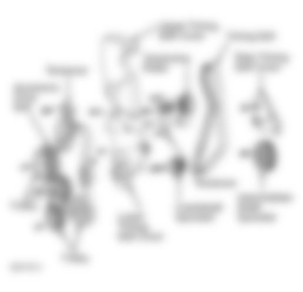
Fig. 51: Audi A4 1998 - Component Locations - Releasing Timing Belt Tension
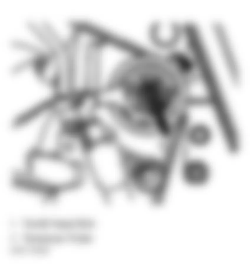

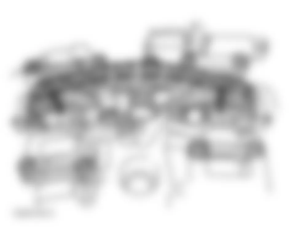
Fig. 54: Audi A4 1998 - Component Locations - New Camshaft Drive Chain Install Dimensions
Audi A4 1998 - Inspection
Check camshaft bearing oil clearance. See CAMSHAFT table under ENGINE SPECIFICATIONS. If oil clearance is not within specification, install new camshaft and recheck clearance. If clearance still exceeds specification, replace cylinder head. Check camshaft end play. See VALVE TRAIN under OVERHAUL.
CAUTION: If cam followers are charged with oil, allow 30 minutes for followers to bleed down before starting engine. Pistons may strike valves, resulting in bent valves.
Audi A4 1998 - Installation
- Place camshafts in cylinder head. Ensure lobes for No. 1 cylinder are pointed upward. See Fig. 48. Fit drive chain onto both camshafts relative to the marks. Replace chain tensioner rubber/metal gasket and coat shaded area lightly with sealant (D 454 300 A2). See Fig. 56. Slide chain tensioner between drive chain.
NOTE: Take note of dowel sleeves. - Oil running surfaces of camshafts. Place camshafts with drive chain in cylinder head. Tighten chain tensioner to 10 Nm (7 ft. lbs). Tighten camshaft bearing caps No. 2 and 4 evenly to 10 Nm (7 ft. lbs). Install both bearing caps at chain sprockets for intake and exhaust camshafts. Ensure camshafts are positioned correctly. Tighten bearing caps to 10 Nm (7 ft. lbs). Remove retainer for chain tensioner (3366).
- Lightly coat hatched area of double bearing cap with sealant (D 454 300 A2). See Fig. 57. Install and tighten to 10 Nm (7 ft. lbs.), remember dowel sleeves.
- Install remaining bearing caps and tighten to 10 Nm (7 ft. lbs.), remember dowel sleeves. Check position of marks made on camshafts sprockets relative to one another (positioning should be close to prior to removal). See Fig. 53. If a new chain is being installed, distance between Notch "A" and "B" must equal 16 drive chain rollers. Notch "A" is slightly off set inward toward drive chain roller (1). See Fig. 54.
- To complete installation, reverse removal procedure. If cam followers are charged with oil, allow 30 minutes for followers to bleed down before starting engine.
NOTE: When installing the bearing caps, ensure that the cap markings can be read from the intake side of the cylinder head.
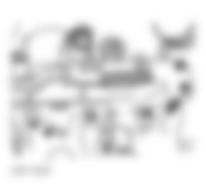
Fig. 57: Audi A4 1998 - Component Locations - Applying Sealant (D 454 300 A2) To Double Bearing Cap

Audi A4 1998 - CAMSHAFT OIL SEALS
CAUTION: DO NOT turn crankshaft or camshaft with timing belt removed. Valve damage may result.
CAUTION: DO NOT allow camshaft to turn when removing camshaft sprocket bolt.
Audi A4 1998 - Removal (Exhaust Cam)
- Remove upper timing belt cover. Place crankshaft at TDC with No. 1 cylinder on compression stroke. Release tensioner, using Torx? T45 bit, loosen bolt (1) at timing belt tensioner. Push timing belt tensioner pulley (2) downward and remove timing belt from camshaft sprocket. See Fig. 49-Fig. 51 .
- Turn crankshaft back slightly. Using Camshaft Holder (3036), remove camshaft sprocket bolt. Remove camshaft sprocket. Install camshaft sprocket bolt and washer until bolt comes to a stop (hand tight) against camshaft. See Fig. 58.
- Unscrew inner part of (2085) oil seal extractor 2 turns (approx. 3 mm) out of the outer section and lock with knurled screw. Lubricate threaded head of oil seal extractor, place in position and while exerting firm pressure, screw as far as possible into oil seal. See Fig. 59.
- Loosen knurled screw and turn inner part against crankshaft until oil seal is pulled out.
Fig. 58: Audi A4 1998 - Component Locations - Camshaft Sprocket bolt Installed In Camshaft
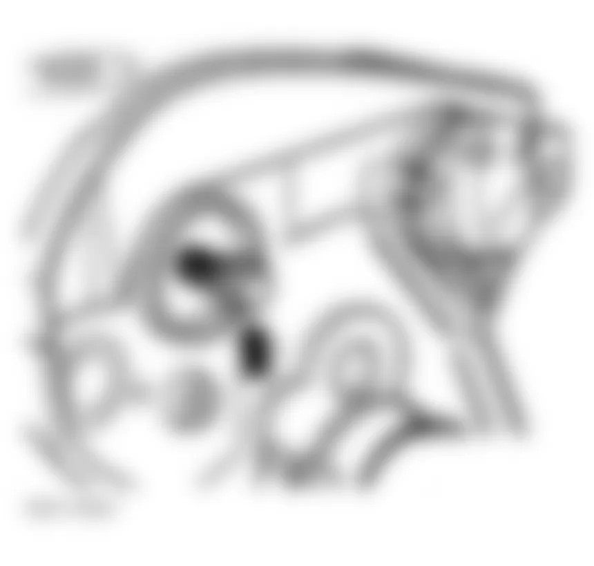
Fig. 59: Audi A4 1998 - Component Locations - Installing Seal Puller (2085)
Audi A4 1998 - Installation
Coat new seal lip lightly with engine oil. DO NOT oil outer circumference of oil seal. Using guide sleeve (3241/2), slide seal until flush with head. See Fig. 60. Using seal installer with press sleeve (3241/1) and bolt (3241/5), install new camshaft oil seal flush into cylinder head. See Fig. 61. Install CMP sensor. To complete installation, reverse removal procedure.
Fig. 60: Audi A4 1998 - Component Locations - Installing Guide Sleeve (3241/2) Onto Camshaft
Audi A4 1998 - Removal (Intake Cam)
- Remove upper timing belt cover.
- Unbolt Camshaft Position (CMP) sensor housing. Remove CMP sensor-to-rotor bolt. Carefully pry off rotor. See Fig. 62.
- Screw tool (2058/1 bolt) into camshaft. See Fig. 63. Unscrew inner part of (2058) oil seal extractor 2 turns (approx. 3 mm or 0.118") out of outer part and lock with Knurled screw. See Fig. 64.
- Lubricate thread head of oil seal extractor, place it in position while applying firm pressure screw it as far as into oil seal. Loosen knurled screw and turn inner part of extractor against camshaft until oil seal has been extracted.
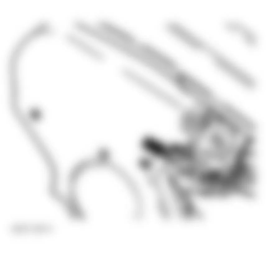
Fig. 63: Audi A4 1998 - Component Locations - Installing Adaptor (2085/1) Into Intake Camshaft

Fig. 64: Audi A4 1998 - Component Locations - Installing Seal Puller (2085)
Audi A4 1998 - Installation
Coat new seal lip lightly with engine oil. DO NOT oil outer circumference of oil seal. Using guide sleeve (3241/2), slide seal until flush with head. See Fig. 65. Using seal installer with press sleeve (3241/1) and bolt (3241/3), install new camshaft oil seal flush into cylinder head. See Fig. 66. Install CMP sensor, tighten shutter wheel for sensor to 25 Nm (18 ft. lbs.) and the Camshaft Position (CMP) sensor housing to 10 Nm (7 ft. lbs.). To complete installation, reverse removal procedure.
Fig. 65: Audi A4 1998 - Component Locations - Installing Guide Sleeve (3241/2) Over Intake Cam
Audi A4 1998 - CORE PLUG (CYLINDER HEAD)
CAUTION: Ensure core plug (sealing cap) is installed in cylinder head.
Audi A4 1998 - Removal
Removal procedure of core plug not provided by manufacturer at this time.
Audi A4 1998 - Installation
Coat outside circumference of core plug (sealing cap) with sealant (AMV 188 001 02). Using needle bearing drift (VW295), drive in core plug until outside rim is flush with end of chamfer in cylinder head. See Fig. 67.
Fig. 67: Audi A4 1998 - Component Locations - Identifying Installed Depth Of Core Plug (Sealing Cap)
Audi A4 1998 - CRANKSHAFT FRONT OIL SEAL
NOTE: For help in identifying components and component locations, refer to illustration. See Fig. 68.
Audi A4 1998 - Removal
- Remove timing belt. See TIMING BELT.
- Remove crankshaft toothed belt sprocket, by counter-holding sprocket with locking fixture (3099) tool. See Fig. 69. To guide oil seal extractor, screw bolt from tool kit (3083) as far into crankshaft as possible. See Fig. 70.
- Unscrew inner part of (2085) oil seal extractor 2 turns (approx. 3 mm) out of the outer section and lock with knurled screw. Lubricate threaded head of oil seal extractor, place in position and while exerting firm pressure, screw as far as possible into oil seal. See Fig. 71.
- Loosen knurled screw and turn inner part against crankshaft until oil seal is pulled out.
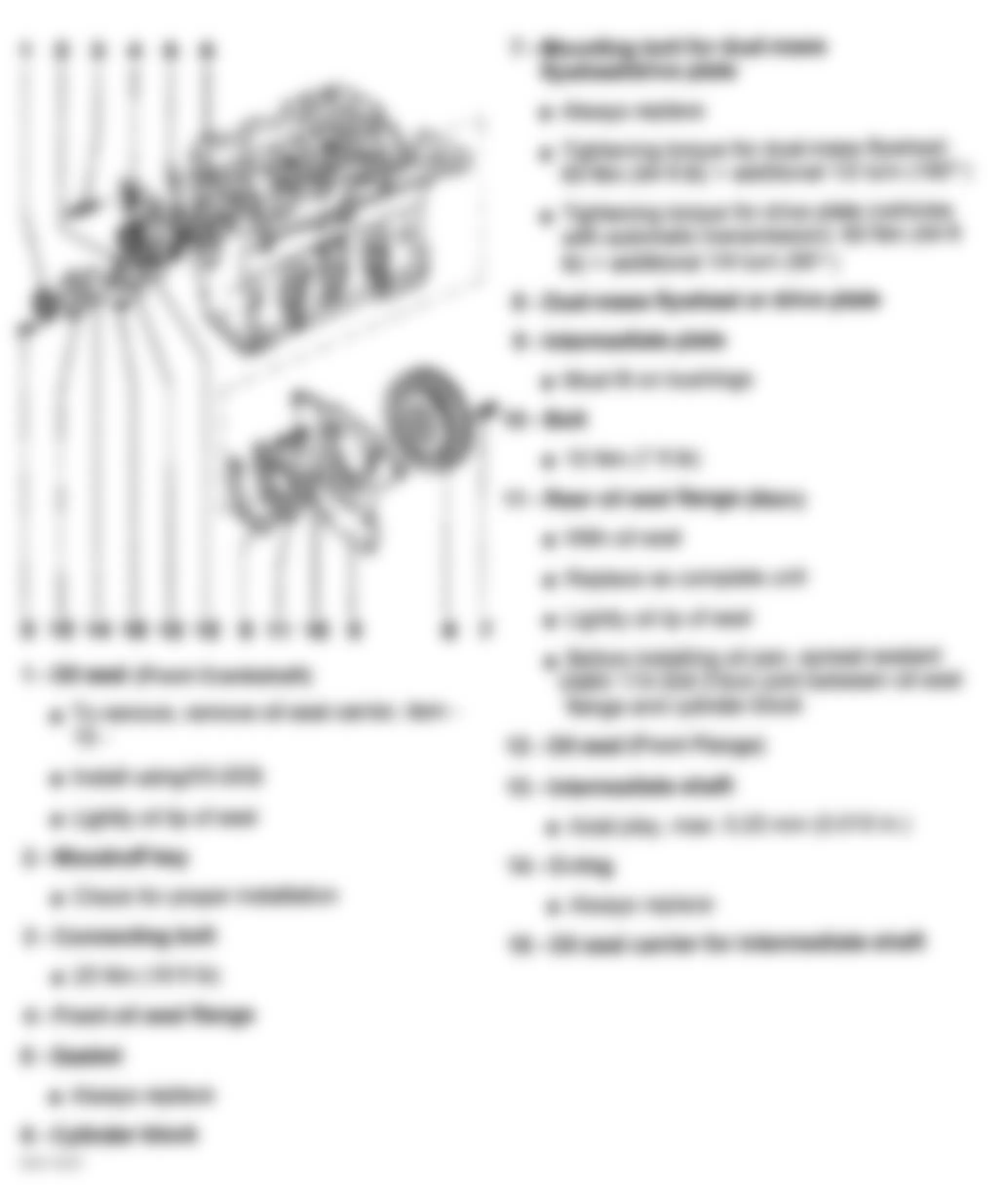
Fig. 69: Audi A4 1998 - Component Locations - Removing Crankshaft Tooth Timing Belt Sprocket (3099)

Fig. 71: Audi A4 1998 - Component Locations - Removing Crankshaft Seal With (2085)
Audi A4 1998 - Installation
Lubricate lip of new seal. Place guide sleeve from Seal Installer (3083) onto crankshaft. Push oil seal over guide sleeve. Press seal completely into position with press sleeve (3083). See Fig. 72 and Fig. 73 . Reinstall crankshaft toothed belt sprocket, by holding sprocket with 3099 tool. See Fig. 69. To complete installation, reverse removal procedure. See TORQUE SPECIFICATIONS.

Audi A4 1998 - CRANKSHAFT REAR OIL SEAL
NOTE: Crankshaft rear oil seal and carrier are serviced as an assembly.
NOTE: For help in identifying components and component locations, refer to illustration. See Fig. 68.
Audi A4 1998 - Removal & Installation
- Remove transmission. For M/T, see appropriate article in CLUTCHES. For A/T, see TRANSMISSION REMOVAL & INSTALLATION article in TRANSMISSION SERVICING. Remove drive plate (A/T) or dual-mass flywheel (M/T).
- Remove crankshaft oil seal carrier bolts and remove carrier with oil seal. Lightly oil lip with clean engine oil. Install NEW oil seal with carrier using supplied sleeve. Tighten crankshaft oil seal carrier bolts to 25 Nm (18 ft. lbs). See TORQUE SPECIFICATIONS.
Audi A4 1998 - CYLINDER HEAD
CAUTION: DO NOT start engine for about 30 minutes after installing camshafts. Hydraulic valve lifters must settle or valves may strike pistons. Rotate crankshaft by hand 2 revolutions before starting engine to ensure valves do not strike pistons.
Audi A4 1998 - Removal
- Release fuel pressure. See FUEL PRESSURE RELEASE. Disconnect negative battery cable. Label and disconnect electrical connectors and vacuum hoses. Drain coolant. See DRAINING COOLING SYSTEM. Remove cover for fuel injectors, wrap a rag around fuel supply and fuel return lines. Disconnect fuel lines at fuel rail connector. See Fig. 22. Seal fuel line to prevent dirt entry. See Fig. 80.
- Disconnect power steering cooling coil located at lower left of radiator. Drain coolant from radiator. See Fig. 9. Disconnect lower radiator hose.
- Disconnect intake air ducting located near radiator support. Disconnect headlight and turn signal electrical connectors. Disconnect coolant fan thermal switch located near lower coolant hose on left side of radiator.
- Pull cover for power steering fluid reservoir upward. Disconnect 4 harness connectors located under cover. Disconnect anti-theft alarm connector at upper left cowl. Disconnect coolant hose at upper left side of engine.
- Disconnect both horn connectors. See Fig. 23. Attach Alignment Tools to chassis. Remove bolts securing front of body to vehicle. See LOCK CARRIER. Slide front of body forward onto alignment tool. This will allow servicing of front engine components and facilitate removal of cylinder head.
- Disconnect both ignition coil power output stages harness connectors. Disconnect EVAP canister purge regulator valve from bracket and disconnect electrical connector. Disconnect wastegate by-pass regulator valve electrical connector. Remove intake air duct between air cleaner and turbocharger. See Fig. 110-Fig. 112 .
- Pry rubber sleeve off on air cleaner housing and disconnect Mass Airflow (MAF) sensor electrical connector. Disconnect EVAP canister hose connections. Remove air cleaner. See Fig. 32.
- Remove timing belt. See TIMING BELT. Disconnect ignition coils and ground wire from cylinder head valve cover and set aside. Cut cable tie on cylinder head valve cover and set wiring aside.
- Disconnect crankcase breather hose at wastegate, Disconnect engine coolant temperature sensor on rear of cylinder head. Disconnect accelerator pedal. Disconnect Camshaft Position (CMP) sensor on front of cylinder head. See Fig. 62.
- Disconnect coolant expansion tank. Disconnect hoses from left coolant line over intake manifold.
- Remove intake manifold and manifold support. See INTAKE MANIFOLD. Disconnect coolant line at rear of cylinder head. Disconnect heated oxygen sensor connector at left side of plenum and set aside. Disconnect turbocharger oil and coolant lines and front pipe on top of turbocharger. See TURBOCHARGER.
NOTE: When valve cover has been removed, take note of oil deflector positioning. - Disconnect oil and coolant lines and front pipe from lower part of turbocharger. Disconnect exhaust system bracket on transmission, then disconnect front pipe from turbocharger. Remove cylinder head valve cover, remove cylinder head bolts using sequence. Loosen head bolts a little at a time, till all bolts are loose. See Fig. 75. Remove cylinder head from vehicle.
Audi A4 1998 - Inspection
Thoroughly clean all gasket mating surfaces. Check cylinder head for warpage. Maximum warpage is .004" (.100 mm). Check minimum cylinder head height and replace cylinder head (if necessary). See CYLINDER HEAD under OVERHAUL, also see CYLINDER HEAD under ENGINE SPECIFICATIONS.
Audi A4 1998 - Installation
CAUTION: If cam followers or camshaft have been removed and followers are charged with oil, allow 30 minutes for followers to bleed down before starting engine. Pistons may strike valves, resulting in bent valves.
NOTE: DO NOT reuse antifreeze after replacing cylinder block, cylinder head, head gasket, radiator and/or heater core.
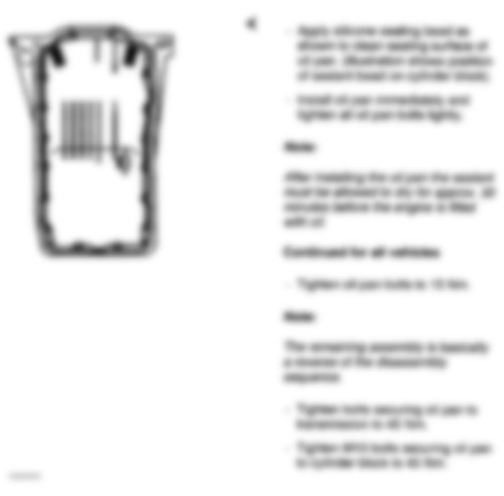
- Ensure part number on cylinder head gasket faces up. Install gasket on cylinder block. DO NOT use any type of sealant. Align camshaft timing marks and position crankshaft at TDC. See TIMING BELT.
- Install guide pins (VAG 3070 tool set) in head bolt holes No. 8 and 10. Carefully position cylinder head on cylinder. Install remaining head bolts finger tight. Remove guide pins with guide pin removal tool from (VAG 3070) and install remaining bolts. Tighten cylinder head bolts (in 4 steps) in sequence to specification. See Fig. 74. Also see TORQUE SPECIFICATIONS. To complete installation, reverse removal procedure. Before installation of valve cover apply a thin layer of sealer (D 454 300 A2) at the points of valve cover where leakage may occur. See Fig. 76.
Fig. 74: Audi A4 1998 - Component Locations - Cylinder Head Bolt Loosening Sequence
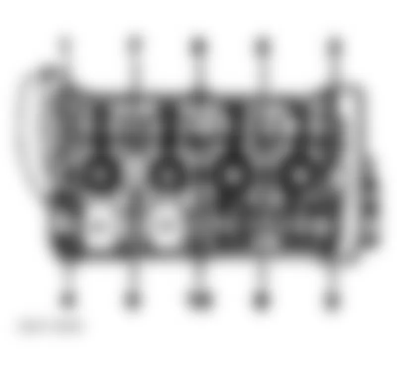
Fig. 75: Audi A4 1998 - Component Locations - Cylinder Head Bolt Tightening Sequence
Audi A4 1998 - DRIVE PLATE (A/T) & FLYWHEEL (M/T) Removal
NOTE: The following procedure is given assuming the transmission has been removed or the engine has been removed for servicing.
NOTE: For flywheel (M/T) pilot needle bearing inspection . See PILOT NEEDLE BEARING (M/T).
- Mark the position of the drive plate (A/T), also marking the positions of the washer (1) and the shim (2) between the drive plate and the crankshaft flange. See Fig. 77. Loosen the bolts in a cross pattern and remove drive plate or flywheel.
Fig. 77: Audi A4 1998 - Component Locations - Identifying Washer, Driveplate & Shim
Audi A4 1998 - Installation
- Install driveplate or flywheel. See Fig. 77. Using 3 of the old bolts inserted into flange, evenly spaced torque to 30 Nm (22 ft. lbs.) Check dimension "A" at 3 points. Specification is approximately 12.3 mm (0.484 INCHES). See Fig. 79.
NOTE: Only one shim of the proper size may be used. Tighten flange bolts in a cross pattern. - If specification is incorrect, replace shim to obtain proper dimension. Once specification is attained: install NEW bolts and torque in a criss-cross pattern to 60 Nm (44 ft. lbs.) and 1/4 turn (90?) further (Additional 1/4 turn can be done in several steps).
Fig. 79: Audi A4 1998 - Component Locations - Calculating Dimension For Shim Size
Audi A4 1998 - INTAKE MANIFOLD
NOTE: Obtain radio code before disconnecting battery. Remove engine, without transmission, through front of engine compartment.
Audi A4 1998 - Removal & Installation
- Remove battery. Remove lower engine shield (noise insulator). See Fig. 2. Drain coolant, see DRAINING COOLING SYSTEM.
WARNING: The cooling system is pressurized when the engine is warm. When opening the expansion tank, wear gloves and other appropriate protection, cover the cap with a cloth and open carefully to relieve system pressure slowly. - Remove cover for fuel injectors. Remove bolts securing fuel rail to intake manifold. Remove fuel injectors and rail together and rest aside on a clean shop towel. See Fig. 80.
- Disconnect harness connectors from around air cleaner box. Remove air cleaner box. See Fig. 32. Disconnect Cam Position (CMP) Sensor. See Fig. 62. Disconnect accelerator pedal cable from the throttle valve control module. DO NOT remove locking clip on accelerator pedal cable. See Fig. 35. Disconnect Leak Detection Pump (LDP) vacuum lines. See Fig. 36. Disconnect vacuum lines at brake booster.
- Disconnect coolant hoses at upper coolant line. See Fig. 80. Disconnect upper coolant line at intake line and rear coolant flange at rear of cylinder head. See Fig. 81.
- Disconnect crank case ventilation hose (1) at manifold. Remove brace (2). See Fig. 82. Remove oil dipstick, unbolt intake manifold at flange and remove manifold. Block intake ports in cylinder head with clean shop towels. To install, reverse removal procedure. Tighten bolts to specification. See TORQUE SPECIFICATIONS.
Fig. 80: Audi A4 1998 - Component Locations - Identifying Intake Manifold & Fuel Rail Components
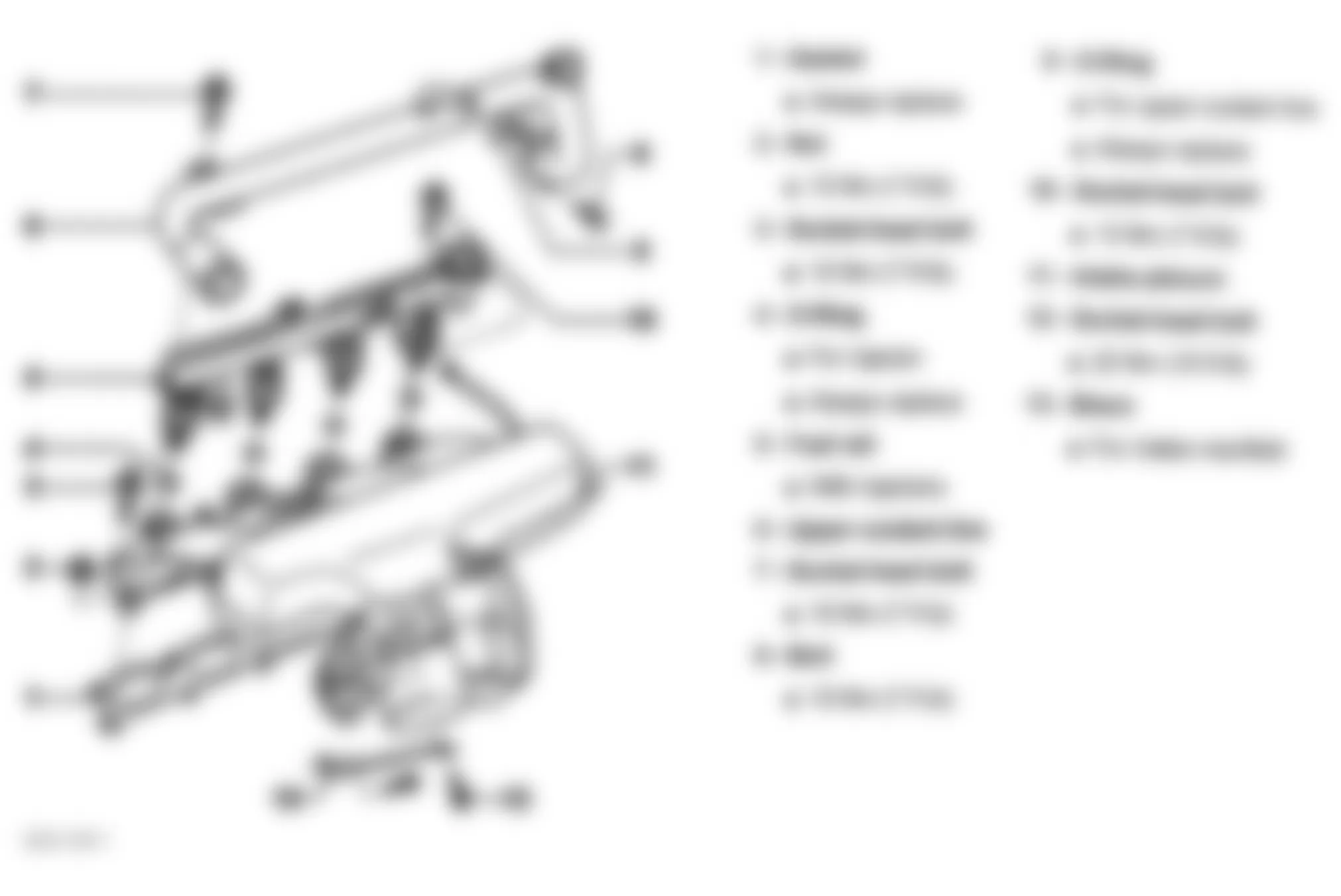
Fig. 82: Audi A4 1998 - Component Locations - Identifying Brace & Hose Connected To Intake Manifold
Audi A4 1998 - EXHAUST MANIFOLD
Removal and installation procedures are not available from manufacturer. See TURBOCHARGER. On installation, tighten bolts to specification. See TORQUE SPECIFICATIONS.
Audi A4 1998 - HYDRAULIC VALVE ADJUSTERS
WARNING: ALWAYS release fuel pressure before disconnecting fuel injection related component. DO NOT allow fuel to contact engine or electrical components.
CAUTION: DO NOT start engine for about 30 minutes after installing camshafts. Hydraulic valve lifters must bleed down or valves may strike pistons. Rotate crankshaft by hand 2 full revolutions before starting engine to ensure valves do not strike pistons.
NOTE: Valve lifters are not repairable or adjustable. Replace faulty lifters. Irregular valve train noise is normal when starting engine.
Audi A4 1998 - Checking
- Start engine and run until cooling fan cycles at least once. Increase engine speed to 2500 RPM for 2 minutes or test drive vehicle and observe valve train noise. If valve train noise is still considered noisy, go to next step.
- Turn engine off. Remove valve cover. Rotate crankshaft until camshaft lobes point upward on lifter being checked. Using a wooden or plastic wedge, push down on top of lifter. See Fig. 83. Try inserting a .008" (.20 mm) feeler gauge between top of lifter and camshaft. If feeler gauge fits between top of lifter and camshaft, replace faulty lifter.
Fig. 83: Audi A4 1998 - Component Locations - Placement Of Wedge On Lifter (Push Down)

Audi A4 1998 - OIL PAN - A4 Removal & Installation
- To bring lock carrier into service position, see LOCK CARRIER.
- Raise and support vehicle. Drain engine oil into suitable container.
- Remove noise insulation panel from under engine.
- For oil pan removal and installation procedures, refer to Fig. 84-Fig. 93 .
Fig. 84: Audi A4 1998 - Component Locations - Replacing Oil Pan (A4 - 1 Of 10)
Fig. 85: Audi A4 1998 - Component Locations - Replacing Oil Pan (A4 - 2 Of 10)
Fig. 86: Audi A4 1998 - Component Locations - Replacing Oil Pan (A4 - 3 Of 10)
Fig. 87: Audi A4 1998 - Component Locations - Replacing Oil Pan (A4 - 4 Of 10)
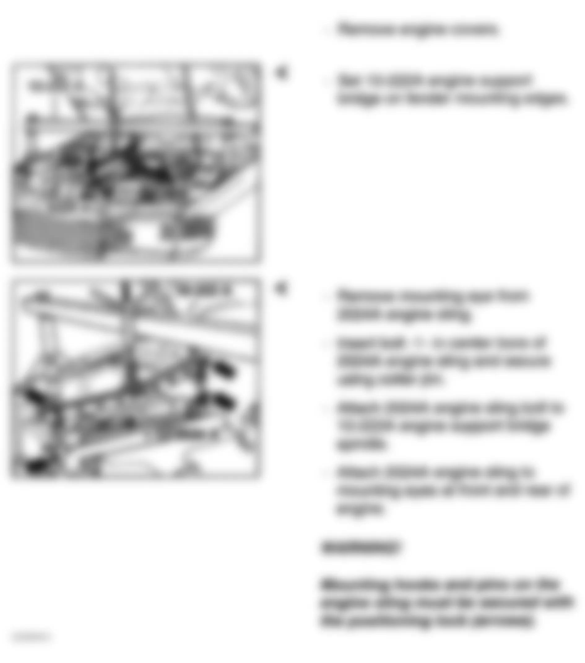
Fig. 88: Audi A4 1998 - Component Locations - Replacing Oil Pan (A4 - 5 Of 10)
CAUTION: Manufacturer recommends replacing subframe bolts if loosened or removed. Use NEW bolts during subframe installation.
Fig. 89: Audi A4 1998 - Component Locations - Replacing Oil Pan (A4 - 6 Of 10)
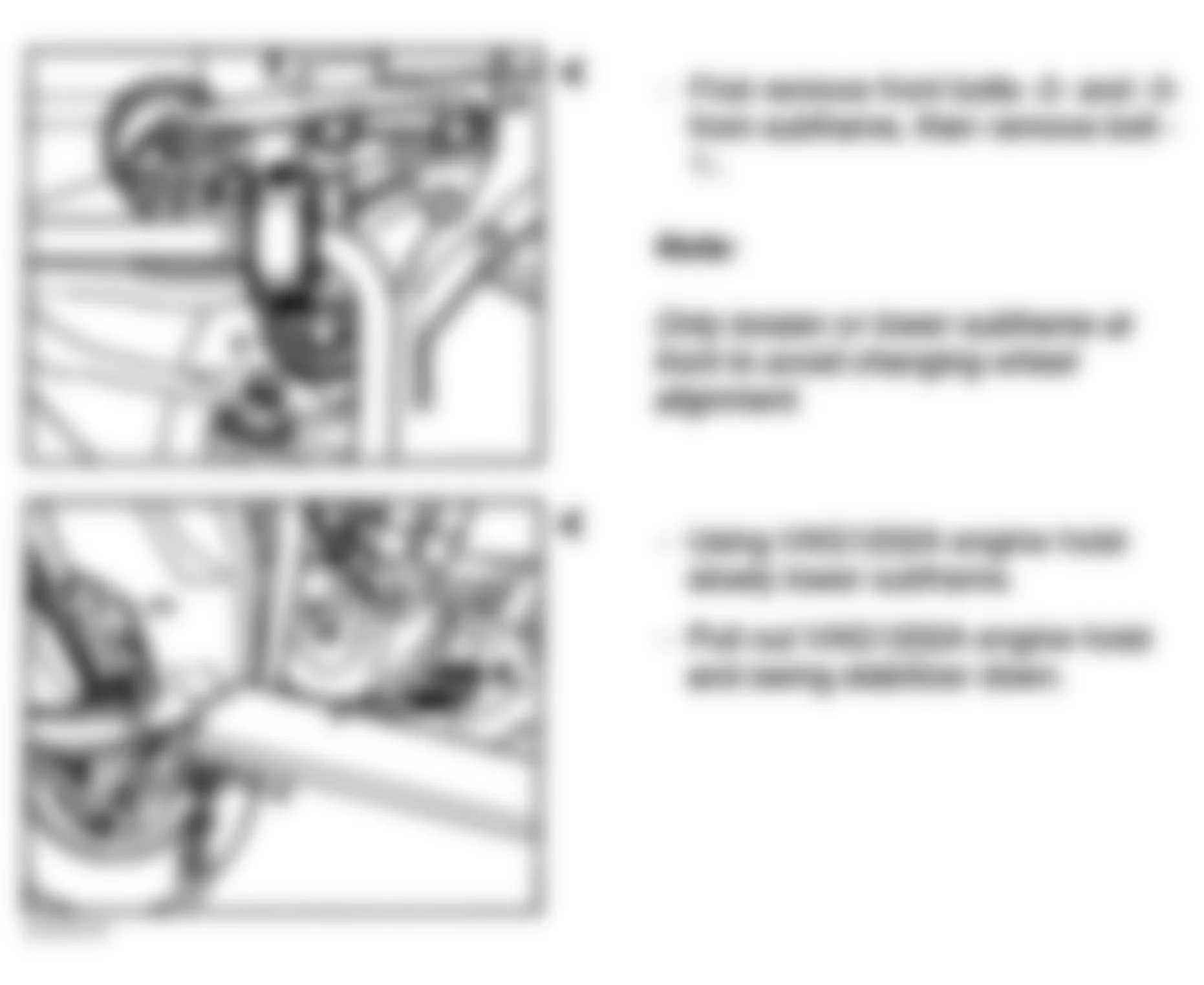
Fig. 90: Audi A4 1998 - Component Locations - Replacing Oil Pan (A4 - 7 Of 10)
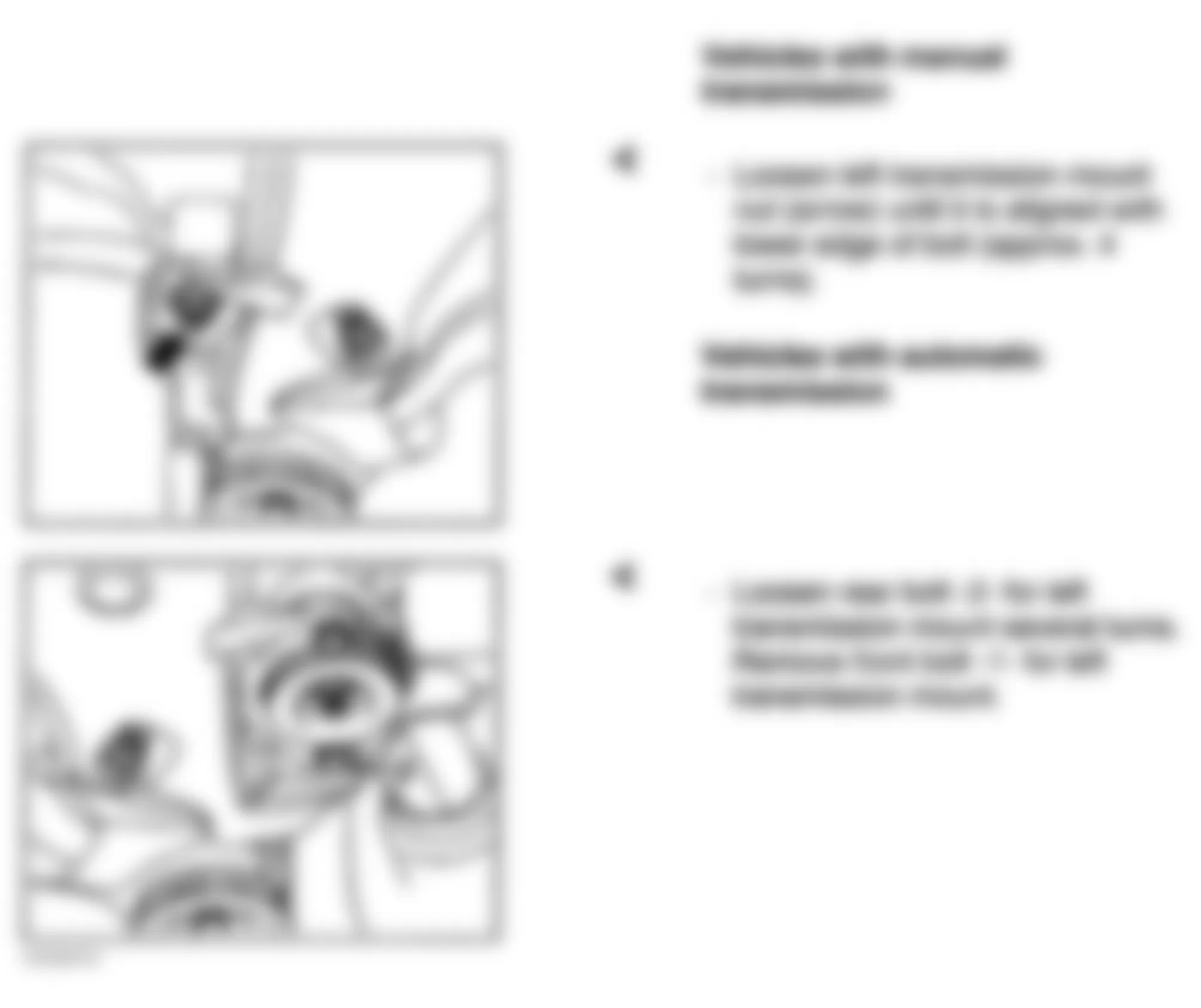
Fig. 91: Audi A4 1998 - Component Locations - Replacing Oil Pan (A4 - 8 Of 10)
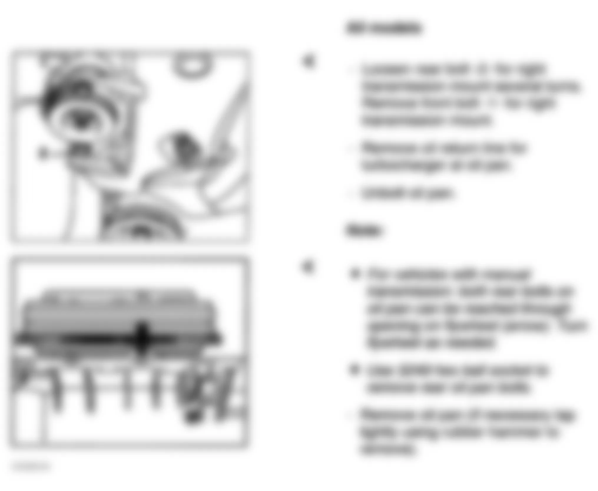
Fig. 92: Audi A4 1998 - Component Locations - Replacing Oil Pan (A4 - 9 Of 10)
CAUTION: Manufacturer recommends replacing subframe bolts if loosened or removed. Use NEW bolts during subframe installation.
NOTE: During installation, tighten new subframe bolts Nos. 2 and 3 to 55 ft. lbs. (75 N.m). Tighten new subframe bolt No. 1 to 81 ft. lbs. (110 N.m), then tighten an additional 90 degree turn. See Fig. 89 for bolt identification.
Fig. 93: Audi A4 1998 - Component Locations - Replacing Oil Pan (A4 - 10 Of 10)

Audi A4 1998 - OIL PAN - PASSAT Removal & Installation
- To bring lock carrier into service position, see LOCK CARRIER.
- Drain engine oil into suitable container.
- Remove accessory drive belt. See ACCESSORY DRIVE BELTS.
- Secure viscous fan coupling belt pulley with a punch 5 mm diameter. See Fig. 94. Remove viscous fan coupling securing bolt with 8 mm hex key (2). Remove viscous fan coupling with belt pulley.
- To remove and install oil pan, see Fig. 95-Fig. 101.
Fig. 94: Audi A4 1998 - Component Locations - Removing Viscous Fan Coupling Belt Pulley
Fig. 95: Audi A4 1998 - Component Locations - Replacing Oil Pan (Passat - 1 Of 7)
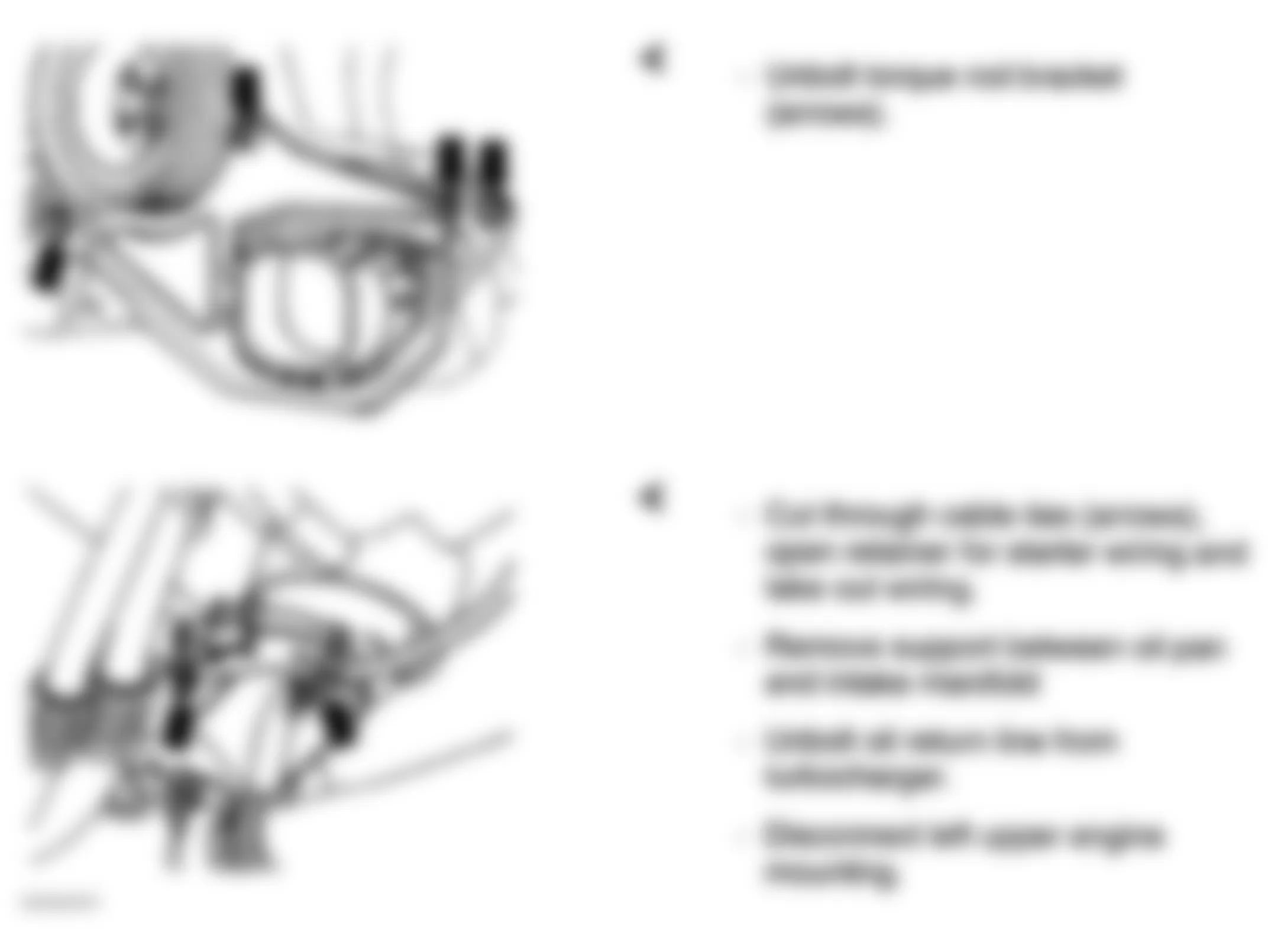
Fig. 96: Audi A4 1998 - Component Locations - Replacing Oil Pan (Passat - 2 Of 7)
CAUTION: Manufacturer recommends replacing subframe bolts if loosened or removed. Use NEW bolts during subframe installation.
NOTE: During installtion, tighten NEW subframe bolts Nos. 2 and 3 to 55 ft. lbs. (75 N.m). Tighten NEW subframe bolt No. 4 to 81 ft. lbs. (110 N.m), then tighten an additional 90 degree turn. See Fig. 97 for bolt identification.
Fig. 97: Audi A4 1998 - Component Locations - Replacing Oil Pan (Passat - 3 Of 7)
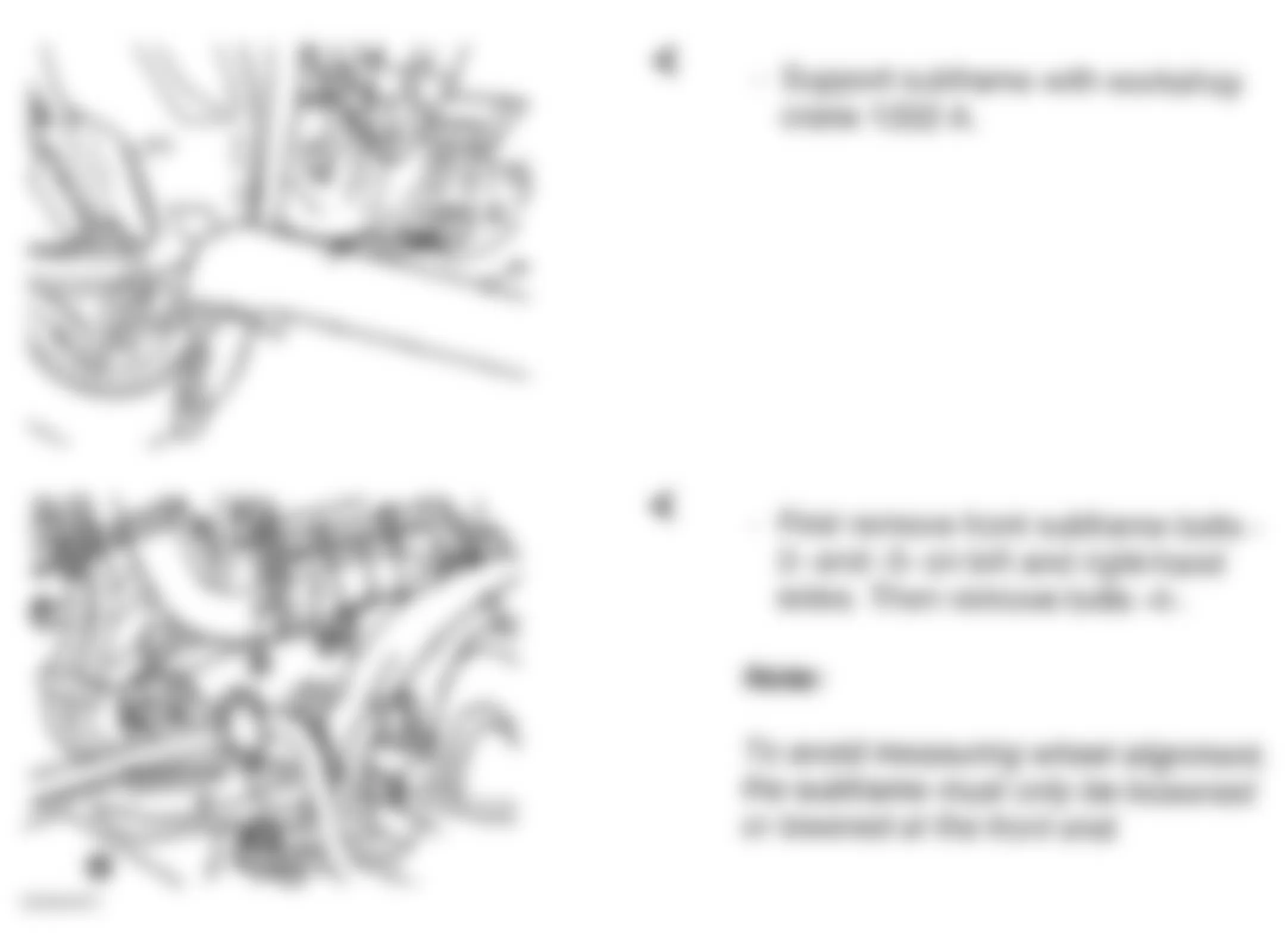
Fig. 98: Audi A4 1998 - Component Locations - Replacing Oil Pan (Passat - 4 Of 7)
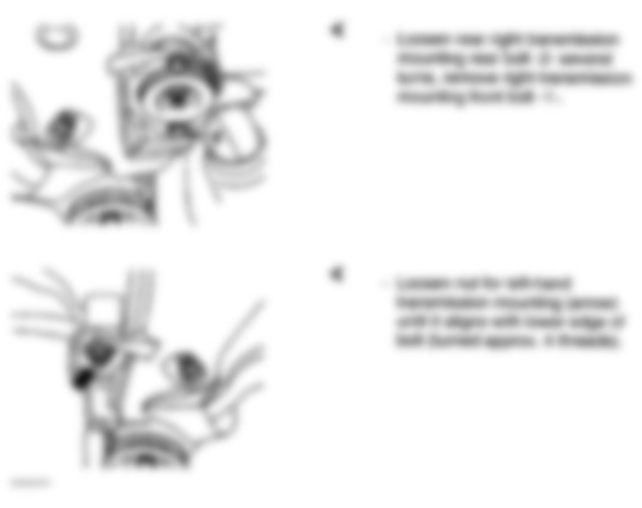
Fig. 99: Audi A4 1998 - Component Locations - Replacing Oil Pan (Passat - 5 Of 7)
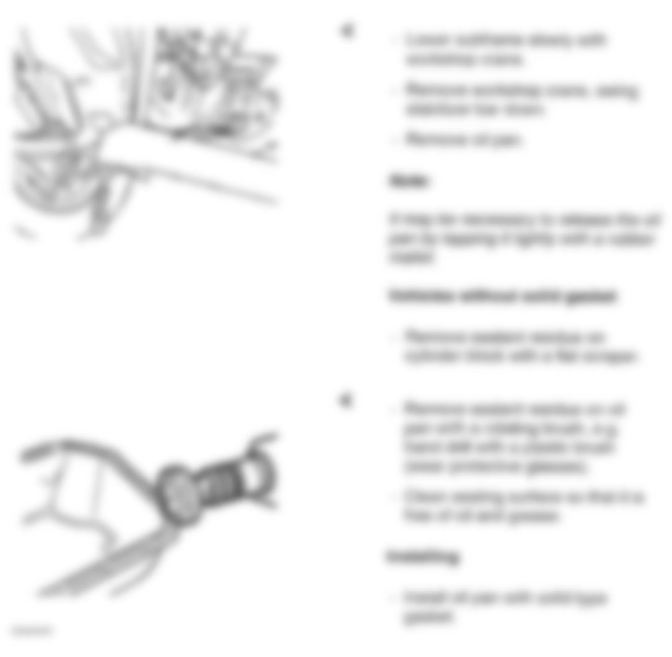
Fig. 100: Audi A4 1998 - Component Locations - Replacing Oil Pan (Passat - 6 Of 7)
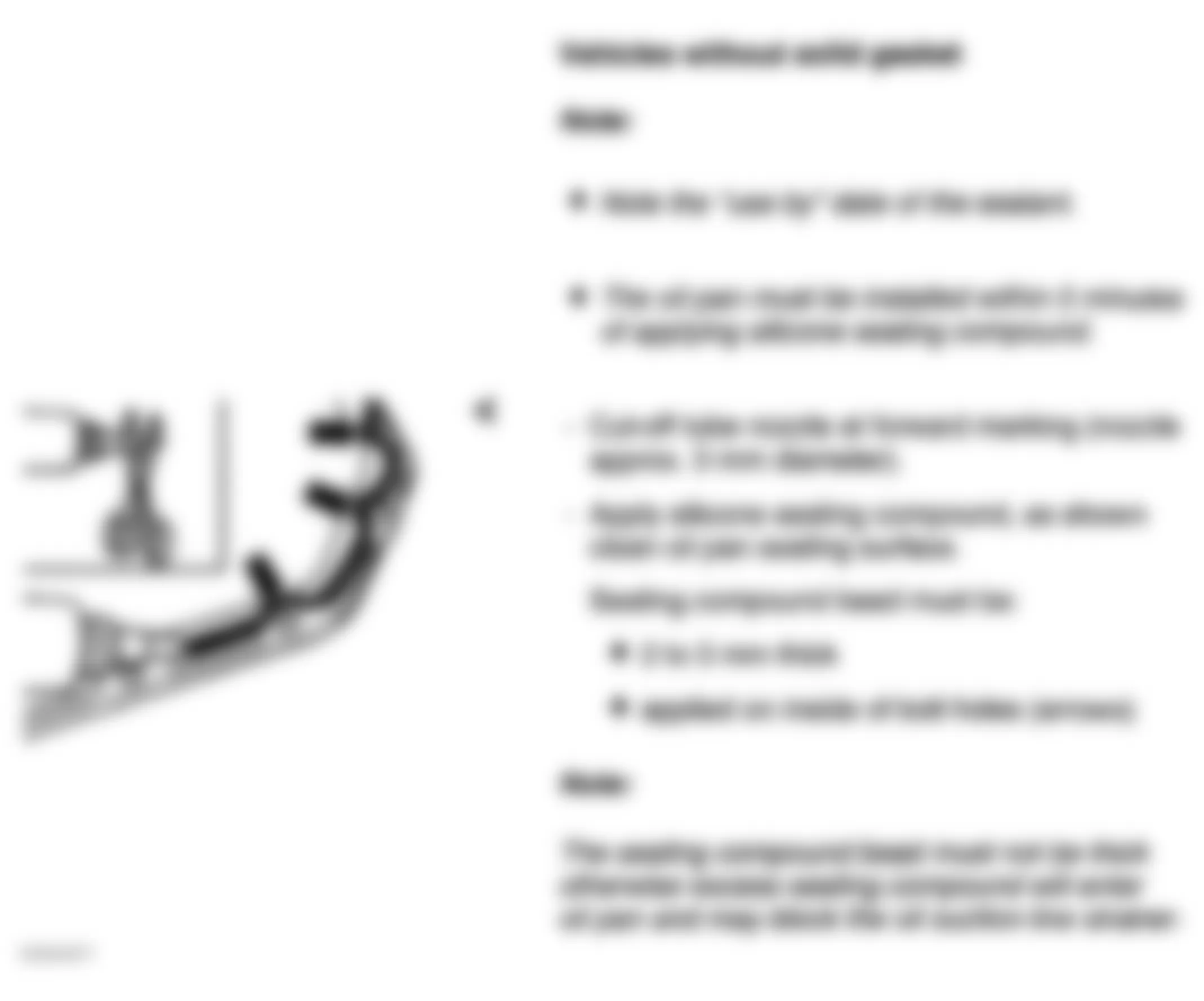
Fig. 101: Audi A4 1998 - Component Locations - Replacing Oil Pan (Passat - 7 Of 7)
Audi A4 1998 - PILOT NEEDLE BEARING (M/T) Removal & Installation
- Remove transmission. For M/T, see appropriate article in CLUTCHES. Remove flywheel (M/T).
- Using an appropriate puller, remove pilot needle bearing. See Fig. 102. To complete installation, reverse removal procedure. Use bearing driver (VW 207C) to install pilot needle bearing. See Fig. 103 and Fig. 104 . For flywheel installation. See DRIVE PLATE (A/T) & FLYWHEEL (M/T).
Fig. 102: Audi A4 1998 - Component Locations - Removing Pilot Needle Bearing
Fig. 103: Audi A4 1998 - Component Locations - Installing Pilot Needle bearing Using (VW 207C)
Fig. 104: Audi A4 1998 - Component Locations - Pilot Needle Bearing Insertion Depth (A=1.5 mm)
Audi A4 1998 - TIMING BELT
CAUTION: DO NOT turn crankshaft or camshaft with timing belt removed. Valve damage may result.
NOTE: For timing belt removal and installation procedures, see TIMING BELT REPLACEMENT - 1.8L (AEB & ATW ENGINES) article in ENGINES.
Audi A4 1998 - TURBOCHARGER
WARNING: The cooling system is pressurized when the engine is warm. When opening the expansion tank, wear gloves and other appropriate protection, cover the cap with a cloth and open carefully to relieve system pressure slowly.
NOTE: Obtain radio code before disconnecting battery. Remove engine, without transmission, through front of engine compartment. Always replace gaskets and self locking nuts.
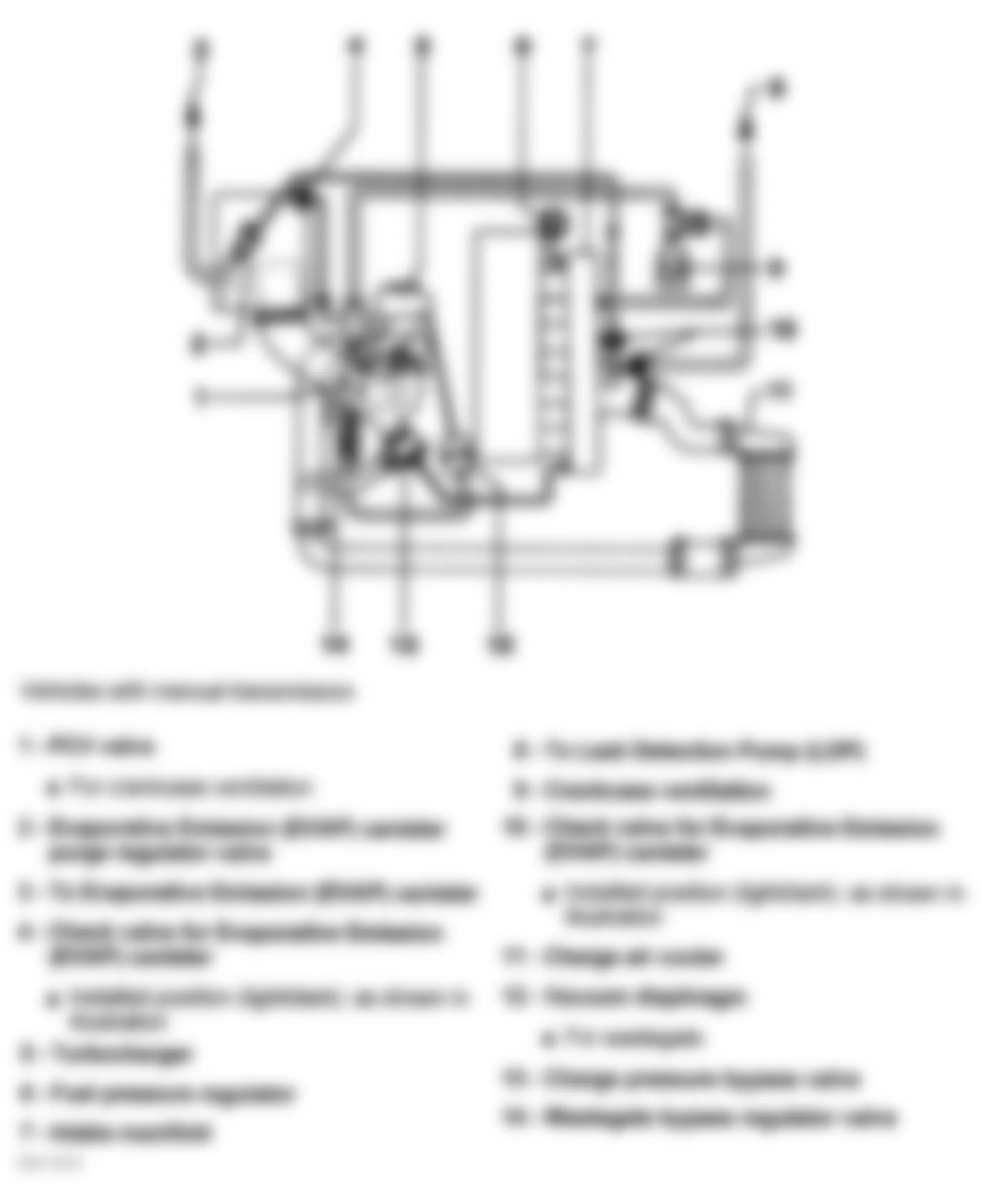
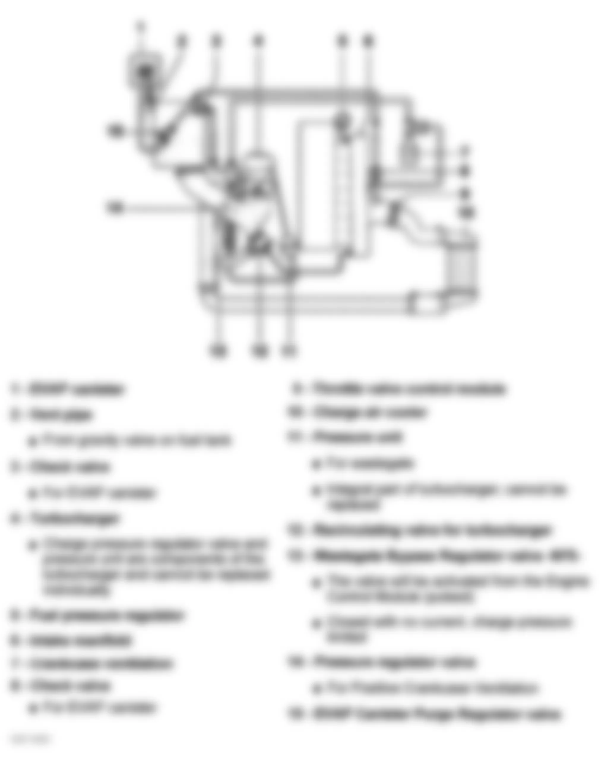
NOTE: For help in identifying components and component locations, refer to illustrations. See Fig. 105-Fig. 112.
Audi A4 1998 - Removal & Installation
- Remove battery. Remove engine cover(s). Raise vehicle, remove lower engine shield (noise insulator). See Fig. 2. Drain coolant, see DRAINING COOLING SYSTEM.
NOTE: DO NOT let hang by hoses, do not open the A/C system. - Unbolt A/C compressor, move compressor aside, support with wire.
- Unbolt turbo support bracket (2), disconnect oil return line (1) from turbo and move aside. Remove ducting from turbo (4 & 5). Remove pressure line banjo fitting (3). See Fig. 106.
- Disconnect hose from support for charge air pressure regulator valve. Unbolt bracket for coolant supply line at charge air pressure regulator valve. Remove air intake duct between cowl and air cleaner housing.
- Disconnect harness connectors from around air cleaner box. Remove air cleaner box. See Fig. 32.
- Unbolt crankcase ventilation hose (1). Unbolt oil supply line bolts (3) at heat shield. Remove heat shield (4). Remove sleeve (2) from coolant return hose. Remove turbo return hose at line to turbo. The line remains bolted to turbocharger. Unbolt the oil supply line (7) from turbo. See Fig. 107.
- Unbolt catalytic converter from turbo, remove bolts (5) from exhaust manifold. Position turbo to gain access to coolant supply line banjo fitting and remove. Remove turbocharger.
NOTE: Before tightening turbocharger, loosely bolt coolant supply line to vacuum diaphragm for air pressure regulator valve. Tighten banjo fitting, then tighten mounting bolts for bracket to proper torque. - To install, reverse removal procedure. Tighten bolts to specification. See TORQUE SPECIFICATIONS. For help in identifying intake ducting components, vacuum line routing and component locations, refer to illustrations. See Fig. 108-Fig. 112 .
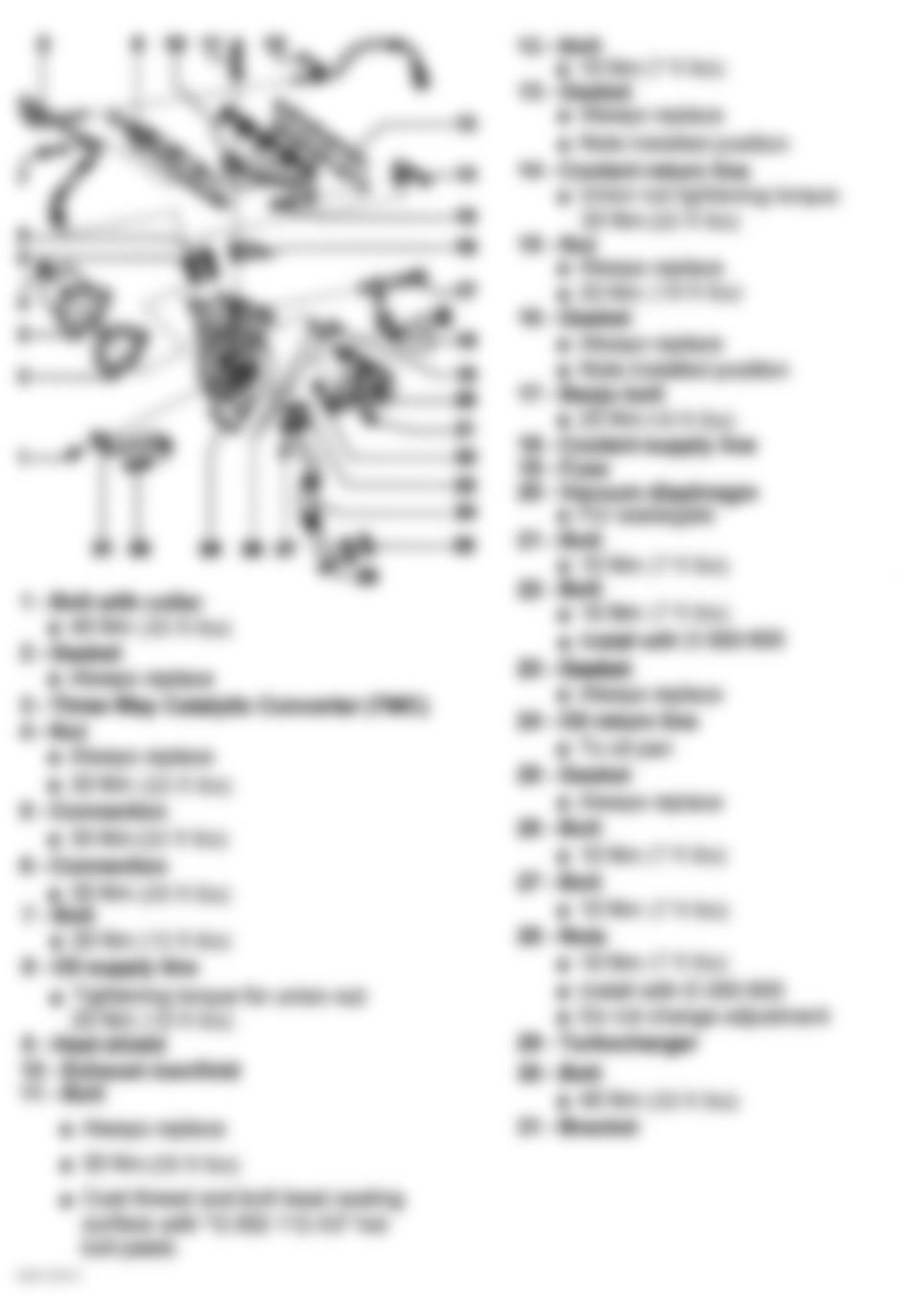
Fig. 106: Audi A4 1998 - Component Locations - Removing Turbocharger (1 of 2)
Fig. 107: Audi A4 1998 - Component Locations - Removing Turbocharger (2 of 2)
Fig. 108: Audi A4 1998 - Component Locations - Identifying Intake Ducting & Components (1 of 2)
Audi A4 1998 - VISCOUS FAN (ENGINE COOLING) Removal & Installation
- Raise vehicle, remove lower engine shield (noise insulator). See Fig. 2. Move lock carrier to service position. See LOCK CARRIER. Release tension off serpentine belt. See REMOVAL & INSTALLATION (SERPENTINE BELT).
- Remove viscous fan with pulley from its bearing. Use a drift punch to lock up the coupling/pulley (1). Using an 8 mm hex wrench (2) remove fasteners from viscous coupling, remove coupling and Pulley. See Fig. 113. To remove viscous fan bushing (bearing). See VISCOUS FAN BUSHING (BEARING). or go to next step.
- To install, reverse removal procedure. Ensure pulleys are free of debris. Bolt coupling/pulley to bracket/bearing, Using a torque wrench, tighten mounting bolts to 45 Nm (33 ft. lbs).
- Using a torque wrench tighten fan to viscous coupling to 10 Nm (7 ft. lbs).
- Start engine and check viscous fan and belt running condition.
Fig. 113: Audi A4 1998 - Component Locations - Removing Viscous Fan, Coupling & Pulley

Audi A4 1998 - VISCOUS FAN BUSHING (BEARING) Removal & Installation
- Raise vehicle, remove lower engine shield (noise insulator). See Fig. 2. Move lock carrier to service position. See LOCK CARRIER. Release tension off serpentine belt. See REMOVAL & INSTALLATION (SERPENTINE BELT). Remove viscous fan and pulley. See VISCOUS FAN (ENGINE COOLING).
- With fan and pulley removed, remove circlip (1) from bracket. See Fig. 114. Pull bearing out of bracket using (VAG 3367/3, 3350, and 3301). See Fig. 115.
- Press Bearing back into bracket using (VAG 3367/1, 3367/2, 3367/3, and 3301). SeeFig. 116.
- To complete install, reverse removal procedure. Ensure pulleys are free of debris. Bolt coupling/pulley to bracket/bearing, Using a torque wrench, tighten mounting bolts to 45 Nm (33 ft. lbs).
- Using a torque wrench tighten fan to viscous coupling to 10 Nm (7 ft. lbs).
- Start engine and check viscous fan and belt running condition.
Fig. 114: Audi A4 1998 - Component Locations - Identifying Location of Bearing & Circlip In Bracket
Fig. 115: Audi A4 1998 - Component Locations - Removing Bearing From Bracket
Fig. 116: Audi A4 1998 - Component Locations - Installing Bearing Into Bracket
Audi A4 1998 - OVERHAUL
CAUTION: DO NOT start engine for about 30 minutes after installing camshafts. Hydraulic valve lifters must bleed down or valves may strike pistons. Rotate crankshaft by hand 2 full revolutions before starting engine to ensure valves do not strike pistons.
Audi A4 1998 - CYLINDER HEAD Cylinder Head Resurfacing
Measure cylinder head warpage, measure at several points along gasket surface using straight edge and feeler gauge. See Fig. 117. If warpage exceeds specification, machine cylinder head. See CYLINDER HEAD table under ENGINE SPECIFICATIONS. If machining causes cylinder head height to be less than specification, replace cylinder head. When checking dimensions for cylinder head height, measure at (A) through the holes for the head bolts. See Fig. 118.
Fig. 117: Audi A4 1998 - Component Locations - Checking Cylinder Head For Warpage
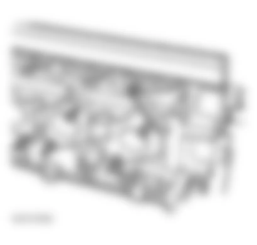
Fig. 118: Audi A4 1998 - Component Locations - Checking Cylinder Head Height
Audi A4 1998 - Valve Guides Checking
NOTE: Intake valve stem diameter differs from exhaust valve stem diameter. Use appropriate valve when measuring valve guide wear.
- To measure valve guide wear, attach dial indicator to cylinder head. Insert valve into guide until valve stem tip is even with top end of guide.
- Lightly push edge of valve head against dial indicator tip. Zero dial indicator. Push valve away from dial indicator, in direction opposite of camshaft axis.
- Maximum allowable deflection is .032" (.8 mm) on intake or exhaust valve. If deflection does not exceed specification, guide is okay. If deflection exceeds specification, recheck using new valve. If deflection still exceeds specification, replace worn guides. See Fig. 119.
Fig. 119: Audi A4 1998 - Component Locations - Checking Valve Guide Wear
Audi A4 1998 - Valve Guide Removal
NOTE: Hand lap valves check sealing, also check cylinder head sealing surface can be refaced. If a problem is found in either case, valve guides should not be replaced.
- Set the cylinder support (3361) as soon. See Fig. 120.
- Install mounting pins for cylinder head bolts (A) into threaded holes (2) and (3). See Fig. 120.
- Install pin (B) into relevant hole for valve angle. Outer inlet valves: 21.5 degrees, center Inlet valve: 15 degrees and exhaust valve: 20 degrees.
- Press worn valve guides out with drift (3360) from camshaft side. See Fig. 121.
- Lubricate new valve guides with oil. Using Valve Guide Installer (3360), press valve guide in cold cylinder head as far as guide will go (until shoulder makes contact) from camshaft side. DO NOT exceed one ton pressure. Using Valve Guide Reamer (3363), ream guides to proper stem-to-guide clearance. See CYLINDER HEAD table under ENGINE SPECIFICATIONS.
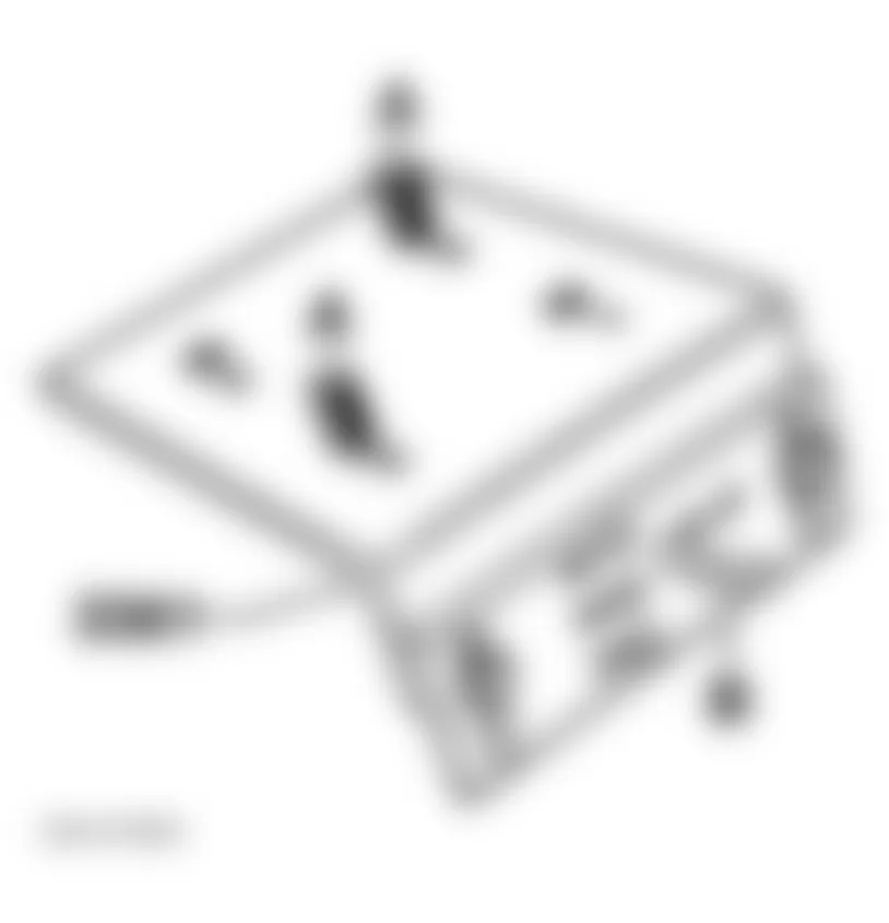
Fig. 121: Audi A4 1998 - Component Locations - Pressing Valve Guide From Cylinder Head
Audi A4 1998 - Valves Stem Seals Replacement (Head Installed)
- Remove camshafts. See CAMSHAFTS under REMOVAL & INSTALLATION.
- Remove valve lifters and place them with contact surface downward. During removal make sure lifters are not interchanged.
- Remove spark plugs with spark plug removal tool (3122B).
- Set piston of relevant cylinder to Bottom Dead Center (BDC).
- Screw VW pressure hose (653/3) into spark plug thread. See Fig. 122.
NOTE: DO NOT remove valve springs at this time. - Secure (3362) valve spring compressor to cylinder head with tool securing bolt and position installing tool for compressing valve springs to following positions. Outer intake valves: lower position, Center intake valve: upper position and Exhaust valve: lower position. See Fig. 122.
- Connect pressure hose to compressed air system supplying at least 6 bar (87 psi) and remove valve springs.
- Remove valve stem seals with puller (3364) for valve shaft seal. See Fig. 123.
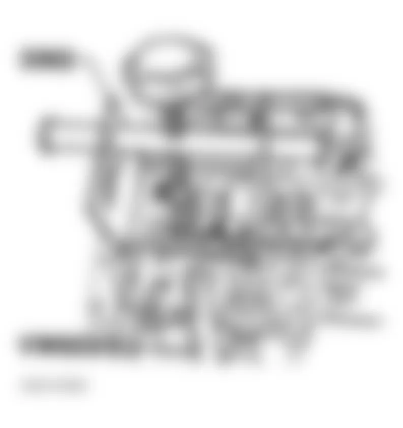
Fig. 123: Audi A4 1998 - Component Locations - Identifying Valve Stem Seal Puller (3364)
Audi A4 1998 - Installing Valves Stem Seals
- Slide plastic sleeve (A) supplied over relevant valve stem. This will prevent the new valve stem seal (B) from being damaged. See Fig. 124.
- Place new valve stem seal into installation tool (3365).
- Oil valve stem seal sealing lip and press carefully onto the valve guide. See Fig. 124. The assembly is basically a reverse of the dismantling sequence.
CAUTION: DO NOT start engine for about 30 minutes after installing camshafts. Hydraulic valve lifters must bleed down or valves may strike pistons. Rotate crankshaft by hand 2 full revolutions before starting engine to ensure valves do not strike pistons.
Audi A4 1998 - Valve Seats
NOTE: When repairing engines with leaking valves, it is not sufficient to replace or renew valve seats and valves. It is also necessary to check the valve guides for wear. This is particularly important on high mileage engines. The valve seats should only be refaced just enough to produce a perfect seating pattern. The maximum permissible refacing dimension must be calculated before beginning refacing. If the refacing dimension is exceeded, the function of the hydraulic valve lifters can no longer be guaranteed and the cylinder head should be replaced. If the valve is to be replaced as part of a repair, use a new valve for the calculation.
- Insert valve into guide. Press valve tightly against valve seat. Lay a straightedge across top of cylinder head. Measure distance between valve stem tip and bottom of straightedge. See Fig. 125. This is valve installed height. If a new valve is going to be installed, use new valve to make this measurement.
- This measurement determines installed valve height. Subtract measured distance from minimum specification. See MINIMUM VALVE INSTALLED HEIGHT table. If valve installed height is too low or too high, cam followers will not work correctly. If valve stem height is less than 1.339" (34.0 mm) on intake valve (outer), 1.327" (33.7 mm) intake valve (center), or 1.354" (34.4 mm) on the exhaust valve, install a new valve and measure again. See Fig. 126.
- If valve stem height measurement is still less than specification, replace cylinder head. If valve stem height exceeds specification, seat can be machined; however, DO NOT machine enough material away from seat to cause valve stem height to be less than minimum specification.
Fig. 125: Audi A4 1998 - Component Locations - Measuring Valve Installed Height

Audi A4 1998 MINIMUM VALVE INSTALLED HEIGHT
Application In. (mm) Intake Valve Outer 1.370 (34.80) Center 1.326 (33.70) Exhaust Valve 1.354 (34.40)
Audi A4 1998 - VALVE TRAIN Lifters (Cam Followers)
CAUTION: If lifters are charged with oil, allow 30 minutes to bleed down before starting engine. Pistons may strike valves, resulting in bent valves.
CAUTION: DO NOT start engine for about 30 minutes after installing camshafts. Hydraulic valve lifters must bleed down or valves may strike pistons. Rotate crankshaft by hand 2 full revolutions before starting engine to ensure valves do not strike pistons.
Test lifters, see VALVE LIFTERS under REMOVAL & INSTALLATION. If lifter(s) can be pushed down more than .007" (.20 mm), replace lifters.
Audi A4 1998 - Camshaft Axial Play (Audi)
Measure camshaft axial play (intake and exhaust) with lifter and camshaft chain removed. Measure with chain side camshaft bearing caps and cam sprocket side double bearing cap installed. See Fig. 127. Remove all other caps, note their locations for reassemble. See Fig. 128. Maximum wear limit .008" (.2 mm).
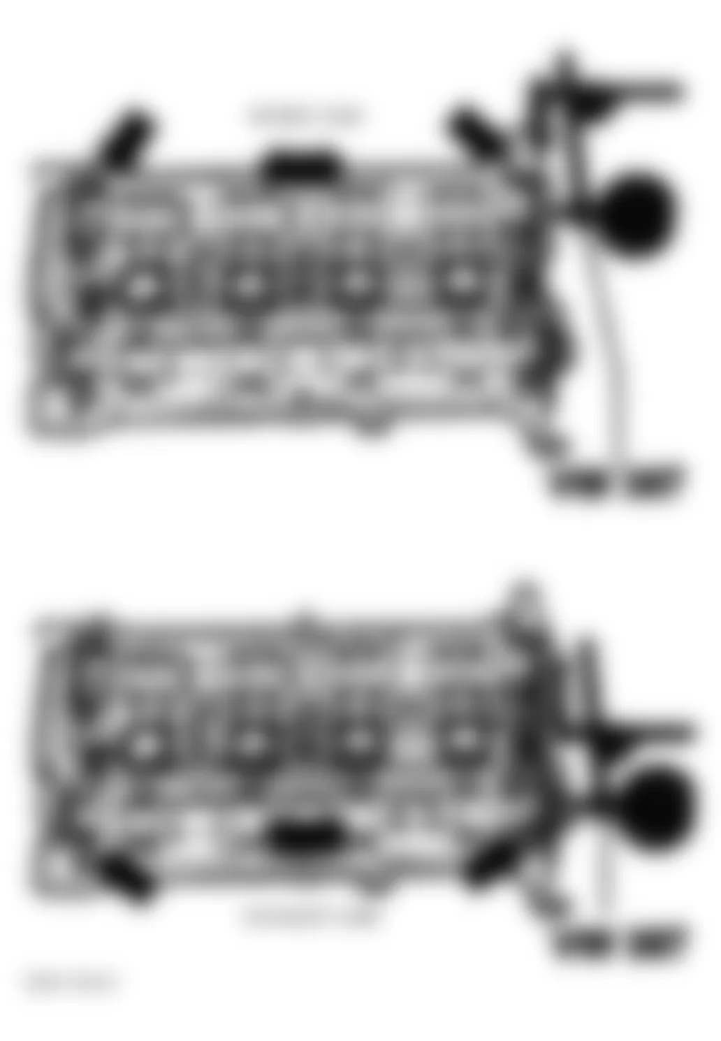
Fig. 128: Audi A4 1998 - Component Locations - Identifying Camshaft Bearing Caps
Audi A4 1998 - Camshaft Axial Play (Passat)
Measure camshaft axial play (intake and exhaust) with lifter and camshaft chain removed. Camshaft bearing caps No. 2. and No. 4. installed. Remove all other caps, note their locations for reassemble. See Fig. 128. Maximum wear limit .008" (.2 mm). See Fig. 129.
Fig. 129: Audi A4 1998 - Component Locations - Checking Camshaft Axial Play
Audi A4 1998 - Valves
CAUTION: Sodium-filled exhaust valves must not be disposed of until they have been properly treated as follows: By HAND (no air tools), saw the valves into two sections using a metal saw at a point between the center of the valve stem and the valve head. The valves must not come into contact with water when this is done. Throw the valves into a bucket of water (not more than ten at a time) and step back. A sudden chemical reaction will occur during which the sodium filling burns. After this treatment the valves can be disposed of as normal scrap.
Measure valve stem diameter and valve margin. If not within specification, replace valves. Replace as necessary. See VALVES & VALVE SPRINGS table under ENGINE SPECIFICATIONS.
Valves must not be refaced by grinding. Hand lap only. If lapping does not produce proper sealing, check valve seat. See VALVE SEATS.
Audi A4 1998 - Valve Springs
Information is not available from manufacturer.
Audi A4 1998 - CYLINDER BLOCK ASSEMBLY Piston & Rod Assembly
- Ensure piston, connecting rod and rod caps are marked with matching cylinder number prior to removal. Ensure engine front arrow is marked on top of piston and front mark "A" exists on rod and cap. See Fig. 130. Pistons and rods are to be replaced in sets of 4. Rod cap bolts and nuts must be replaced after removing or loosening.
Fig. 130: Audi A4 1998 - Component Locations - Assembling Piston & Rod - Mark piston in relation to pin. Remove circlips from ends of pin bore. Use Piston Pin Replacer/Installer (VW 222A) to remove and install piston pin. If pin is too tight, heat piston to 140? F (60? C). Ensure rod is properly positioned with piston. See Fig. 130.
Audi A4 1998 - Fitting Pistons
Measure clearances with cylinder block supported on work bench. Check clearance of piston-to-cylinder bore. Piston diameter is stamped on top of piston in millimeters. See PISTON-TO-CYLINDER BORE DIMENSIONS.
Audi A4 1998 PISTON-TO-CYLINDER BORE DIMENSIONS
Size Piston Diameter (1) Cylinder Bore Standard 3.187" (80.96 mm) 3.189" (81.01 mm) 1st Oversize 3.207" (81.46 mm) 3.209" (81.51 mm)
(1) Measurement does not include graphite coating, thickness of .02mm (.0008"). Graphite coating wears away.
Audi A4 1998 - Piston Rings
Install piston ring with TOP mark (if present) facing upward. Insert ring from bottom of cylinder block to a depth of about .591 (15 mm) and measure ring end gap. See Fig. 131. Measure ring side clearance with piston. See Fig. 132. If not within specification, replace as necessary. See PISTONS, PINS & RINGS table under ENGINE SPECIFICATIONS. Install rings on piston with TOP mark facing upward. Recessed edge on outside of center ring must face piston pin (down). Position ring gaps on piston at 120 degree intervals. See Fig. 130.
Fig. 131: Audi A4 1998 - Component Locations - Checking Piston Ring End Gap
Fig. 132: Audi A4 1998 - Component Locations - Checking Piston Ring Side Clearance
Audi A4 1998 - Rod Bearings
Mark rod caps for reinstallation. Use Plastigage to measure bearing oil clearance. DO NOT turn additional 90 degrees. Measure connecting rod side play. Replace or machine as necessary. See CRANKSHAFT, MAIN & CONNECTING ROD BEARINGS table under ENGINE SPECIFICATIONS. Lubricate bolt threads when installing connecting rod caps. Tighten evenly to specification in several steps. See TORQUE SPECIFICATIONS.
Audi A4 1998 - Crankshaft & Main Bearings
Main bearing caps are marked with matching journal for installation in original position. See Fig. 133. Use Plastigage? to measure oil clearance. Measure crankshaft end play. See Thrust Washer.
Fig. 133: Audi A4 1998 - Component Locations - Crankshaft Assembly
Audi A4 1998 - Thrust Washer
Insert feeler gauge between No. 3 main bearing and crankshaft thrust face to measure end play. Replace thrust washer as necessary. See CRANKSHAFT, MAIN & CONNECTING ROD BEARINGS table under ENGINE SPECIFICATIONS.
Audi A4 1998 - Cylinder Block
Measure cylinder bore diameter in 3 places: at center of bore and .39" (10 mm) from top and bottom of bore. See Fig. 134. If cylinder bore diameter is not within specification, hone cylinder bore until diameter meets first oversize specification. See CYLINDER BLOCK under ENGINE SPECIFICATIONS. When measuring cylinder bore, maximum allowable difference between actual measurement and standard specification is .0031" (.08 mm).
Fig. 134: Audi A4 1998 - Component Locations - Identifying Locations For Checking Cylinder Bore
Audi A4 1998 - ENGINE OILING ENGINE LUBRICATION SYSTEM Crankcase Capacity
See CRANKCASE CAPACITY table.
Audi A4 1998 CRANKCASE CAPACITY
Application Qts. (L) Without Filter Replacement 3.2 (3.0) With Filter Replacement 3.7 (3.5)
Audi A4 1998 - Oil Pressure
Check oil pressure with engine at normal operating temperature. Oil pressure at idle should be is 14-36 psi (1-2.5 bar) at 3000 RPM, 44-73 psi. (3-5 bar). At higher RPM oil pressure should not exceed 100 psi (7.0 bar). Inspect oil pump. See OIL PUMP.
Audi A4 1998 - OIL PUMP
NOTE: For help in identifying components and component locations, refer to illustration. See Fig. 135.
Audi A4 1998 - Removal & Installation
Remove oil pan. Remove oil pump attaching bolts and remove oil pump assembly. To install, reverse removal procedure.
Audi A4 1998 - Inspection
Check oil pump backlash and oil pump axial play. See Fig. 136 and Fig. 137 . If not within specification, replace oil pump assembly. See OIL PUMP SPECIFICATIONS table.
Fig. 135: Audi A4 1998 - Component Locations - Identifying Engine Oiling System Components
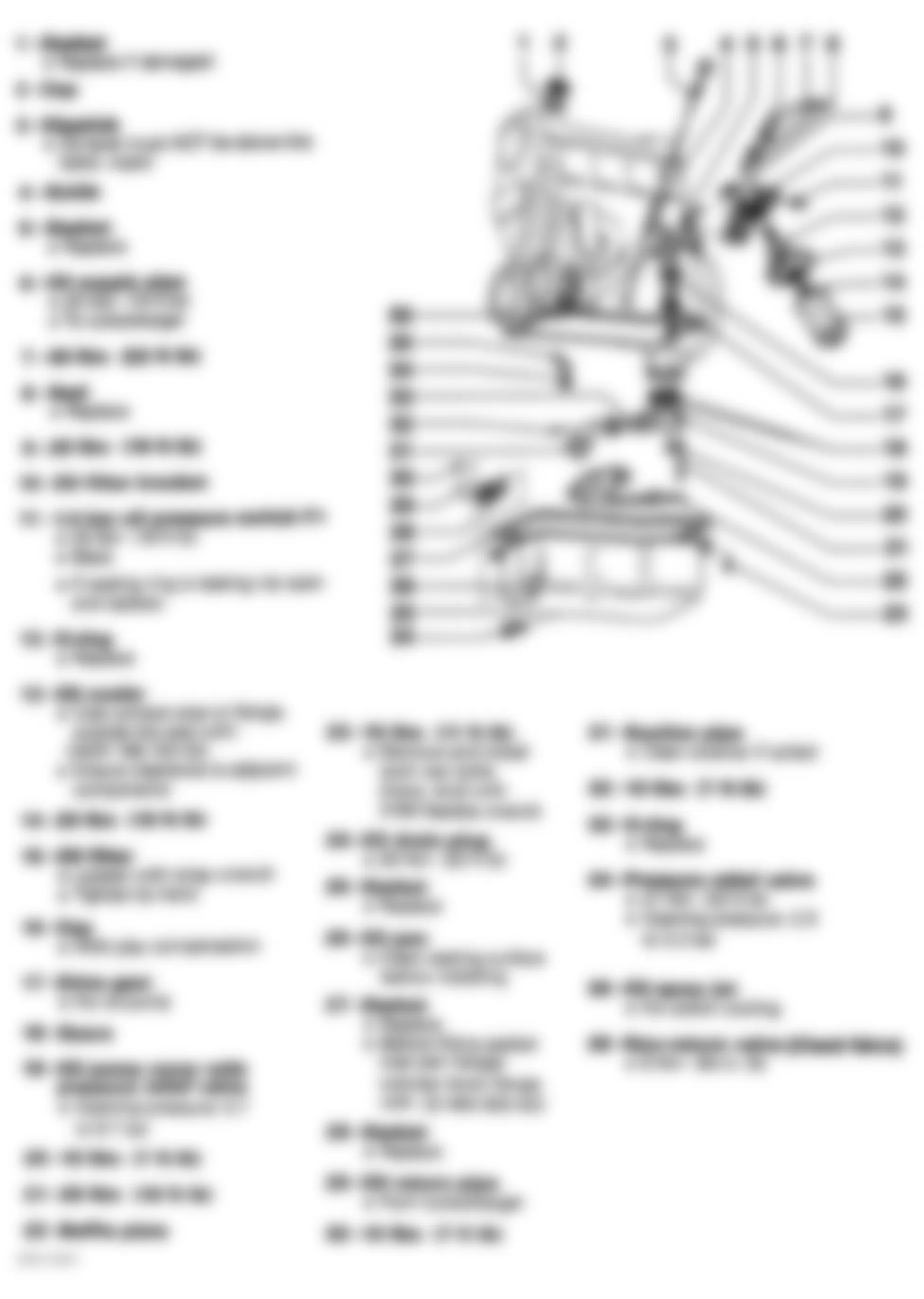
Fig. 136: Audi A4 1998 - Component Locations - Checking Oil Pump Gear Backlash
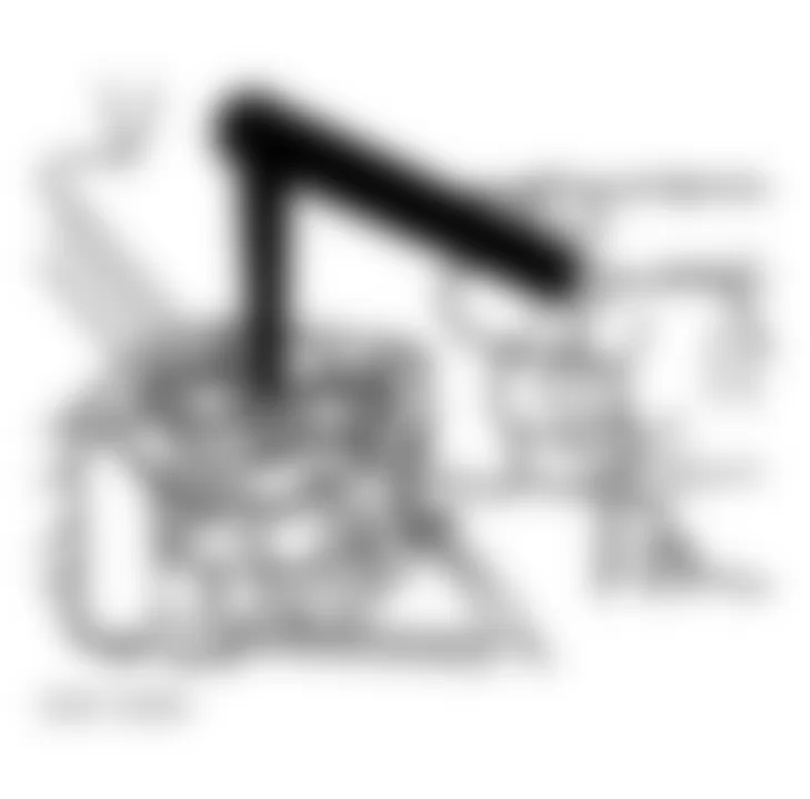
Fig. 137: Audi A4 1998 - Component Locations - Checking Oil Pump Axial Clearance
Audi A4 1998 OIL PUMP SPECIFICATIONS
Application In. (mm) Backlash New .002 (.05) Service Limit .008 (.20) Axial Play Limit .006 (.15)
Audi A4 1998 - TORQUE SPECIFICATIONS
Audi A4 1998 TORQUE SPECIFICATIONS
Application Ft. Lbs. (N.m) Camshaft Drive Gear Bolt 48 (65) Catalytic Converter-To-Turbocharger Bolt 30 (40) for FWD
22 (30) for AWD Catalytic Converter-To-Front Exhaust Pipe Bolt 18 (25) Connecting Rod Bearing Cap Nut (1) Step 1 22 (30) Step 2 Additional 90 Degrees Crankshaft Main Bearing Cap Bolt (1) Step 1 48 (65) Step 2 Additional 90 Degrees Crankshaft Timing Sprocket Bolt (1) Step 1 66 (90) Step 2 Additional 90 Degrees Cylinder Head Bolt (1) Step 1 44 (60) Step 2 Additional 90 Degrees Step 3 Additional 90 Degrees Driveplate (Flywheel) (1) Step 1 44 (60) Step 2 Additional 90 Degrees Engine Mount-To-Frame Bolt 18 (25) Engine Mount-To-Engine Support Bolt 18 (25) Engine-To-Torque Rod Bracket Bolt 18 (25) Exhaust Manifold-To-Cylinder Head Bolt & Nut 18 (25) Exhaust Pipe-To-Manifold Nut 30 (40) Intake Manifold Bracket Bolt 15 (20) Intermediate Shaft Sprocket Bolt 48 (65) Lock Carrier-To-Frame Bolt (A4) 33 (45) Lock Carrier-To-Frame Bolt (Passat) 37 (50) Oil Drain Plug 37 (50) Oil Pan-To-Engine Block Bolt (A4) M6 7 (10) M10 33 (45) Oil Pan-To-Engine Block Bolt (Passat) 11 (15) Oil Pan-To-Transmision Bolt 33 (45) Oil Pump Cover Long Bolt 18 (25) Oil Pump Cover Short Bolt (2) Oil Pan Drain Plug 37 (50) Piston Oil Pressure Relief Valve 20 (27) Pressure Plate-To-Flywheel Bolt (1) Step 1 44 (60) Step 2 Additional 90 Degrees Sender Wheel (Sensor Trigger) Step 1 7 (10 Nm) Step 2 Additional 90 Degrees Starter Mount Bolt 48 (65) Timing Belt Tensioner Nut 18 (25) Transmission Mount-To-Frame Bolt (M8) 15 (20) Transmission Support-To-Mount Bolt (M10) 33 (45) Water Pump-To-Housing Bolt 18 (25) INCH Lbs. (N.m) Camshaft Bearing Cap Bolt 89 (10) Lock Carrier-To-Fender Torx Bolt (A4) 89 (10) Lock Carrier-To-Fender Torx Bolt (Passat) 71 (8) Transaxle/Engine Cover Plate Bolt 89 (10) Valve Cover Retaining Nut 89 (10) Water Pump Nut 89 (10)
(1) Use NEW bolts.
(2) Tighten bolt to 89 INCH lbs. (10 N.m).
Audi A4 1998 - ENGINE SPECIFICATIONS GENERAL SPECIFICATIONS
Audi A4 1998 GENERAL SPECIFICATIONS
Application Specification Displacement 110 Cu. In. (1.8L) Bore 3.189 (81.01) Stroke 3.40" (86.4 mm) Compression Ratio 9.5:1 Fuel System Motronic SFI
Audi A4 1998 - CRANKSHAFT, MAIN & CONNECTING ROD BEARINGS
Audi A4 1998 CRANKSHAFT, MAIN & CONNECTING ROD BEARINGS
Application In. (mm) Crankshaft End Play Standard .003-.009 (.07-.23) Service Limit .011 (.30) Main Bearings Journal Diameter Standard Nominal 2.1260 (54.000) Maximum 2.1268 (54.022) Minimum 2.1243 (53.958) 1st Undersize Nominal 2.1161 (53.750) Maximum 2.1170 (53.772) Minimum 2.1145 (53.708) 2nd Undersize Nominal 2.1063 (53.500) Maximum 2.1071 (53.522) Minimum 2.1046 (53.458) 3rd Undersize Nominal 2.0965 (53.250) Maximum 2.0973 (53.272) Minimum 2.0948 (53.208) Journal Out-Of-Round (1) Journal Taper (1) Oil Clearance Standard .0008-.0024 (.020-.060) Service Limit .005 (.15) Connecting Rod Bearings Journal Diameter Standard Nominal 1.8819 (47.800) Maximum 1.8828 (47.823) Minimum 1.8802 (47.758) 1st Undersize Nominal 1.8720 (47.550) Maximum 1.8729 (47.572) Minimum 1.8704 (47.508) 2nd Undersize Nominal 1.8622 (47.300) Maximum 1.8631 (47.323) Minimum 1.8605 (47.258) 3rd Undersize Nominal 1.8524 (47.051) Maximum 1.8532 (47.074) Minimum 1.8507 (47.008) Journal Out-Of-Round (1) Journal Taper (1) Oil Clearance Standard .002-.012 (.05-.31) Service Limit .015 (.37)
(1) Information is not available from manufacturer.
Audi A4 1998 - CONNECTING RODS
Audi A4 1998 CONNECTING RODS
Application In. (mm) Bore Diameter Pin Bore (1) Crankpin Bore (1) Center-To-Center Length (1) Side Play Standard .002-.012 (.05-.31) Service Limit .015 (.37)
(1) Information is not available from manufacturer.
Audi A4 1998 - PISTONS, PINS & RINGS
Audi A4 1998 PISTONS, PINS & RINGS
Application In. (mm) Pistons Clearance .0017 (.045) Standard Diameter 3.187 (80.96) 1st Oversize 3.207 (81.46) Pins Diameter (1) Piston Fit (1) Rod Fit (1) Rings No. 1 & 2 End Gap Standard .007-.016 (.20-.40) Service Limit .031 (.80) Side Clearance Standard .002-.003 (.06-.09) Service Limit .007 (.20) No. 3 (Oil) End Gap Standard .010-.020 (.25-.51) Service Limit .031 (.80) Side Clearance Standard .001-.002 (.03-.06) Service Limit .006 (.15)
(1) Information is not available from manufacturer.
Audi A4 1998 - CYLINDER BLOCK
Audi A4 1998 CYLINDER BLOCK
Application In. (mm) Cylinder Bore Standard Diameter 3.189 (81.01) 1st Oversize 3.209 (81.51) Maximum Taper .003 (.08)
Audi A4 1998 - VALVES & VALVE SPRINGS
Audi A4 1998 VALVES & VALVE SPRINGS
Application Specification Intake Valves Face Angle 45? Head Diameter 1.059" (26.9 mm) Length 4.127-4.147" (104.84-105.34 mm) Minimum Margin (1) Stem Diameter .234" (5.96 mm) Valve Stem Installed Height (Minimum) Center 1.32 (33.7) Outer 1.29 (34.0) Exhaust Valves Face Angle 45? Head Diameter 1.177" (29.9 mm) Length 4.080-4.100" (103.64-104.14 mm) Minimum Margin (1) Stem Diameter .233" (5.94 mm) Valve Stem Installed Height (Minimum) 1.35 (34.4)
(1) DO NOT machine valves; hand lap only.
Audi A4 1998 - CYLINDER HEAD
Audi A4 1998 CYLINDER HEAD
Application Specification Cylinder Head Height (Minimum) 5.480" (139.2 mm) Maximum Warpage .004" (.10 mm) Valve Seats Intake Valve Seat Angle 45? Seat Width .059-070" (1.50-1.80 mm) Exhaust Valve Seat Angle 45? Seat Width .070" (1.80 mm) Valve Guides Intake Valve Valve Guide Installed Height (1) Valve Stem-To-Guide Oil Clearance (2) .031" (.80 mm) Exhaust Valve Valve Guide Installed Height (1) Valve Stem-to-Guide Oil Clearance (2) .031" (.80 mm)
(1) Valve guide shoulder flush with cylinder head.
(2) New valve installed in cylinder head. Dial indicator used to measure valve wobble in guide.
Audi A4 1998 - CAMSHAFT
Audi A4 1998 CAMSHAFT
Application In. (mm) Journal Diameter Standard (1) Undersize (1) End Play .007 (.20) Runout .0004 (.010) Oil Clearance (Maximum) .004 (.10)
(1) Information is not available from manufacturer.