Audi A4 2001 - 2001 ELECTRICAL Fuses & Circuit Breakers - A4, A4 Quattro, A4 Avant Quattro, S4, S4 Quattro, S4 Avant Quattro
Audi A4 2001 - FUSES
| NOTE: | Information in this article applies to the 2002 S4, S4 Avant Quattro and S4 Quattro. |
Audi A4 2001 - FUSE PANEL LOCATION
Fuse panel is located behind left side of dashboard. See Fig. 1.

Fig. 1: Audi A4 2001 - Component Locations - Locating Fuse Panel
Audi A4 2001 - FUSE COLOR IDENTIFICATION
Audi A4 2001 FUSE COLOR/AMP RATING
| Fuse Color | Amp Rating |
| Blue | 15 |
| Brown | 7.5 |
| Green | 30 |
| Light Brown | 5 |
| Lilac | 3 |
| Red | 10 |
| Transparent (White) | 25 |
| Yellow | 20 |
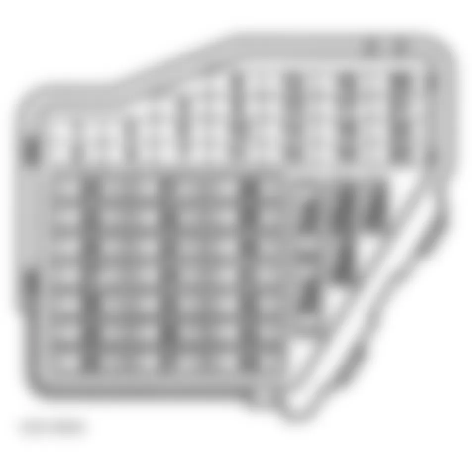
Audi A4 2001 - FUSE PANEL IDENTIFICATION
For fuse position within panel, see Fig. 2. For fuse position number, amp rating and description of circuits protected, see FUSE IDENTIFICATION table.
Fig. 2: Audi A4 2001 - Component Locations - Identifying Fuse Panel Fuses
| NOTE: | Fuses 23 through 44 may be designated in wiring diagrams with a prefix of 2. For example, fuse No. 29 may be labeled as 229. Fuse No. 43 may be labeled as 243. |
Audi A4 2001 FUSE IDENTIFICATION (FUSE PANEL)
| Fuse No. | Amp Rating | Circuits Protected |
| 1 | 5 | Washer Nozzle Heaters |
| 2 (1) | 5 | Emergency Flasher Relay |
| 3 | 5 | Glove Compartment Light, A/C Control Head |
| 4 | 5 | License Plate Light |
| 5 (1) | 10 | Oil Level Thermal Sensor, Fog Light Control Module (Front & Rear), Mirror Adjustment Switch, A/C Control Head, Radio, Rear Lamp Control Module, Heated Seats Adjuster, Navigation With CD-Mechanism Control Module, Telephone Receiver |
| 6 (1) | 5 | Central Locking, Alarm System, Interior Light Delay Control Module, Door Lock Switch |
| 7 (1) |
| ATQ & APB | 10 | Brake Light Switch, Clutch Vacuum Vent Valve Switch (2), Anti Slip Control Switch |
| AWM | 10 | Brake Light Switch, Anti Slip Control Switch |
| 8 (1) | 5 | Telephone Receiver |
| 9 | 10 | Heated Mirror (Driver's & Passenger's) |
| 10 | 10 | Headlight Beam Adjusting Motors, Headlight Range Control Module |
| 11 | N/A | Vacant |
| 12 (3) | 10 | Data Link Connector |
| 13 | 10 | Brake Light Switch |
| 14 (3) | 10 | Central Locking, Alarm System, Interior Light Delay Control Module, Door Warning Lights Control Module, Vanity Mirrors Light Switch |
| 15 (3) | 10 | Instrument Cluster Combination Processor |
| 16 | 5 | Steering Angle Sensor Control Module (Left) |
| 17 | 10 | Heated Door Lock |
| 18 | 10 | Headlight High Beam Indicator Light, High Beam Headlight (Right) |
| 19 | 5 | Park Light Switch, High Beam Headlight (Left) |
| 20 | 10 | Headlight Dimmer/Flasher Switch, Front Lamp Control Module |
| 21 | 10 | Headlight Dimmer/Flasher Switch Front Lamp Control Module |
| 22 | 5 | Parking Light (Right), Tail Light (Right), Front Lamp Control Module |
| 23 | 5 | Parking Light (Left), Tail Light (Left), Park Light Switch, Front Lamp Control Module |
| 24 | 25 | Windshield Wiper Intermittent Switch, Washer/Wiper Intermittent Relay |
| 25 | 30 | A/C Control Head, A/C Pressure Switch, A/C Clutch Relay, Fresh Air Blower |
| 26 | 30 | Rear Window Defogger Switch |
| 27 | 15 | Rear Window Wiper Motor, Air Bag |
| 28 |
| ATQ & APB | 20 | Fuel Pump |
| AWM | 15 | Fuel Pump |
| 29 |
| ATQ | 20 | Power Output Stage, Distributor Ignition Capacitor |
| APB | 20 | Leak Detection Pump, Ignition Coils |
| AWM | 20 | Ignition Coils, Motronic Engine Control Module |
| 30 | 20 | Power Sunroof Control Module |
| 31 |
| ATQ | 15 | Back-Up Light Switch, Motronic Engine Control Module, Data Link Connector, Mass Air Flow Sensor, Automatic Day/Night Interior Mirror, Garage Door Opener, (4) |
| ATM & AWM | 15 | Back-Up Light Switch, Data Link Connector, Mass Air Flow Sensor, Automatic Day/Night Interior Mirror, Garage Door Opener, (4) |
| 32 |
| ATQ & APB | 20 | Fuel Injectors, Cruise Control Switch, Motronic Engine Control Module |
| AWM | 20 | Fuel Injectors |
| 33 | 15 | Cigarette Lighter |
| 34 |
| ATQ & AWM | 15 | Motronic Engine Control Module, Leak Detection Pump |
| APB | 15 | Motronic Engine Control Module |
| 35 | N/A | Vacant |
| 36 | 15 | Foglight Control Module (Front & Rear) |
| 37 | 20 | Radio, Speakers |
| 38 (3) | 15 | Central Locking, Alarm System, Interior Light Delay Control Module, Luggage Compartment Light, Trunk Lid Alarm Switch |
| 39 (3) | 15 | Emergency Flasher Switch |
| 40 | 25 | Horn |
| 41 | 25 | ABS Solenoid Valve |
| 42 | 25 | ABS Control Module |
| 43 | N/A | Vacant |
| 44 (3) | 15 | Heated Seat Adjuster (Driver's & Passenger's) |
| (2) | Manual transmission only. | | (4) | On vehicles equipped with Tiptronic transmission, the above circuits are protected, including the multi-function transmission range switch and shift lock solenoid. | |
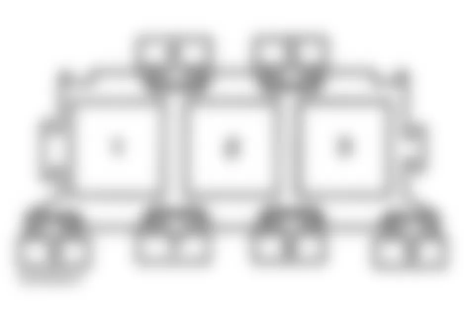
Audi A4 2001 - RELAYS THREE-WAY RELAY CARRIER
For fuse and relay positions within carrier, see Fig. 3. For relay number, position number and circuits protected, see THREE-WAY RELAY IDENTIFICATION table.
| NOTE: | Three-way relay carrier is within E-box, in left rear corner of engine compartment. |
Fig. 3: Audi A4 2001 - Component Locations - Identifying Three-Way Relay Carrier Relays
Audi A4 2001 RELAY IDENTIFICATION (THREE-WAY RELAY CARRIER)
| Position | Relay No. | Circuit Protected |
| 1 | N/A | Not Used |
| 2 | J316 | Secondary Air Injector (AIR) |
| 3 (1) | J271 | Motronic Engine Control Module Power Supply |
| (1) | Applies to engine model AWM only. | |
Audi A4 2001 FUSE IDENTIFICATION (THREE-WAY RELAY CARRIER)
| Position No. | Fuse No. | Amp Rating | Circuit Protected |
| 4 | N/A | N/A | Not Used |
| 5 (1) | S204 | 15 | Camshaft Adjustment Valve |
| 6 | N/A | N/A | Not Used |
| 7 | S130 | 40 | Secondary Air Pump |
| 8 | N/A | N/A | Not Used |
| 9 | N/A | N/A | Not Used |
| (1) | Applies to engine models with 1.8L Turbo (AWM engine code) only. | |
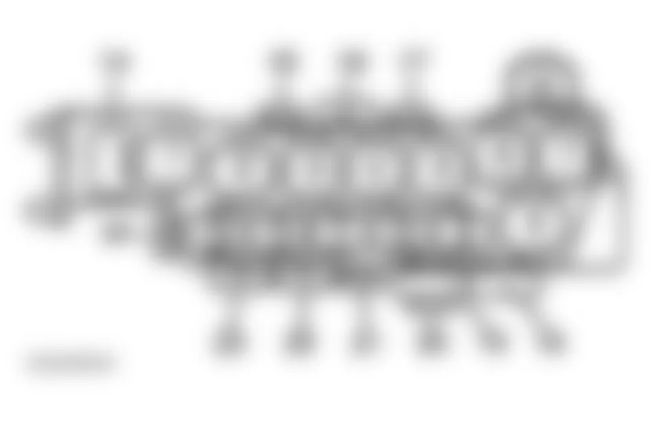
Audi A4 2001 - EIGHT-WAY RELAY CARRIER
For fuse and relay positions within carrier, see Fig. 4. For relay number, position number and circuits protected, see EIGHT-WAY RELAY IDENTIFICATION table. For fuse number, amp rating number position and description of circuits protected, see FUSE IDENTIFICATION table.
| NOTE: | Eight-way relay carrier is located in driver's side footwell, behind trim panel. |
Fig. 4: Audi A4 2001 - Component Locations - Identifying Eight-Way Relay Carrier Relays
Audi A4 2001 RELAY IDENTIFICATION (EIGHT-WAY RELAY CARRIER)(2)
| Position No. | Relay No. | Circuit Protected |
| 1 (1) | J26 | Coolant Fan Control |
| 2 | J101 | Second Speed Coolant fan Control |
| 3 | J26 | Coolant Fan Control |
| 4 | J106 | ABS Solenoid Valve |
| 5 | J452 | Door Warning Lights Control Module |
| 6 | N/A | Not Used |
| 7 | J185 | ABS Hydraulic Pump |
| 8 | N/A | Vacant |
| (1) | Applies to vehicles equipped with 1.8L Motronic engine only. | | (2) | Positions 9-14 manufacturer left intentionally blank. | |
Audi A4 2001 FUSE IDENTIFICATION (EIGHT-WAY RELAY CARRIER)
| Position No. | Fuse No. | Amp Rating | Circuit Protected |
| 15 | S80 | 30 | Power Seat Circuit Breaker (Memory) |
| 16 | S44 | 30 | Power Seat Circuit Breaker |
| 17 | N/A | N/A | Not Used |
| 18 | S53 | 60 | ABS Hydraulic Pump |
| 19 | S42 | 40 | Coolant Fan |
| 20 | N/A | N/A | Not Used |
| 21 |
| A4 | S51 | 5 | Radiator Fan Relay Coil |
| S4 | S198 | 5 | Coolant Fan |
| 22 (1) | S43 | 30 (2) | Power Window (Rear) |
| 23 | S37 | 30 | Power Window (Front) |
| 24 | S184 | 30 | Socket Fuse |
| (1) | On vehicle equipped with 1.8L Motronic engine, fuse is labeled as S42, with an amp rating of 40 and protects coolant fan control and second speed coolant fan control. | | (2) | On S4 model equipped with Motronic engine, amp rating is 60. | |
Audi A4 2001 - THIRTEEN-WAY RELAY CARRIER
For relay position within carrier, see Fig. 5. For relay number, position number and circuits protected, see THIRTEEN-WAY RELAY CARRIER IDENTIFICATION table.
| NOTE: | Thirteen-way relay carrier is located in driver's side footwell, behind trim panel. |
Fig. 5: Audi A4 2001 - Component Locations - Identifying Thirteen-Way Relay Carrier Relays
Audi A4 2001 RELAY IDENTIFICATION (THIRTEEN-WAY RELAY CARRIER)
| Position No. | Relay No. | Circuit Protected |
| 1 | N/A | Not Used |
| 2 | J453 | Multi-Function Steering Wheel Control Module |
| 3 | J453 | Multi-Function Steering Wheel Control Module |
| 4 | J124 | Lamp Control Module (Front & Rear) |
| 5 | J124 | Lamp Control Module (Front & Rear) |
| 6 | N/A | Not Used |
| 7 | N/A | Not Used |
| 8 | N/A | Not Used |
| 9 | N/A | Not Used |
| 10 (1) | J569 | Brake Booster Relay |
| 11 | N/A | Not Used |
| 12 | N/A | Not Used |
| 13 (2) | J433 | Starter Locking Relay |
| (3) | J44 | A/C Clutch |
| (1) | Applies to 2.8L V6 (ATQ engine code) and 1.8L Turbo (AWM engine code) only. | | (2) | Relay number is also referred to as J226, and protects park/neutral position. | | (3) | Relay is installed in any free position, and is not allocated any specific position within thirteen-way relay carrier. | |
Audi A4 2001 FUSE IDENTIFICATION (THIRTEEN-WAY RELAY CARRIER)
| Position No. | Fuse No. | Amp Rating | Circuit Protected |
| 14 | N/A | N/A | Not Used |
| 15 | N/A | N/A | Not Used |
| 16 | N/A | N/A | Not Used |
| 17 |
| ATQ | S204 | 15 | Brake Booster Vacuum Pump |
| AWM | S205 | 15 | Brake Booster Vacuum Pump |
| 18 | N/A | N/A | Not Used |
Audi A4 2001 - MICRO CENTRAL ELECTRIC PANEL
For relay position within panel, see Fig. 6. For relay number, position number and circuits protected, see MICRO CENTRAL ELECTRIC IDENTIFICATION table.
| NOTE: | Micro central electric panel is located in driver's side footwell, behind trim panel. |
Fig. 6: Audi A4 2001 - Component Locations - Identifying Micro Central Electric Relays
Audi A4 2001 MICRO CENTRAL ELECTRIC IDENTIFICATION
| Position No. | Relay No. | Circuit Protected |
| 1 | J4 | Dual Horn |
| 2 | J59 | Load Reduction |
| 3 | N/A | Not Used |
| 4 | J17 | Fuel Pump |
| 5 | J31 | Washer/Wiper Intermittent Relay |
| 6 | J31 | Washer/Wiper Intermittent Relay |