
Audi A5 Quattro 2009 - 2008-10 ELECTRICAL Fuses & Circuit Breakers - A5 & S5
Audi A5 Quattro 2009 - IDENTIFICATION
WARNING: Vehicles are equipped with air bag supplemental restraint system. Before attempting any repairs involving steering column, instrument panel or related components, see AIRBAG SAFETY PRECAUTIONS in BODY INTERIOR article.
Audi A5 Quattro 2009 - ENGINE CODE
Engines are identified by a 4 letter code stamped onto the engine block, for engine identification see engine code on the vehicle data plate.
Engine Displacement Engine Stamp Code 3.2L CALA 4.2L CAUA
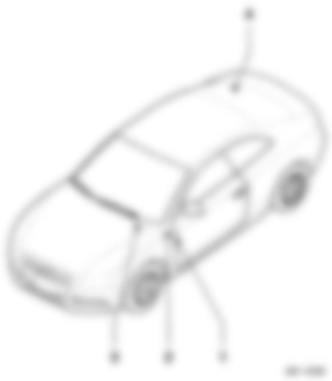
Audi A5 Quattro 2009 - COMPONENT LOCATION FUSES Relay & Fuse Holder Panel Locations
NOTE: For relay identification within the relay and fuse holder panels, refer to RELAY LOCATIONS under relays.

Location No. Description Refer To 1 Fuse Panel A -SA- Fig. 2 2 Relay / Fuse Panel B -SB- Fig. 3 3 Fuse Panel C -SC- Fig. 4 (1)
Fig. 5 (2) 4 Relay /Fuse Panel with Vehicle Electrical System Control Module -J519- Fig. 12 5 6-Pin connector station A-pillar, driver's side Fig. 10 6 3-Pin Relay /Fuse Panel Fig. 9 7 6-Pin connector station A-pillar, front passenger's side Fig. 11 8 Fuse Panel D -SD- Fig. 6 9 Terminal 30 Wire Junction 2 -TV22- With Battery Jump Start Terminal -U3- Fig. 8 10 Relay /Fuse Panel F -SF- Fig. 7 (3)
(1) Illustration represent m.y. 2008-09.
(2) Illustration represent m.y. 2010.
(3) Illustration represent m.y. 2008-10, callouts differ between 2008/09 and 2010 relay/fuse panels.
Fig. 2: Audi A5 Quattro 2009 - Component Locations - Fuse Panel A -SA-
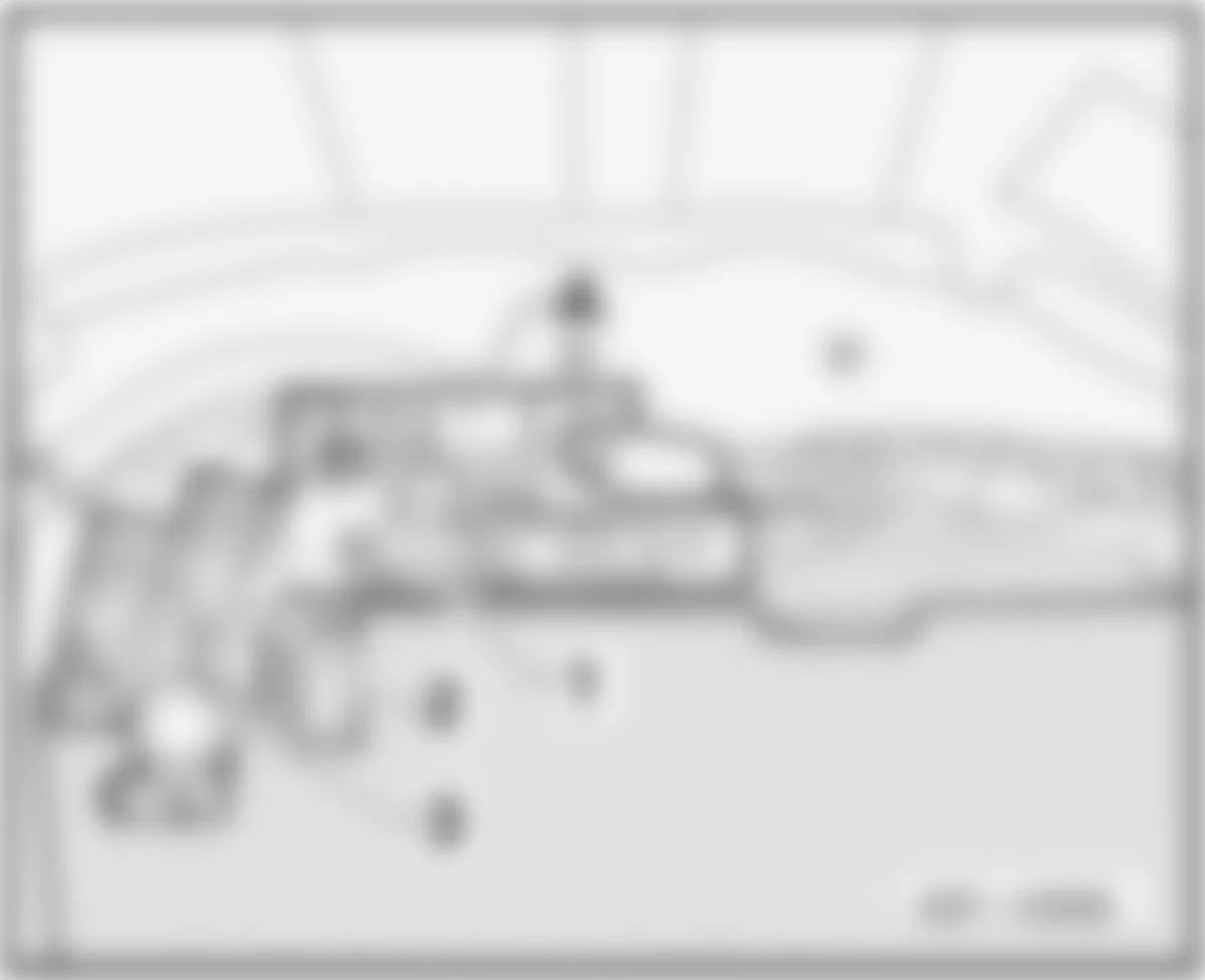
Fig. 3: Audi A5 Quattro 2009 - Component Locations - Relay / Fuse Panel B -SB-

Fig. 4: Audi A5 Quattro 2009 - Component Locations - Fuse Panel C -SC- (M.Y. 2008-09)

Fig. 5: Audi A5 Quattro 2009 - Component Locations - Fuse Panel C -SC- (M.Y. 2010)

Fig. 6: Audi A5 Quattro 2009 - Component Locations - Fuse Panel D -SD-

Fig. 7: Audi A5 Quattro 2009 - Component Locations - Relay / Fuse Panel F -SF-


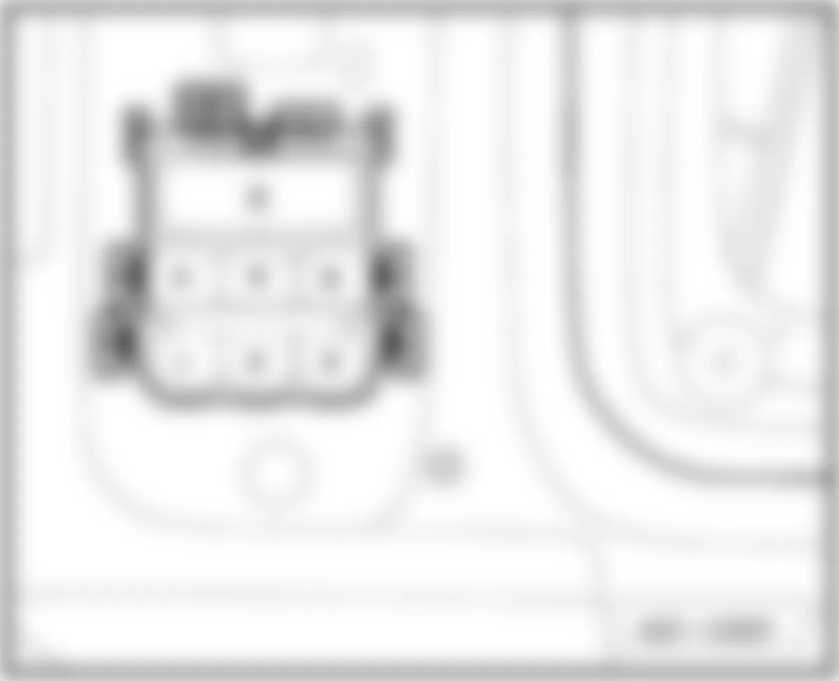
Fig. 9: Audi A5 Quattro 2009 - Component Locations - 3-Pin Relay /Fuse Panel


Audi A5 Quattro 2009 - RELAYS Relay Locations
NOTE: For fuse identification within the relay and fuse holder panels, refer to RELAY & FUSE HOLDER PANEL LOCATIONS under fuses.
Location No. Description Refer To 1 Relay / Fuse Panel with Vehicle Electrical System Control Module -J519-
Component: -J329-, -J413-, -J910-Fig. 12 2 3-Pin Relay / Fuse Panel
Component: -J359-, -J360-Fig. 9 3 Relay / Fuse Panel B -SB-
Component: -J17-, -J53-, -J151-, -J179-, -J271-, -J299-, -J317-, -J496-, -J569-, -J695-Fig. 21 4 Relay / Fuse Panel F -SF-
Component: -J9-, -J807-Fig. 7
Audi A5 Quattro 2009 - COMPONENT IDENTIFICATION FUSES - CIRCUIT PROTECTION
WARNING: Never replace a fuse with one that has a higher amperage rating. A fuse with a too high amperage could damage the electrical part and cause a fire.
For access to fuse boxes, refer to illustrations below.


The individual circuits are protected by fuses. The fuse panels with the fuses are located on the left and right front faces of the instrument panel behind a cover and in the right storage area in the luggage compartment.
There is a plastic clip (fuse puller 'A') in the cover on the left side of the instrument panel, which can be used to remove the fuses. The crank (B) is used for emergency operation of the power roof (if equipped). You will also find a label (C) on both end covers of the instrument panel with the fuse layout) for the corresponding fuse panel. - Fig. 15.
Two spare fuses and a sticker identifying the fuses are located on the inside of the fuse box cover.
Fuses with the proper ampere ratings are available at your Audi dealer.
NOTE:
AUTOMATIC CIRCUIT BREAKERS:
The electric seat adjusters are protected with circuit breakers which reset automatically after the circuit overload has been corrected.
Audi A5 Quattro 2009 - Fuse - Color Codes
Identifying fuse color and ampere rating, refer to table below.
WARNING: Never replace a fuse with one that has a higher amperage rating. A fuse with a too high amperage could damage the electrical part and cause a fire.
Audi A5 Quattro 2009 IDENTIFYING FUSE BY COLOR
Current Rating Amperes Color 1A Black 3A Violet 5A Light Brown 7.5A Brown 10A Red 15A Blue 20A Yellow 25A White or Natural 30A Green 35A Green-Blue 40A Orange 50A Red
Audi A5 Quattro 2009 - Replacing A Fuse
A problem in the electrical system may be caused by a blown fuse.
- Switch off the ignition and the electrical component affected.
- Carefully pry the face cover off the instrument panel using the ignition key or a screwdriver. See Fig. 14.
- Check the fuse index to find out which fuse belongs to the component which has failed. See FUSE INDEX INFORMATION.
- Remove the blown fuse with the plastic clip provided. The clip is located on the holder in the fuse box cover.
- Replace a blown fuse (recognizable by the melted metal strip inside) with a fuse of the same amperage.
- Firmly snap the cover back onto the instrument panel face.
Audi A5 Quattro 2009 - FUSE INDEX INFORMATION 1.2- FUSE PANEL A -SA- CENTER OF TRUNK (BATTERY)
NOTE: The fuse panel A -SA- is located on battery positive terminal in luggage compartment. The battery is located in the center of the trunk in the well area under the trim, refer to illustrations below.
For fuse identification and amperage rating refer to FUSE - COLOR CODES.
Fig. 19: Audi A5 Quattro 2009 - Component Locations - Fuse Panel A -SA-

Fig. 20: Audi A5 Quattro 2009 - Component Locations - Identifying Location Of Battery

1.2.1 - FUSES:
Audi A5 Quattro 2009 IDENTIFYING FUSES (FUSE PANEL A -SA- CENTER OF TRUNK)
Location/
PositionRating (A) Function/Component Wiring
IDTerminal A - Battery Interrupt Igniter -N253- - - 1 110A Vehicle Electrical System Supply
Engine Component SupplySA1 30 2 110A Vehicle Electrical System Supply
Engine Component SupplySA2 30 3 40A Driving School Option SA3 30 3 50A Rental Car Option SA3 30 3 110A Council Car Option SA3 30 3 80A (1) ABS Control Module Fuse 1 -S123- (1)
ABS Control Module Fuse 2 -S124- (1)
ABS Control Module Fuse 3 -S137- (1)SA3 30
(1) Only models with right-hand drive.
NOTE: Whenever replacing a fuse, always consult the sticker on the inside of the fuse panel cover. It contains the most up-to-date information regarding the fuse arrangement.
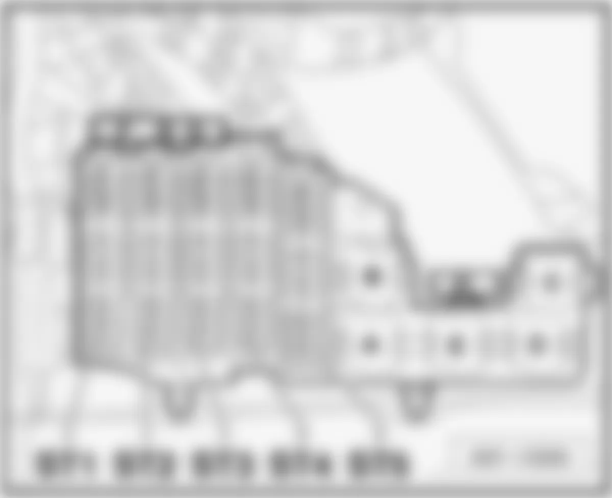
Audi A5 Quattro 2009 - 1.3- RELAY / FUSE PANEL B -SB- IN E-BOX PLENUM CHAMBER
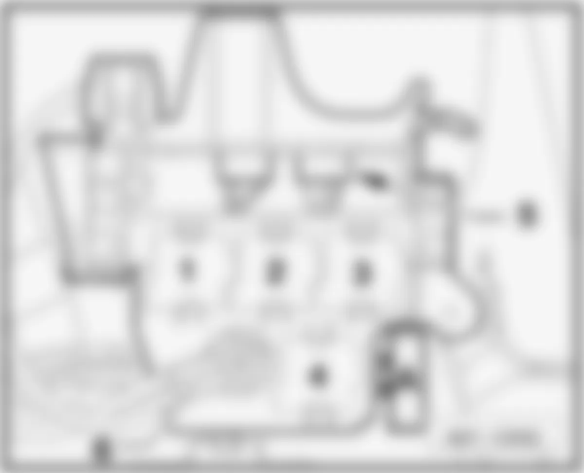
NOTE: The relay and fuse panel B -SB- is located in electronic box on left side of the engine compartment in plenum chamber, refer to illustration below. For relay identification related to relay and fuse panel B -SB- refer to RELAY AND FUSE HOLDER IN E-BOX PLENUM CHAMBER under relays.
For fuse identification and amperage rating refer to FUSE - COLOR CODES.
Fig. 21: Audi A5 Quattro 2009 - Component Locations - Relay / Fuse Panel B -SB-

1.3.1 - SINGLE FUSES:
Audi A5 Quattro 2009 IDENTIFYING SINGLE FUSES (RELAY & FUSE PANEL IN E-BOX PLENUM CHAMBER)
Location Rating (A) Function/Component K 60A Strip fuse for engine glow plugs -S39- (1) K 80A Strip fuse for engine glow plugs -S39- (2) K 50A Secondary Air Injection (AIR) Pump Fuse -S130- (3),(4) L 15A Brake System Vacuum Pump Fuse -S283- (4) ST1 - Fuse Carrier 1, Fuses (5)
(1) Only models with 4 cylinder diesel engine.
(2) Only models with 6 cylinder diesel engine.
(3) Only models with 6 cylinder gasoline engine.
(4) Only models with 8 cylinder gasoline engine.
(5) - the fuse carrier ST1 (Black) table.
1.3.2 - FUSES IN FUSE CARRIER ST1 (BLACK):
Audi A5 Quattro 2009 IDENTIFYING FUSES IN CARRIER ST1 (IN E-BOX PLENUM CHAMBER - ST1 BLACK)
Fuse
No.Rating
(Amperage)Function/Component Wiring
ID.Terminal 1 15A Transmission Control Module (TCM) -J217-
Direct Shift Gearbox (DSG) Mechatronic -J743-SB1 30 2 5A Oil Level Thermal Sensor -G266- SB2 87 3 5A Engine Control Module (ECM) -J623-
Mass Air Flow (MAF) Sensor -G70- (1) (2)SB3 15 4 5A Engine Control Module (ECM) -J623- SB4 30 5 10A (2)
15A (3)
15A (4)
15A (5)
15A (6)
15A (7)
20A (1)Mass Air Flow (MAF) Sensor -G70- (5)
Automatic Glow Time Control Module -J179- (6) (7)
Secondary Air Injection (AIR) Pump Relay -J299- (4) (5)
Throttle Valve Control Module -J338- (7)
Preheating Coolant, Low Heat Output Relay -J359- (6) (7)
Preheating Coolant, High Heat Output Relay -J360-(6) (7)
Wastegate Bypass Regulator Valve -N75- (6)
Positive Crankcase Ventilation (PCV) Heating Element -N79- (6)
Evaporative Emission (EVAP) Canister Purge Regulator Valve 1 -N80- (4) (5)
Secondary Air Injection (AIR) Solenoid Valve -N112- (4)
Left electrohydraulic engine mounting regulator valve -N144- (5) (6) (7)
Right electrohydraulic engine mounting regulator valve -N145- (5) (7)
Intake Manifold Tuning (IMT) Valve -N156-(4)
Air filter bypass flap valve -N275- (6) (7)
Fuel Pressure Regulator Valve -N276-(1) (2)
Fuel Metering Valve -N290- (4) (5)
Secondary Air Injection (AIR) Solenoid Valve 2 -N320-(4)
Intake Manifold Change-Over Valve -N335- (5)
Exhaust Gas Recirculation (EGR) Cooler Switch-Over Valve -N345-(6) (7)
Fuel Metering Valve 2 -N402- (5)
Oil Pressure Regulation Valve -N428- (4) (7)
Leak Detection Pump (LDP) -V144- (4) (5)SB5 87 6 15A Engine Control Module (ECM) -J623- SC6 87 7 10A (1)
10A (3)
10A (5)
10A (6)
10A (7)
15A (2)
15A (4)Map Controlled Engine Cooling Thermostat -F265- (5)
Actuator 1 for camshaft adjustment -F366- (2) (4)
Actuator 2 for camshaft adjustment -F367- (2) (4)
Actuator 3 for camshaft adjustment -F368- (2) (4)
Actuator 4 for camshaft adjustment -F369- (2) (4)
Actuator 5 for camshaft adjustment -F6370- (2) (4)
Actuator 6 for camshaft adjustment -P371- (2) (4)
Actuator 7 for camshaft adjustment -P372-(2) (4)
Actuator 8 for camshaft adjustment -F373- (2) (4)
Actuator 9 for camshaft adjustment -F374- (4)
Actuator 10 for camshaft adjustment -F375- (4)
Actuator 11 for camshaft adjustment -F376- (4)
Actuator 12 for camshaft adjustment -F377- (4)
Coolant Circulation Pump Relay -J151- (1) (2) (5)
Auxiliary Engine Coolant (EC) Pump Relay -J496- (4)
Wastegate Bypass Regulator Valve -N75- (1) (2)
Evaporative Emission (EVAP) Canister Purge Regulator Valve 1 -N80- (1) (2)
Left electrohydraulic engine mounting regulator valve -N144- (1) (2)
Camshaft Adjustment Valve 1 -N205- (1) (2) (4) (5)
Camshaft Adjustment Valve 2 -N208- (4) (5)
Turbocharger Recirculating Valve -N249- (1)(2)
Fuel Pressure Regulator Valve -N276-(6) (7)
Fuel Metering Valve -N290- (6) (7)
Intake Manifold Runner Control (IMRC) Valve -N316- (2)
Camshaft Adjustment Valve 1 (exhaust) -N318- (4) (5)
Camshaft Adjustment Valve 2 (exhaust) -N319-(1) (4) (5)
Engine Coolant (EC) Switch-Off Valve (Climatronic) -N422- (1)(2) (4)
Oil Pressure Regulation Valve -N428- (1) (2)
Leak Detection Pump (LDP) V144-(2)
Driver's Window Regulator Motor -V147- (5)
Variable Intake Manifold Runner Motor -V183- (5)SC7 87 8 10A (6)
10A (7)
20A (1)
20A (2)
20A (3)
20A (4)
30A (5)Ignition Coil 1 with Power Output Stage -N70- (1) (2) (5)
Ignition Coil 2 with Power Output Stage -N127-(1) (2) (5)
Ignition Coil 3 with Power Output Stage -N291- (1) (2) (5)
Ignition Coil 4 with Power Output Stage -N292- (1) (2) (5)
Ignition Coil 5 with Power Output Stage -N323- (5)
Ignition Coil 6 with Power Output Stage -N324- (5)
Ignition Coil 7 with Power Output Stage -N325- (5)
Ignition Coil 8 with Power Output Stage -N326- (5)
Engine Coolant (EC) Switch-Off Valve (Climatronic) -N422-(6)
Exhaust Gas Recirculation (EGR) Cooler Pump -V400- (6) (7)SC8 87 9 15A (3)
15A (4)
15A (5)
20A (6)
20A (7)Auxiliary Fuel Pump Relay -J832- (6) (7)
Oxygen Sensor (O2S) Heater 1 (behind Three Way Catalytic Converter (TWO) -Z29-(5)
Oxygen Sensor (O2S) Heater 2 (behind Three Way Catalytic Converter (TWC) -Z30- (5)SB9 87 10 15A Oxygen Sensor (O2S) Heater -Z19- (1) (2) (5) (6) (7)
Oxygen Sensor (02S) Heater 2 -Z28- (1) (5)
Oxygen Sensor (O2S) Heater 1 (behind Three Way Catalytic Converter TWC) -Z29- (2)SB10 87 11 5A Coolant Fan Control (FC) Control Module -J293- (7)
Coolant Fan Control (FC) Control Module 2 -J671- (7)
SB11 87 12 5A Mass Air Flow (MAF) Sensor-G70-(6) (7)
Transmission Control Module (TCM) -J217-
Direct Shift Gearbox (DSG) Mechatronic -J743-SB12 15
(1) Only models with 1.8L - 4 cylinder gasoline engine.
(2) Only models with 2.0L - 4cylinder gasoline engine.
(3) Only models with 3.0L - 6 cylinder gasoline engine.
(4) Only models with 3.2L - 6 cylinder gasoline engine.
(5) Only models with 4.2L - 8 cylinder gasoline engine.
(6) Only models with 2.0L - 4 cylinder diesel engine.
(7) Only models with 2.7L / 3.0L - 6 cylinder diesel engine.
Audi A5 Quattro 2009 - 1.4- FUSE PANEL C -SC- INSTRUMENT PANEL - DRIVER'S SIDE (THROUGH MODEL YEAR 2009)
NOTE: The fuse panel C -SC- is located on the left side end of the dash panel (driver's side), refer to illustrations below.
For fuse identification and amperage rating refer to FUSE - COLOR CODES.
NOTE: The fuse box consist of several fuse carriers identified as ST1 (Black ), ST2 (Brown) and ST3 (Red).

Fig. 23: Audi A5 Quattro 2009 - Component Locations - Fuse Panel C -SC- (M.Y. 2008-09)

1.4.1 - FUSES IN FUSE CARRIER ST1 (BLACK):
Audi A5 Quattro 2009 IDENTIFYING FUSES IN FUSE CARRIER ST1 BLACK (INTERIOR COMPARTMENT - DRIVER'S SIDE - 2008-09)
Fuse
No.Rating
(Amperage)Function/Component Wiring
ID.Terminal 1 5A Active Steering Control Module -J792- SC1 15 2 10A Clutch Pedal Switch F36-
Clutch Pedal Starter Interlock Switch -F194
Clutch Position Sensor -G476-SC2 15 3 5A Garage Door Opener Control Head -E284-
Garage Door Opener Control Module -J530-SC3 15 4 15A Directional Stabilization Assistance Control Module -J759- SC4 15 5 15A Air Quality Sensor -G238- SC5 15 6 15A Headlamp Adjuster -E102-
Headlamp Range Control Module -J431-
Right Headlamp Power Output Stage -J668-
Headlamp Range/Cornering Lamp Control Module -J745-
Left Headlamp Beam Adjustment Motor -V48-
Right Headlamp Beam Adjustment Motor -V49-SC6 15 7 15A Left Headlamp Power Output Stage -J667- SC7 15 8 10A Vehicle Electrical System Control Module -J519- SC8 15 9 5A Automatic Day/Night Interior Mirror -Y7- SC9 15 10 10A Selector Lever Sensors Control Module -J587-
Shift Lock Solenoid -N110-SC10 15 11 5A Left Washer Nozzle Heater -Z20-
Right Washer Nozzle Heater -Z21-SC11 15 12 5A A/C Pressure/temperature Sensor -G395- SC12 15
1.4.2 - FUSES IN FUSE CARRIER ST2 (BROWN):
Audi A5 Quattro 2009 IDENTIFYING FUSES IN FUSE CARRIER ST2 BROWN (INTERIOR COMPARTMENT - DRIVER'S SIDE - 2008-09)
Fuse
No.Rating
(Amperage)Function/Component Wiring
ID.Terminal 1 5A Recirculation Pump Relay -J160- () SC1 87 2 5A Clutch Pedal Switch F36-
Clutch Pedal Starter Interlock Switch -F194
Clutch Position Sensor -G476-SC2 87 3 20A (2)
25A (1)Transfer Fuel Pump (FP) -G6- (2)
Fuel Pump Control Module -J538- (1)SC3 87 4 5A Recirculation Pump Relay -J160- (3) SC4 15 5 30A Vehicle Electrical System Control Module -J519- SC5 30 6 10A ABS Control Module -J104- (4) SC6 30 7 25A Horn Relay -J413- SC7 30 8 30A Driver's Door Control Module -J386- SC8 30 9 30A Wiper Motor Control Module -J400- SC9 30 10 25A ABS Control Module -J104- (4) SC10 30 11 15A Driver's Door Control Module -J386- SC11 30 12 5A Rain/Light Recognition Sensor -G397- SC12 30
(1) Only models with gasoline engine.
(2) Only models with diesel engine.
(3) Only models with 6 cylinder gasoline engine.
(4) Only models with left-hand drive.
1.4.3 - FUSES IN FUSE CARRIER ST3 (RED):
Audi A5 Quattro 2009 IDENTIFYING FUSES IN FUSE CARRIER ST3 RED (INTERIOR COMPARTMENT - DRIVER'S SIDE - 2008-09)
Fuse
No.Rating
(Amperage)Function/Component Wiring
ID.Terminal 1 - Not used SC1 - 2 - Not used SC2 - 3 10A Driver's Seat Lumbar Support Adjustment Switch -E176-
Front Passenger's Seat Lumbar Support Adjustment Switch -E177-SC3 30 4 35A Active Steering Control Module -J792- SC4 30 5 - Not used SC5 - 6 35A Vehicle Electrical System Control Module -J519- SC6 30 7 30A (1)
20A (2)Vehicle Electrical System Control Module -J519- SC7 30 8 30A Vehicle Electrical System Control Module -J519- SC8 30 9 20A Power Sunroof Control Module -J245- SC9 30 10 30A Vehicle Electrical System Control Module -J519- SC10 30 11 - Not used SC11 - 12 5A Alarm Horn -H12-
Anti-Theft Alarm System Sensor -G578-SC12 30
(1) Not applicable, phased-in modification
(2) Phased-in modification
NOTE: Whenever replacing a fuse, always consult the sticker on the inside of the fuse panel cover. It contains the most up-to-date information regarding the fuse arrangement.
Audi A5 Quattro 2009 - 1.5- FUSE PANEL C -SC- INSTRUMENT PANEL - DRIVER'S SIDE (FROM MODEL YEAR 2010)
NOTE: The fuse panel C -SC- is located on the left side end of the dash panel (driver's side), refer to illustrations below.
For fuse identification and amperage rating refer to FUSE - COLOR CODES.
NOTE: The fuse box consist of several fuse carriers identified as ST1 (Black ), ST2 (Brown) and ST3 (Red). To remove end cover see Fig. 22.
Fig. 24: Audi A5 Quattro 2009 - Component Locations - Fuse Panel C -SC- (M.Y. 2010)

1.5.1 - FUSES IN FUSE CARRIER ST1 (BLACK):
Audi A5 Quattro 2009 IDENTIFYING FUSES IN FUSE CARRIER ST1 BLACK (INTERIOR COMPARTMENT - DRIVER'S SIDE - 2010)
Fuse
No.Rating
(Amperage)Function/Component Wiring
ID.Terminal 1 5A Active Steering Control Module -J792- SC1 15 2 - Not used SC2 - 3 5A Garage Door Opener Control Head -E284-
Garage Door Opener Control Module -J530-SC3 15 4 10A Directional Stabilization Assistance Control Module -J759- SC4 15 5 5A Air Quality Sensor -G238- SC5 15 6 5A Headlamp Adjuster -E102-
Headlamp Range Control Module -J431-
Right Headlamp Power Output Stage -J668-
Headlamp Range/Cornering Lamp Control Module -J745-
Left Headlamp Beam Adjustment Motor -V48-
Right Headlamp Beam Adjustment Motor -V49-SC6 15 7 5A Left Headlamp Power Output Stage -J667- SC7 15 8 5A Vehicle Electrical System Control Module -J519- SC8 15 9 5A Distance Regulation Control Module -J428- SC9 15 10 5A Cutch Position Sensor -G476-
Selector Lever Sensors Control Module -J587-
Shift Lock Solenoid -N110-SC10 15 11 5A Left Washer Nozzle Heater -Z20-
Right Washer Nozzle Heater -Z21-SC11 15 12 5A A/C Pressure/temperature Sensor -G395- SC12 15 13 5A 18-Pin Connector -T18a- SC13 15 14 5A Emergency Flasher Button -E229-
Airbag Control Module -J234-
Seat Occupied Recognition Control Module -J706-
Emergency Flasher Indicator Lamp -K6-SC14 15 15 25A ABS Control Module -J104-
Fuse Carrier 2 -ST2- on fuse panel C -SC
Fuse Carrier 1 -ST1- on fuse panel D -SD
Fuse Carrier 4 -ST4- on fuse panel F -SFSC15 15 16 40A Starter Relay -J53-
Starter Relay 2 -J695-
Fuse Carrier 1 -ST1- with fuse 3 (on fuse panel B) -SB3-
Fuse Carrier 1 -ST1- with fuse 12 (on fuse panel B) -SB12-SC16 15
1.5.2 - FUSES IN FUSE CARRIER ST2 (BROWN):
Audi A5 Quattro 2009 IDENTIFYING FUSES IN FUSE CARRIER ST2 BROWN (INTERIOR COMPARTMENT - DRIVER'S SIDE - 2010)
Fuse
No.Rating
(Amperage)Function/Component Wiring
ID.Terminal 1 5A Automatic Day/Night Interior Mirror -Y7- SC1 87 2 5A Clutch Position Sensor -G476- SC2 87 3 20A (2)
25A (1)Transfer Fuel Pump (FP) -G6- (2)
Fuel Pump Control Module -J538- (1)SC3 87 4 10A Recirculation Pump Relay -J160- (3)
Reducing Agent Metering System Control Module -J880-SC4 15 5 30A Vehicle Electrical System Control Module -J519- SC5 30 6 10A ABS Control Module -J104- (4) SC6 30 7 25A Horn Relay -J413- SC7 30 8 30A Driver's Door Control Module -J386- SC8 30 9 30A Wiper Motor Control Module -J400- SC9 30 10 25A ABS Control Module -J104- (4) SC10 30 11 15A Driver's Door Control Module -J386- SC11 30 12 5A Rain/Light Recognition Sensor -G397- SC12 30
(1) Only models with gasoline engine.
(2) Only models with diesel engine.
(3) Only models with 6 cylinder gasoline engine.
(4) Only models with left-hand drive.
1.5.3 - FUSES IN FUSE CARRIER ST3 (RED):
Audi A5 Quattro 2009 IDENTIFYING FUSES IN FUSE CARRIER ST3 RED (INTERIOR COMPARTMENT - DRIVER'S SIDE - 2010)
Fuse
No.Rating
(Amperage)Function/Component Wiring
ID.Terminal 1 - Not used SC1 - 2 - Not used SC2 - 3 10A Driver's Seat Lumbar Support Adjustment Switch -E176-
Front Passenger's Seat Lumbar Support Adjustment Switch -E177-SC3 30 4 35A Active Steering Control Module -J792- SC4 30 5 - Not used SC5 - 6 35A Vehicle Electrical System Control Module -J519- SC6 30 7 20A Vehicle Electrical System Control Module -J519- SC7 30 8 30A Vehicle Electrical System Control Module -J519- SC8 30 9 20A Power Sunroof Control Module -J245- SC9 30 10 30A Vehicle Electrical System Control Module -J519- SC10 30 11 - Not used SC11 - 12 5A Alarm Horn -H12-
Anti-Theft Alarm System Sensor -G578-SC12 30
NOTE: Whenever replacing a fuse, always consult the sticker on the inside of the fuse panel cover. It contains the most up-to-date information regarding the fuse arrangement.
Audi A5 Quattro 2009 - 1.6- FUSE PANEL D -SD- INSTRUMENT PANEL - PASSENGER SIDE
NOTE: The fuse panel D -SD- is located on the right side end of the dash panel (passenger side), refer to illustrations below.
For fuse identification and amperage rating refer to FUSE - COLOR CODES.
NOTE: The fuse box consist of several fuse carriers identified as ST1 (Black) and ST2 (Brown). For sample of end cover removal, see Fig. 22.
Fig. 25: Audi A5 Quattro 2009 - Component Locations - Fuse Panel D -SD-

Component "A" - 46 pin connector, black, CAN separating connector, instrument panel -T46s-.
1.6.1 - FUSES IN FUSE CARRIER ST1 (BLACK):
Audi A5 Quattro 2009 IDENTIFYING FUSES IN FUSE CARRIER ST1 BLACK (INTERIOR COMPARTMENT - PASSENGER SIDE)
Fuse
No.Rating
(Amperage)Function/Component Wiring
ID.Terminal 1 - Not used SD1 - 2 - Not used SD2 - 3 - Not used SD3 - 4 - Not used SD4 - 5 5A Steering Column Electronic Systems Control Module -J527- SD5 - 6 5A ASR/ESP Button -E256-
Parking Aid Button -E266-SD6 15 7 5A 16-Pin Connector -T16- diagnostic connector SD7 15 8 5A Data Bus On Board Diagnostic Interface -J533- SD8 15 9 5A Preheating Coolant, High Heat Output Relay -J360- SD9 15 10 - Not used SD10 - 11 - Not used SD11 - 12 - Not used SD12 -
1.6.2 - FUSES IN FUSE CARRIER ST2 (BROWN):
Audi A5 Quattro 2009 IDENTIFYING FUSES IN FUSE CARRIER ST2 BROWN (INTERIOR COMPARTMENT - PASSENGER SIDE)
Fuse
No.Rating
(Amperage)Function/Component Wiring
ID.Terminal 1 5A CD Changer -R41-
DVD Changer -R161-
External Audio Source Connector -R199-SD1 30 2 5A Switch module for Charisma -E592- SD2 30 3 5A (1)
20A (2)Front Information Display Control Module -J685- (1)
Control module for information electronics1 -J794- (1)
Radio -R- (2)SD3 30 4 5A Light Switch -E1-
Instrument Cluster Control Module -J285-SD4 30 5 5A Instrument Cluster Control Module -J285-
Data Bus On Board Diagnostic Interface -J533-SD5 30 6 5A Access/Start Authorization Switch -E415- SD6 30 7 5A Light Switch -E1- SD7 30 8 40A Fresh Air Blower Control Module -J126- SD8 30 9 5A Electronic Steering Column Lock Control Module -J764- SD9 30 10 10A Climatronic Control Module -J255- SD10 30 11 10A 16-Pin Connector -T16- diagnostic connector SD11 30 12 5A Steering Column Electronic Systems Control Module -J527- SD12 30
(1) Only models with MMI (MOST).
(2) Only models with Infotainment CAN.
NOTE: Whenever replacing a fuse, always consult the sticker on the inside of the fuse panel cover. It contains the most up-to-date information regarding the fuse arrangement.
Audi A5 Quattro 2009 - 1.7- FUSE PANEL F -SF- LUGGAGE COMPARTMENT - RIGHT SIDE (2008-09)
For fuse identification and amperage rating refer to FUSE - COLOR CODES.
NOTE: This luggage compartment fuse holder is located behind the trim on the right side of trunk, refer to illustrations below. For relay identification, refer to RELAY AND FUSE HOLDER IN LUGGAGE COMPARTMENT - RIGHT SIDE. The fuse box consist of several fuse carriers identified as ST1 (Black ), ST2 (Black), ST3 (Brown), ST4 (Red), ST5 (Black) and a Single Fuse "H".
Fig. 26: Audi A5 Quattro 2009 - Component Locations - Relay / Fuse Panel F -SF-
1.7.1 - FUSES IN CARRIER ST1 (BLACK):
Audi A5 Quattro 2009 IDENTIFYING FUSES IN FUSE CARRIER ST1 BLACK (LUGGAGE COMPARTMENT - RIGHT SIDE - 2008-09)
Position/
LocationRating
(Amperage)Function/Component Wiring
IDTerminal 1 - Not used SF1 - 2 - Not used SF2 - 3 - Not used SF3 - 4 - Not used SF4 - 5 - Not used SF5 - 6 - Not used SF6 - 7 - Not used SF7 - 8 - Not used SF8 - 9 - Not used SF9 - 10 - Not used SF10 - 11 - Not used SF11 - 12 - Not used SF12 -
1.7.2 - FUSES IN CARRIER ST2 (BLACK):
Audi A5 Quattro 2009 IDENTIFYING FUSES IN FUSE CARRIER ST2 BLACK (LUGGAGE COMPARTMENT - RIGHT SIDE - 2008-09)
Fuse
No.Rating
(Amperage)Function/Component Wiring
IDTerminal 1 5A Tire Pressure Monitoring Control Module -J502- SF1 30 2 15A Towing Recognition Control Module -J345- SF2 30 3 20A Towing Recognition Control Module -J345- SF3 30 4 20A Towing Recognition Control Module -J345- SF4 30 5 5A Electro-Mechanical Parking Brake Button -E538- SF5 30 6 15A Electronic Damping Control Module -J250- SF6 30 7 30A Electro-Mechanical Parking Brake Control Module -J540- SF7 30 8 30A Comfort System Central Control Module -J393- SF8 30 9 35A All-Wheel Drive Control Module -J492- SF9 - 10 30A Comfort System Central Control Module -J393- SF10 30 11 20A Comfort System Central Control Module -J393- SF11 30 12 5A Models Location System Control Module Interface -J843- SF12 30
1.7.3 - FUSES IN CARRIER ST3 (BROWN):
Audi A5 Quattro 2009 IDENTIFYING FUSES IN FUSE CARRIER ST3 BROWN (LUGGAGE COMPARTMENT - RIGHT SIDE - 2008-09)
Fuse
No.Rating
(Amperage)Function/Component Wiring
IDTerminal 1 15A (1)
30A (2)Converter with Socket, 12V, 230V -U13- SF1 30 2 - Not used SF2 - 3 7.5A Navigation System Control Module with CD drive -J401-
Radio -R
Telephone Transceiver -R36-
TV Tuner -R78-
Amplifier for telephone -R86-
Telephone Baseplate -R126-
Satellite Radio -R146-
Digital Radio -R147-
18-Pin Connector, black -T18a-SF3 30 4 30A Digital Sound System Control Module -J525- SF4 30 5 5A Front Information Display Control Module -J523- SF5 30 6 30A Auxiliary Heater Control Module -J364- SF6 30 7 30A Electro-Mechanical Parking Brake Control Module -J540- SF7 30 8 30A Left Rear Heated Seat Regulating Switch -E128-
Right Rear Heated Seat Regulating Switch -E129-SF8 30 9 30A Front Passenger's Door Control Module -J387- SF9 30 10 5A Auxiliary Heater RF Receiver -R64- SF10 30 11 15A Front Passenger's Door Control Module -J387- SF11 30 12 5A View Camera System Control Module -J772- SF12 30
(1) Not applicable, phased-in modification
(2) Phased-in modification
1.7.4 - FUSES IN CARRIER ST4 (RED):
Audi A5 Quattro 2009 IDENTIFYING FUSES IN FUSE CARRIER ST4 RED (LUGGAGE COMPARTMENT - RIGHT SIDE - 2008-09)
Fuse
No.Rating
(Amperage)Function/Component Wiring
IDTerminal 1 15A 12V Socket 2 -U18- SF1 87 2 15A 12V Socket -U5- SF2 87 3 15A 12V Socket 3 -U19- SF3 87 4 15A Cigarette Lighter -Ul- SF4 87 5 5A Parallel Parking Assistance Control Module -J791- SF5 15 6 5A 18-Pin Connector, black -T18a- SF6 15 7 5A Distance Regulation Control Module -J428- SF7 15 8 - Not used SF8 - 9 5A Electro-Mechanical Parking Brake Button -E538- SF9 15 10 5A Lane Change Assistance Control Module 2 -J770- SF10 15 11 5A Left Rear Heated Seat Regulating Switch -E128- SF11 15 12 5A Emergency Flasher Switch -E3-
Airbag Control Module -J234-
Seat Occupied Recognition Control Module -J706-
Front Passengers Airbag Disabled Indicator Lamp -K145-SF12 15
1.7.5 - FUSES IN CARRIER ST5 (BLACK):
Audi A5 Quattro 2009 IDENTIFYING FUSES IN FUSE CARRIER ST5 BLACK (LUGGAGE COMPARTMENT - RIGHT SIDE - 2008-09)
Fuse
No.Rating
(Amperage)Function/Component Wiring
IDTerminal 1 - Not used SF1 - 2 - Not used SF2 - 3 - Not used SF3 - 4 - Not used SF4 - 5 - Not used SF5 - 6 - Not used SF6 - 7 - Not used SF7 - 8 - Not used SF8 - 9 - Not used SF9 - 10 - Not used SF10 - 11 - Not used SF11 - 12 - Not used SF12 -
1.7.6 - SINGLE FUSES:
Audi A5 Quattro 2009 IDENTIFYING SINGLE FUSES (LUGGAGE COMPARTMENT - RIGHT SIDE)
Position/Location Function/Component Wiring
IDTerminal H Rear Window Defogger Relay -J9- S41 30
Audi A5 Quattro 2009 - 1.8- FUSE PANEL F -SF- LUGGAGE COMPARTMENT - RIGHT SIDE (2010)
For fuse identification and amperage rating refer to FUSE - COLOR CODES.
NOTE: This luggage compartment fuse holder is located behind the trim on the right side of trunk, refer to illustrations below. For relay identification, refer to RELAY AND FUSE HOLDER IN LUGGAGE COMPARTMENT - RIGHT SIDE. The fuse box consist of several fuse carriers identified as ST1 (Black ), ST2 (Black), ST3 (Brown), ST4 (Red), ST5 (Black) and a Single Fuse "H".
Fig. 27: Audi A5 Quattro 2009 - Component Locations - Relay / Fuse Panel F -SF-

1.8.1 - FUSES IN CARRIER ST1 (BLACK):
Audi A5 Quattro 2009 IDENTIFYING FUSES IN FUSE CARRIER ST1 BLACK (LUGGAGE COMPARTMENT - RIGHT SIDE - 2010)
Position/
LocationRating
(Amperage)Function/Component Wiring
IDTerminal 1 - Not used SF1 - 2 - Not used SF2 - 3 - Not used SF3 - 4 - Not used SF4 - 5 - Not used SF5 - 6 - Not used SF6 - 7 - Not used SF7 - 8 - Not used SF8 - 9 - Not used SF9 - 10 - Not used SF10 - 11 - Not used SF11 - 12 - Not used SF12 -
1.8.2 - FUSES IN CARRIER ST2 (BLACK):
Audi A5 Quattro 2009 IDENTIFYING FUSES IN FUSE CARRIER ST2 BLACK (LUGGAGE COMPARTMENT - RIGHT SIDE - 2010)
Fuse
No.Rating
(Amperage)Function/Component Wiring
IDTerminal 1 30A Tire Pressure Monitoring Control Module -J502- SF1 30 2 15A Towing Recognition Control Module -J345- SF2 30 3 20A Towing Recognition Control Module -J345- SF3 30 4 20A Towing Recognition Control Module -J345- SF4 30 5 5A Electro-Mechanical Parking Brake Button -E538- SF5 30 6 15A Electronic Damping Control Module -J250- SF6 30 7 30A Electro-Mechanical Parking Brake Control Module -J540- SF7 30 8 30A Comfort System Central Control Module -J393- SF8 30 9 35A All-Wheel Drive Control Module -J492- SF9 30 10 30A Comfort System Central Control Module -J393- SF10 30 11 20A Comfort System Central Control Module -J393- SF11 30 12 5A Models Location System Control Module Interface -J843- SF12 30
1.8.3 - FUSES IN CARRIER ST3 (BROWN):
Audi A5 Quattro 2009 IDENTIFYING FUSES IN FUSE CARRIER ST3 BROWN (LUGGAGE COMPARTMENT - RIGHT SIDE - 2010)
Fuse
No.Rating
(Amperage)Function/Component Wiring
IDTerminal 1 - Not used SF1 - 2 15A Front Right Seat Ventilation Control Module -J779- SF2 30 3 40A Radio -R
Telephone Transceiver -R36-
TV Tuner -R78-
Amplifier for telephone -R86-
Telephone Baseplate -R126-
18-Pin Connector, black -T18a-SF3 30 4 40A Voltage Stabilizer -J532- SF4 30 5 30A Converter with Socket 12V, 230V -U13- SF5 30 6 30A Auxiliary Heater Control Module -J364- SF6 30 7 30A Electro-Mechanical Parking Brake Control Module -J540- SF7 30 8 30A Left Rear Heated Seat Regulating Switch -E128-
Right Rear Heated Seat Regulating Switch -E129-SF8 30 9 30A Front Passenger's Door Control Module -J387- SF9 30 10 5A Auxiliary Heater RF Receiver -R64- SF10 30 11 15A Front Passenger's Door Control Module -J387- SF11 30 12 30A Reducing Agent Metering System Control Module -J880- SF12 30
1.8.4 - FUSES IN CARRIER ST4 (RED):
Audi A5 Quattro 2009 IDENTIFYING FUSES IN FUSE CARRIER ST4 RED (LUGGAGE COMPARTMENT - RIGHT SIDE - 2010)
Fuse
No.Rating
(Amperage)Function/Component Wiring
IDTerminal 1 15A 12V Socket 2 -U18- SF1 87 2 15A 12V Socket -U5-
Converter with Socket 12V, 230V -U13-SF2 87 3 15A 12V Socket 3 -U19- SF3 87 4 15A Cigarette Lighter -Ul- SF4 87 5 - Not used SF5 - 6 - Not used SF6 - 7 7.5A Parallel Parking Assistance Control Module -J791- SF7 15 8 - Not used SF8 - 9 5A Electro-Mechanical Parking Brake Button -E538- SF9 15 10 5A Lane Change Assistance Control Module 2 -J770- SF10 15 11 5A Left Rear Heated Seat Regulating Switch -E128- SF11 15 12 5A Electronic Damping Control Module -J250-
Towing Recognition Control Module -J235-
Voltage Stabilizer -J532-
Electro-Mechanical Parking Brake Control Module -J540-SF12 15
1.8.5 - FUSES IN CARRIER ST5 (BLACK):
Audi A5 Quattro 2009 IDENTIFYING FUSES IN FUSE CARRIER ST5 BLACK (LUGGAGE COMPARTMENT - RIGHT SIDE - 2010)
Fuse
No.Rating
(Amperage)Function/Component Wiring
IDTerminal 1 - Not used SF1 - 2 - Not used SF2 - 3 20A (1)
30A (2)Digital Sound System Control Module -J525-
Radio -R-SF3 15 4 7.5A Control Module for Information Electronics 1 -J794- SF4 15 5 7.5A Navigation System Control Module with CD drive -J401-
Radio -R
Telephone Transceiver -R36-
TV Tuner -R78-
Amplifier for telephone -R86-
Telephone Baseplate -R126-
Satellite Radio -R146-
Digital Radio -R147-
18-Pin Connector, black -T18a-SF5 30 6 5A View Camera System Control Module -J772- SF6 30 7 - Not used SF7 - 8 - Not used SF8 - 9 - Not used SF9 - 10 - Not used SF10 - 11 - Not used SF11 - 12 - Not used SF12 -
(1) Only models with sound system Basic (8RE)/Basic plus (8RX)
(2) Not for models with sound system Basic (8RE)/Basic plus (8RX)
1.8.6 - SINGLE FUSES:
Audi A5 Quattro 2009 IDENTIFYING SINGLE FUSES (LUGGAGE COMPARTMENT - RIGHT SIDE)
Position/Location Function/Component Wiring
IDTerminal H Rear Window Defogger Relay -J9- S41 30
Audi A5 Quattro 2009 - 1.9- TERMINAL 30 WIRE JUNCTION 2 -TV22- WITH BATTERY JUMP START TERMINAL -U6-
NOTE: The Terminal 30 Wire Junction 2 fuse holder is located in the engine compartment in plenum chamber, refer to illustrations below. For fuse identification and amperage rating refer to FUSE - COLOR CODES.

1.9.1 - FUSES:
Audi A5 Quattro 2009 IDENTIFYING SINGLE FUSES (LUGGAGE COMPARTMENT - RIGHT SIDE)
Position/Location Rating (Amps) Function/Component Wiring
IDTerminal A - Terminal 30 Wire Junction 2 -TV22- - - B - Battery Jump Start Terminal -U6- - - 1 40A
60A
60ACoolant Fan control 400 W
Coolant Fan control 600 W (1)
Coolant Fan control 600 WS204 30 2 40A Coolant Fan control 400 W (1) S205 30
(1) S204 (600 W) and S205 (400 W) are installed in models with coolant fan control 1000 W.
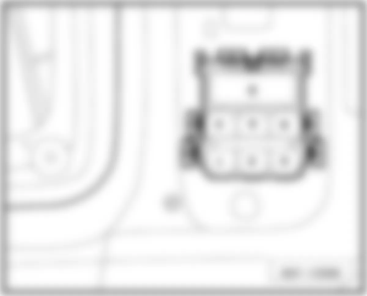
Audi A5 Quattro 2009 - 1.10- 3-PIN RELAY/FUSE PANEL (DIESEL)
NOTE: The 3-pin relay/fuse panel is located below the instrument panel, driver's side, on relay/fuse panel with vehicle electrical system control module (BCM1) and threaded connection, refer to illustrations below. For fuse identification and amperage rating refer to FUSE - COLOR CODES.
Fig. 29: Audi A5 Quattro 2009 - Component Locations - 3-Pin Relay /Fuse Panel

1.10 - FUSES:
Audi A5 Quattro 2009 IDENTIFYING FUSES (3-PIN RELAY/FUSE PANEL - DRIVER'S SIDE)
Position/Location Rating (Amps) Function/Component A - Not used B - Not used C 40A Auxiliary Heater Fuse -S126- (1) D 60A Auxiliary Heater Fuse 2 -S328- (1)
(1) Only models with diesel engine.
Audi A5 Quattro 2009 - 1.11- 6-PIN CONNECTOR STATION A-PILLAR - DRIVER'S SIDE
NOTE: The 6-pin connector station A-pillar is located in driver's footwell on A-pillar, behind side trim, refer to illustrations below. For fuse identification and amperage rating refer to FUSE - COLOR CODES.
1.11 - CIRCUIT BREAKERS:
Audi A5 Quattro 2009 IDENTIFYING FUSES (6-PIN CONNECTOR STATION A-PILLAR - DRIVER'S SIDE)
Position/Location Rating (Amps) Function/Component A - Not used B - Not used C - Not used D - Not used E - Not used F 30A Driver's and front passenger's seat circuit breaker -S346- (1) F 15A Front Passenger's Power Seat Adjustment Circuit Breaker 1 -S46- (2) G 15A Driver's Power Seat Adjustment Circuit Breaker 1 -S44- (2)
(1) Through June 2007.
(2) From June 2007.
Audi A5 Quattro 2009 - 1.12- 6-PIN CONNECTOR STATION A-PILLAR - PASSENGER SIDE
NOTE: The 6-pin connector station A-pillar is located in driver's footwell on A-pillar, behind side trim, refer to illustrations below. For fuse identification and amperage rating refer to FUSE - COLOR CODES.

1.12 - FUSES:
Audi A5 Quattro 2009 IDENTIFYING FUSES (6-PIN CONNECTOR STATION A-PILLAR - PASSENGER SIDE)
Position/Location Rating (Amps) Function/Component A - Not used B - Not used C - Not used D - Not used E - Not used F 40A ABS Control Module Fuse 1 -S123- (1) G1 25A ABS Control Module Fuse 3 -S137- (1) G2 10A ABS Control Module Fuse 2 -S124- (1)
(1) Only models with right-hand drive.
Audi A5 Quattro 2009 - 1.13- RELAY/FUSE PANEL WITH VEHICLE ELECTRICAL SYSTEM CONTROL MODULE -J519-
NOTE: This relay/fuse panel is located below the instrument panel, driver's side, refer to illustrations below. For fuse identification and amperage rating refer to FUSE - COLOR CODES.

1.12 - FUSES:
Audi A5 Quattro 2009 IDENTIFYING FUSE (RELAY/FUSE PANEL WITH VEHICLE ELECTRICAL SYSTEM CONTROL MODULE - DRIVER'S SIDE)
Position/Location Rating (Amps) Function/Component A 40A ABS Control Module Fuse 1 -S123- (1)
For models with right-hand drive, see 1.12 - 6-Pin Connector Station A-Pillar - Passenger Side. (1) Only models with left-hand drive.
Audi A5 Quattro 2009 - RELAY INDEX INFORMATION RELAY AND FUSE HOLDER BELOW INSTRUMENT PANEL - DRIVER'S SIDE 1.2- Relay / Fuse Panel with Vehicle Electrical System Control Module -J519-
NOTE: This relay and fuse holder is located below instrument panel on driver's side, refer to illustration below. For fuse identification, refer to 1.13 - Relay/Fuse Panel With Vehicle Electrical System Control Module -J519-.

Audi A5 Quattro 2009 IDENTIFYING RELAYS (RELAY/FUSE PANEL WITH VEHICLE ELECTRICAL SYSTEM CONTROL MODULE - DRIVER'S SIDE)
Position/Location Function/Component 1 Not used 2 Horn Relay -J413- 2 Automatic Day/Night Interior Mirror Relay -J910- 3 Power Supply Relay (terminal 15) -J329- (1) 4 Driving School Option
From August 2008 refer to 1.5 - Relay / Fuse Panel F -SF- in luggage compartment. (1) Component location applicable from September 2007, through August 2008.
Audi A5 Quattro 2009 - 1.3- 3 Pin Relay / Fuse Panel (Diesel)
NOTE: This relay and fuse holder is located below instrument panel drivers side on relay / fuse panel with Vehicle Electrical System Control Module -J519- and threaded connection. - illustration below. For fuse identification, refer to 1.10 - 3-Pin Relay/Fuse PanelFUSE INDEX INFORMATION.
Fig. 34: Audi A5 Quattro 2009 - Component Locations - 3-Pin Relay /Fuse Panel

Audi A5 Quattro 2009 IDENTIFYING RELAYS (3 PIN RELAY/FUSE PANEL (DIESEL) - DRIVER'S SIDE)
Position/Location Function/Component 1 Not used 2 Preheating Coolant, Low Heat Output Relay J359- (1) 2 Preheating Coolant, High Heat Output Relay -J360- (1)
(1) Only models with diesel engine.
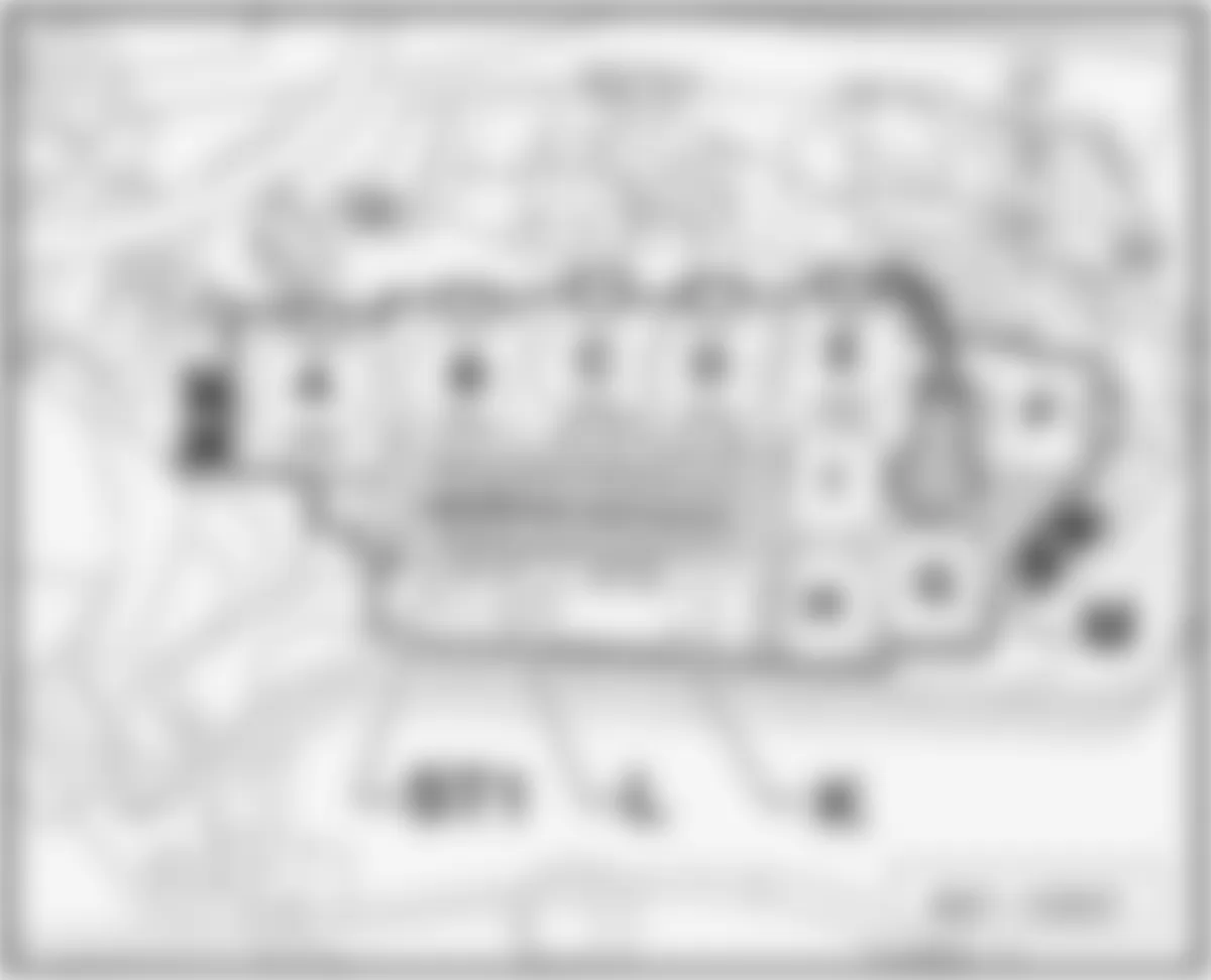
Audi A5 Quattro 2009 - RELAY AND FUSE HOLDER IN E-BOX PLENUM CHAMBER 1.4- Relay / Fuse Panel B -SB-
NOTE: This relay and fuse holder (s) in e-box plenum chamber is located on the left side of engine compartment, refer to illustration below. For fuse identification, refer to 1.3 - RELAY / FUSE PANEL B -SB- IN E-BOX PLENUM CHAMBER.
Fig. 35: Audi A5 Quattro 2009 - Component Locations - Relay / Fuse Panel B -SB-
Audi A5 Quattro 2009 IDENTIFYING RELAYS (ENGINE COMPARTMENT - IN E-BOX PLENUM CHAMBER)
Position/Location Function/Component A Automatic Glow Time Control Module -J179- (1) A Engine Component Power Supply Relay -J757- (2) (3) B Starter Relay -J53- B Starter Relay 2 -J695- C Secondary Air Injection (AIR) Pump Relay -J299- (3) D Power Supply Relay (terminal 30) -J317- (1) D Motronic Engine Control Module (ECM) Power Supply Relay -J271- (2) (3) E Fuel Pump (FP) Relay -J17- (1) E Auxiliary Fuel Pump Relay -J832- (1) E Coolant Circulation Pump Relay -J151- (2) E Auxiliary Engine Coolant (EC) Pump Relay -J496- (3) E Brake Booster Relay -J569- (4) F Not used
(1) Only models with diesel engine.
(2) Only models with 4 cylinder gasoline engine.
(3) Only models with 6 cylinder gasoline engine.
(4) Only models with 8 cylinder gasoline engine.
Audi A5 Quattro 2009 - RELAY AND FUSE HOLDER IN LUGGAGE COMPARTMENT - RIGHT SIDE 1.5- Relay / Fuse Panel F -SF-
NOTE: This luggage compartment relay / fuse holder is located on the right side interior of trunk, refer to illustrations below. For identification of all other fuses, circuit breakers and threaded connections, refer to 1.7 - FUSE PANEL F -SF- LUGGAGE COMPARTMENT - RIGHT SIDE (2008-09) and/or 1.8 - FUSE PANEL F -SF- LUGGAGE COMPARTMENT - RIGHT SIDE (2010).
Fig. 36: Audi A5 Quattro 2009 - Component Locations - Relay / Fuse Panel F -SF-

Audi A5 Quattro 2009 IDENTIFYING RELAYS (LUGGAGE COMPARTMENT - RIGHT SIDE)
Position/Location Function/Component A Not used B Not used C Rear Window Defogger Relay -J9- D Power Supply Relay (terminal 15) -J329- (1) E Sockets Relay -J807-
(1) Component location applicable from August 2008.