Audi Q7 4.2 2007 - 2007-09 ELECTRICAL Fuses & Circuit Breakers - Q7
Audi Q7 4.2 2007 - IDENTIFICATION
| WARNING: | Vehicles are equipped with air bag supplemental restraint system. Before attempting any repairs involving steering column, instrument panel or related components, see AIRBAG SAFETY PRECAUTIONS in RESTRAINTS article. |
Audi Q7 4.2 2007 - ENGINE CODE
Engines are identified by a 3 or 4 letter code stamped onto the engine block, for engine identification see engine code on the vehicle data plate.
| Engine Displacement | Engine Stamp Code |
| 3.0L - V6 |
| 2009 | CATA |
| 3.6L - V6 |
| 2007-09 | BHK |
| 4.2L - V8 |
| 2007-09 | BAR |
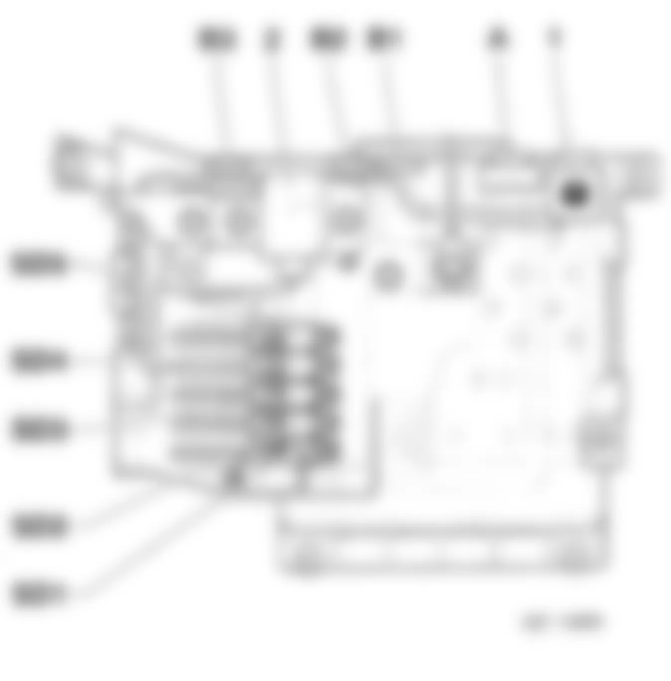
Audi Q7 4.2 2007 - COMPONENT LOCATION 1- FUSES 1.1- Fuses Overview

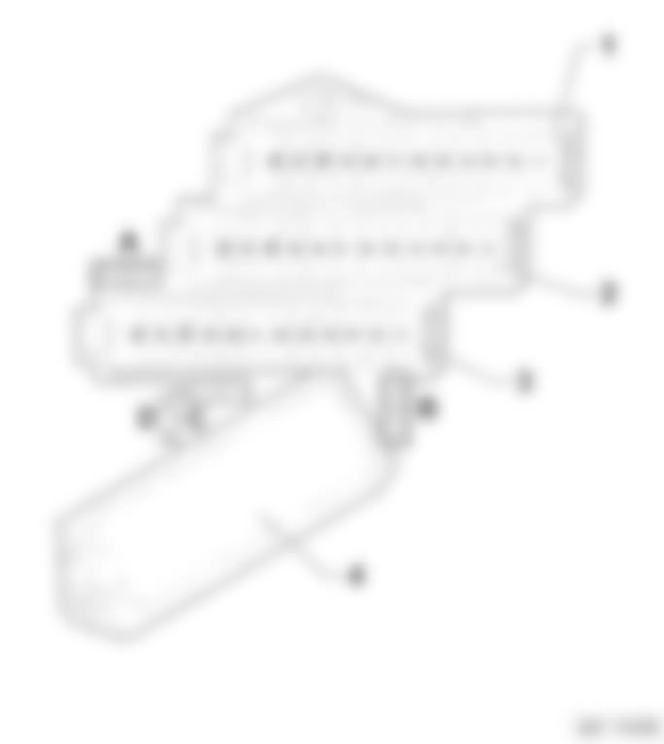
Fig. 1: Audi Q7 4.2 2007 - Component Locations - Identifying Location Of Relay & Fuse Panels
| Position No. | Description/Component | Location | Refer to |
| 1 | Fuse Panel -SC-
(Through May 2009) | On instrument panel, right side
(Behind end cover) | 1.3
Fig. 4 |
| 1 | Fuse Panel -SC-
(From June 2009) | On instrument panel, right side
(Behind end cover) | 1.4
Fig. 4 |
| 2 | Relay/Fuse Panel | Instrument panel, center | 1.10.2
Fig. 5 |
| 3 | Relay/Fuse -SF-
(Through May 2009) | In luggage compartment, right side | 1.11.3
Fig. 6 |
| 3 | Relay/Fuse -SF-
(From June 2009) | In luggage compartment, right side | 1.11.6
Fig. 6 |
| 4 | Relay/Fuse Panel -SD- | Below Driver Seat | 1.12
Fig. 7 |
| 5 | Fuse Panel -SB-
(Through May 2009) | On instrument panel, left side
(Behind end cover) | 1.2
Fig. 2 |
| 5 | Fuse Panel -SB-
(From June 2009) | On instrument panel, left side
(Behind end cover) | 1.2.7
Fig. 2 |
| 6 | Relay/Fuse Panel E-Box | In left plenum chamber
Gasoline engine | 1.13.2
Fig. 9 |
| 6 | Relay/Fuse Panel E-Box | In left plenum chamber
Diesel engine | 1.13.4
Fig. 9 |
Audi Q7 4.2 2007 - 1- RELAYS
At time of this writing relay information was not available. For relay information refer to the appropriate wiring diagrams.
Audi Q7 4.2 2007 - FUSE INDEX INFORMATION
| NOTE: | Whenever replacing a fuse, always consult the sticker on the inside of the fuse panel cover. It contains the most up-to-date information regarding the fuse arrangement. |
| NOTE: | The following fuse index tables are for left hand drive vehicles only. |
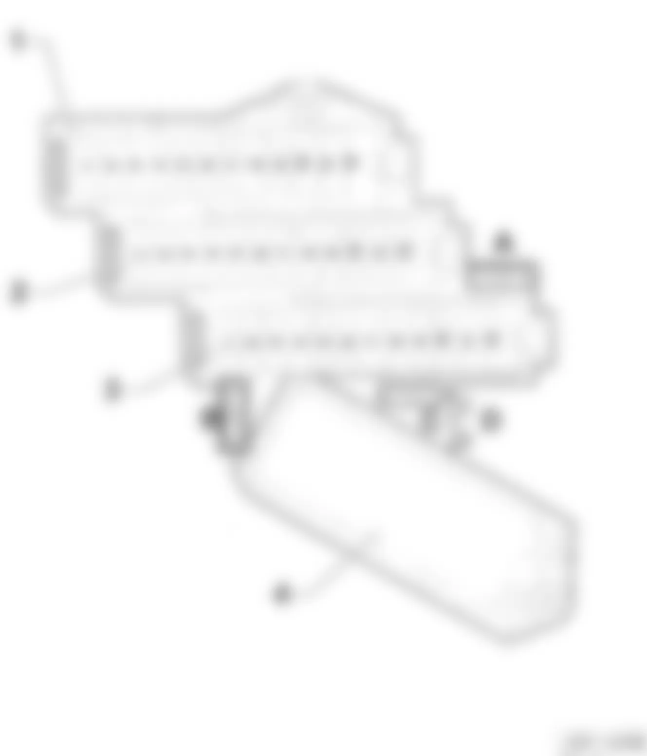
Audi Q7 4.2 2007 - 1.2- FUSE PANEL -SB- ON INSTRUMENT PANEL - LEFT SIDE
The left side instrument panel fuse holder is located on the left side end of the dash panel, refer to illustrations below. For fuse color code and amperage rating, refer to FUSE - COLOR CODES.
Fig. 2: Audi Q7 4.2 2007 - Component Locations - Identifying Instrument Panel Left Side Fuse Box
Fig. 3: Audi Q7 4.2 2007 - Component Locations - Identifying Instrument Panel (SB) Fuse Box - Left Side
Audi Q7 4.2 2007 - 1.2.1- Fuse Holder ST1 (Red), Instrument Panel - Left Side
Audi Q7 4.2 2007 IDENTIFYING FUSES IN HOLDER ST1 RED (INSTRUMENT PANEL - LEFT SIDE)
Fuse
No. | Rating
(Amps) | Function/Component | Wiring
ID. | Terminal |
| 1 | - | Not used | SB1 | - |
| 2 | - | Not used | SB2 | - |
| 3 | - | Not used | SB3 | - |
| 4 | 5A | -Tire Pressure Monitoring Control Module -J502 | SB4 | 30 |
| 5 | 20A | -Auxiliary Heater Control Module -J364 | SB5 | 30 |
| 6 | 10A | -Driver Seat Lumbar Support Adjustment Switch -E176 | SB6 | 30 |
| 7 | 35A | -Driver Door Control Module -J386
-Driver Window Regulator Motor -V147
-Left Rear Door Control Module -J388
-Left Rear Window Regulator Motor -V26 | - | 30 |
| 8 | 15A | -Driver Door Control Module -J386
-Left Rear Door Control Module -J388 (1) | SB8 | 30 |
| 9 | 5A | -Energy Management Control Module -J644 (1) | SB9 | 30 |
| 10 | 30A | -Access/Start Control Module -J518
-Access/Start Authorization Switch -E415 | SB10 | 30 |
| 11 | 10A | -Steering Column Electronic Systems Control Module -J527 | SB11 | 30 |
| 12 | 5A | -Interior Monitoring Sensor -G273
-Alarm Horn -H12 | SB12 | 30 |
| |
| NOTE: | Whenever replacing a fuse, always consult the sticker on the inside of the fuse panel cover. It contains the most up-to-date information regarding the fuse arrangement. |
Audi Q7 4.2 2007 - 1.2.2- Fuse Holder ST2 (Brown), Instrument Panel - Left Side
Audi Q7 4.2 2007 IDENTIFYING FUSES IN HOLDER ST2 BROWN (INSTRUMENT PANEL - LEFT SIDE)
Fuse
No. | Rating
(Amps) | Function/Component | Wiring
ID. | Terminal |
| 1 | - | Not used | SB1 | - |
| 2 | - | Not used | SB2 | - |
| 3 | - | Not used | SB3 | - |
| 4 | 30A | -Wiper Motor Control Module -J400
-Windshield Wiper Motor -V | SB4 | 30 |
| 5 | 5A | -Rain/Light Recognition Sensor -G397 | SB5 | 30 |
| 6 | 25A | -Horn Relay -J4
-High Tone Horn -H2
-Low Tone Horn -H7 | SB6 | 30 |
| 7 | 30A | -Vehicle Electrical System Control Module -J519 | - | 30 |
| 8 | 25A | -Vehicle Electrical System Control Module -J519 | SB8 | 30 |
| 9 | 25A | -Vehicle Electrical System Control Module -J519 | SB9 | 30 |
| 10 | 10A | -Instrument Cluster Control Module -J285
-Data Bus On Board Diagnostic Interface -J533
-Display Unit in Instrument Cluster -Y24 | SB10 | 30 |
| 11 | 30A | -Headlamp Washer Relay -J39 | SB11 | 30 |
| 12 | 10A | -16 Pin Connector -T16-, Data Link Connector (DLC) | SB12 | 30 |
Audi Q7 4.2 2007 - 1.2.3- Fuse Holder ST3 (Black), Instrument Panel - Left Side
Audi Q7 4.2 2007 IDENTIFYING FUSES IN HOLDER ST3 BLACK (INSTRUMENT PANEL - LEFT SIDE)
Fuse
No. | Rating
(Amps) | Function/Component | Wiring
ID. | Terminal |
| 1 | 10A | -Left Headlamp | SB1 | 15 |
| 2 | 5A | -Distance Regulation Control Module -J428
-Distance Regulation Sensor Heater -Z47 | SB2 | 15 |
| 3 | 5A | -Side View (1)
-Display Unit -J145
-Display Unit Button -E506 | SB3 | 15 |
| 4 | 10A | -Lane-Departure-Warning
-Directional Stabilization Assistance Control Module -J759
-Directional Stabilization Assistance Windshield Heater -Z67 | SB4 | 15 |
| 5 | 10A
5A (2) | -Signal System Control Module -J616
-Special Signals Control Head -E507
-Preparation for Multimedia (9WM) (2) | SB5 | 15 |
| 6 | 5A | -Steering Column Electronic Systems Control Module -J527
-Access/Start Control Module -J518
-Light Switch -E1
-Comfort System Central Control Module -J393
-Towing Recognition Control Module -J345
-Tire Pressure Monitoring Control Module -J502 (7K6) (3) | SB6 | 15 |
| 7 | 5A | -Oil Level Thermal Sensor -G266 | - | 15 |
| 8 | 5A | -16 Pin Connector T16 Data Link Connector (DLC) | SB8 | 15 |
| 9 | 5A | -Automatic Day/Night Interior Mirror -Y7 | SB9 | 15 |
| 10 | 5A | -Garage Door Opener Control Module -J530
-Garage Door Opener Control Head -E284 | SB10 | 15 |
| 11 | 5A | -Data Bus On Board Diagnostic Interface -J533 | SB11 | 15 |
| 12 | 5A | -Headlamp Adjuster -E102
-Left Headlamp Beam Adjustment Motor -V48
-Right Headlamp Beam Adjustment Motor V49 | SB12 | 15 |
| (1) | Only for vehicles with Japanese equipment. | |
Audi Q7 4.2 2007 - 1.2.7- Fuse Holder ST1 (Red), Instrument Panel - Left Side (From June 2009)
Audi Q7 4.2 2007 IDENTIFYING FUSES IN HOLDER ST1 RED (INSTRUMENT PANEL - LEFT SIDE - FROM JUNE 2009)
Fuse
No. | Rating
(Amps) | Function/Component | Wiring
ID. | Terminal |
| 1 | - | Not used | SB1 | - |
| 2 | - | Not used | SB2 | - |
| 3 | - | Not used | SB3 | - |
| 4 | 5A | -Tire Pressure Monitoring Control Module -J502 | SB4 | 30 |
| 5 | 20A | -Auxiliary Heater Control Module -J364 | SB5 | 30 |
| 6 | 10A | -Driver Seat Lumbar Support Adjustment Switch -E176 | SB6 | 30 |
| 7 | 35A | -Driver Door Control Module -J386
-Driver Window Regulator Motor -V147
-Left Rear Door Control Module -J388
-Left Rear Window Regulator Motor -V26 | - | 30 |
| 8 | 15A | -Driver Door Control Module -J386 | SB8 | 30 |
| 9 | - | Not used | SB9 | - |
| 10 | 30A | -Access/Start Control Module -J518
-Access/Start Authorization Switch -E415 | SB10 | 30 |
| 11 | 10A | -Steering Column Electronic Systems Control Module -J527 | SB11 | 30 |
| 12 | 5A | -Interior Monitoring Sensor -G273
-Alarm Horn -H12 | SB12 | 30 |
Audi Q7 4.2 2007 - 1.2.8- Fuse Holder ST2 (Brown), Instrument Panel - Left Side (From June 2009)
Audi Q7 4.2 2007 IDENTIFYING FUSES IN HOLDER ST2 BROWN (INSTRUMENT PANEL - LEFT SIDE - FROM JUNE 2009)
Fuse
No. | Rating
(Amps) | Function/Component | Wiring
ID. | Terminal |
| 1 | - | Not used | SB1 | - |
| 2 | - | Not used | SB2 | - |
| 3 | 15A | Left Front Comfort Seat (Q2J) | SB3 | 30 |
| 4 | 30A | -Wiper Motor Control Module -J400
-Windshield Wiper Motor -V | SB4 | 30 |
| 5 | 5A | -Rain/Light Recognition Sensor -G397 | SB5 | 30 |
| 6 | 25A | -Horn Relay -J4
-High Tone Horn -H2
-Low Tone Horn -H7 | SB6 | 30 |
| 7 | 30A | -Vehicle Electrical System Control Module -J519 | - | 30 |
| 8 | 25A | -Vehicle Electrical System Control Module -J519 | SB8 | 30 |
| 9 | 25A | -Vehicle Electrical System Control Module -J519 | SB9 | 30 |
| 10 | 10A | -Instrument Cluster Control Module -J285
-Data Bus On Board Diagnostic Interface -J533
-Display Unit in Instrument Cluster -Y24 | SB10 | 30 |
| 11 | 30A | -Headlamp Washer Relay -J39 | SB11 | 30 |
| 12 | 10A | -16 Pin Connector -T16-, Data Link Connector (DLC) | SB12 | 30 |
Audi Q7 4.2 2007 - 1.2.9- Fuse Holder ST3 (Black), Instrument Panel - Left Side (From June 2009)
Audi Q7 4.2 2007 IDENTIFYING FUSES IN HOLDER ST3 BLACK (INSTRUMENT PANEL - LEFT SIDE - FROM JUNE 2009)
Fuse
No. | Rating
(Amps) | Function/Component | Wiring
ID. | Terminal |
| 1 | 10A | -Left Headlamp | SB1 | 15 |
| 2 | 5A | -Distance Regulation Control Module -J428
-Distance Regulation Sensor Heater -Z47 | SB2 | 15 |
| 3 | 5A | -Side View (1)
-Display Unit -J145
-Display Unit Button -E506 | SB3 | 15 |
| 4 | 10A | -Lane-Departure-Warning
-Directional Stabilization Assistance Control Module -J759
-Directional Stabilization Assistance Windshield Heater -Z67 | SB4 | 15 |
| 5 | 5A | -Preparation for Multimedia (9WM) | SB5 | 15 |
| 6 | 5A | -Steering Column Electronic Systems Control Module -J527
-Access/Start Control Module -J518
-Light Switch -E1
-Comfort System Central Control Module -J393
-Towing Recognition Control Module -J345
-Tire Pressure Monitoring Control Module -J502 (7K6) | SB6 | 15 |
| 7 | 5A | -Oil Level Thermal Sensor -G266 | - | 15 |
| 8 | 5A | -16 Pin Connector T16 Data Link Connector (DLC) | SB8 | 15 |
| 9 | 5A | -Automatic Day/Night Interior Mirror -Y7 | SB9 | 15 |
| 10 | 5A | -Garage Door Opener Control Module -J530
-Garage Door Opener Control Head -E284 | SB10 | 15 |
| 11 | 5A | -Data Bus On Board Diagnostic Interface -J533 | SB11 | 15 |
| 12 | 5A | -Headlamp Adjuster -El02
-Left Headlamp Beam Adjustment Motor -V48
-Right Headlamp Beam Adjustment Motor V49 | SB12 | 15 |
| (1) | Only for vehicles with Japanese equipment. | |
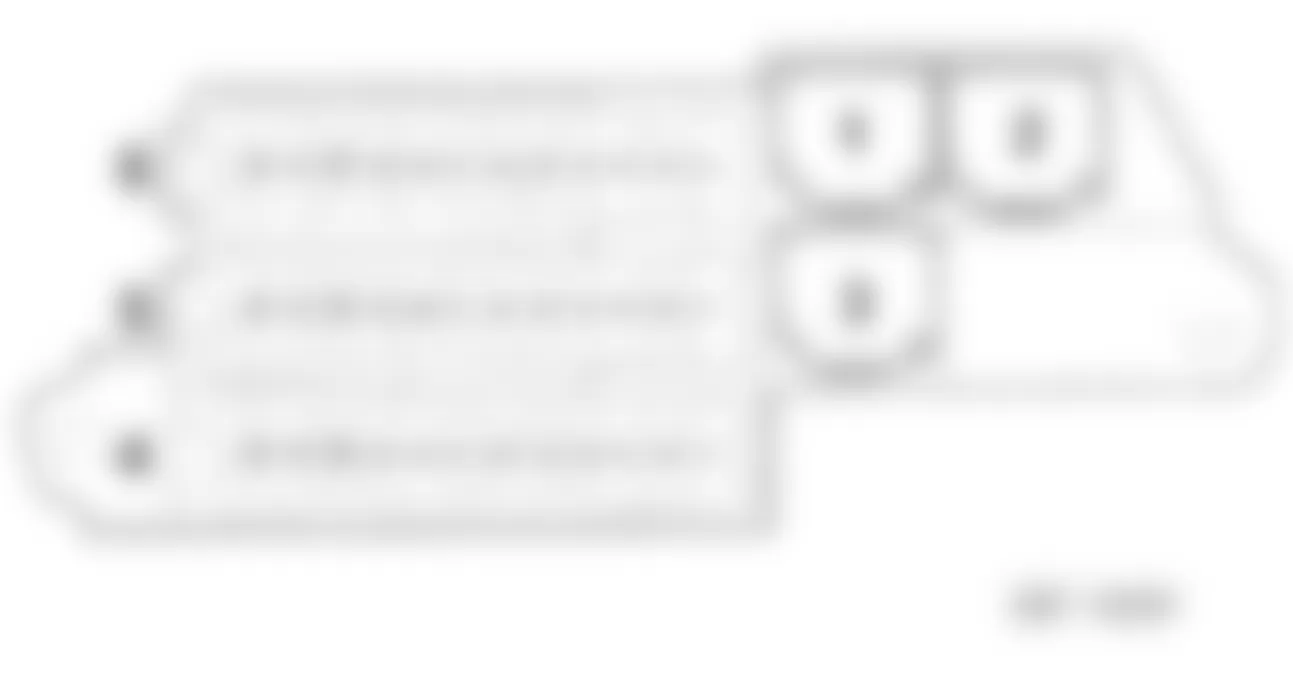
Audi Q7 4.2 2007 - 1.3- FUSE PANEL -SC- ON INSTRUMENT PANEL - RIGHT SIDE
The right side instrument panel fuse holder is located on the right side end of the dash panel, refer to illustration below. For fuse color code and amperage rating, refer to FUSE - COLOR CODES.
Fig. 4: Audi Q7 4.2 2007 - Component Locations - Identifying Instrument Panel (SC) Fuse Box - Right Side
| Location No. | Description/Component | Fuse Index |
| 1 | ST1 - Fuse Holder 1 (Black) | 1.3.2- ST1 (Black) |
| 1 | ST1 - Fuse Holder 1 (Black)
(From June 2009) | 1.4- ST1 (Black) |
| 2 | ST2 - Fuse Holder 2 (Brown) | 1.3.3- ST2 (Brown) |
| 2 | ST2 - Fuse Holder 2 (Brown)
(From June 2009) | 1.5- ST2 (Brown) |
| 3 | ST3 - Fuse Holder 3 (Red) | 1.3.4- ST3 (Red) |
| 3 | ST3 - Fuse Holder 3 (Red)
(From June 2009) | 1.6- ST3 (Red) |
| 4 | CAN Disconnection Plug | NA |
| A | Structure-Borne Sound Control Module Fuse -S348-, 5A | - |
| B | Cooler Fuse -S340-, 5A
From June 2008 | - |
| C | Not used | - |
| D | Not used | - |
Audi Q7 4.2 2007 - 1.3.2- Fuse Holder ST1 (Black), Instrument Panel - Right Side
Audi Q7 4.2 2007 IDENTIFYING FUSES IN HOLDER ST1 BLACK (INSTRUMENT PANEL - RIGHT SIDE)
Fuse
No. | Rating
(Amps) | Function/Component | Wiring
ID. | Terminal |
| 1 | 20A | -Left Rear Seat Heating Element -Z10
-Left Rear Backrest Heating Element -Z11
-Right Rear Seat Heating Element -Z12
-Right Rear Backrest Heating Element -Z13 | SC1 | 30 |
| 2 | 10A | -Transmission Control Module (TCM) -J217- (0AT) | SC2 | 30 |
| 2 | 5A | -Transmission Control Module (TCM) -J217- (09D) | SC2 | 30 |
| 3 | 30A | -Left Front Heated Seat -Z45
-Right Front Heated Seat -Z46 | SC3 | 30 |
| 4 | 20A | -ABS Control Module -J104 | SC4 | 30 |
| 5 | 15A | -Front Passenger Door Control Module -J387
-Right Rear Door Control Module -J389 (1) | SC5 | 30 |
| 6 | 25A | -12V Socket 3 -U19
-12V Socket 4 -U20 | SC6 | 30 |
| 7 | 10A | -Front Passenger Seat Lumbar Support Adjustment Switch -E177 | SC7 | 30 |
| 8 | 20A | -Cigarette Lighter -U1 | SC8 | 30 |
| 9 | 25A | -12V Socket -U5
-12V Socket 2 -U18 | SC9 | 30 |
| 10 | 10A | -Climatroriic Control Module -J255
-Fresh Air Blower Control Module -J126 | SC10 | 30 |
| 11 | 5A | -Brake Light Switch -F (1)
-Brake Pedal Switch -F47 (1)
-ABS Control Module -J104 (1) | SC11 | 30 |
| 12 | 15A | -Vehicle Electrical System Control Module 2 -J520 | SC12 | 30 |
| |
Audi Q7 4.2 2007 - 1.3.3- Fuse Holder ST2 (Brown), Instrument Panel - Right Side
Audi Q7 4.2 2007 IDENTIFYING FUSES IN HOLDER ST2 BROWN (INSTRUMENT PANEL - RIGHT SIDE)
Fuse
No. | Rating
(Amps) | Function/Component | Wiring
ID. | Terminal |
| 1 | 10A | -Right Headlamp | SC1 | 15 |
| 2 | 5A | -Level Control System Control Module -J197 | SC2 | 15 |
| 3 | 5A | -Preparation for Cellular Telephone Preparation (9ZD) | SC3 | 15 |
| 4 | 5A | -Lane Change Assistance Control Module -J769
-Lane Change Assistance Control Module 2 -J770 | SC4 | 15 |
| 5 | 5A | -Brake Light Disable Relay (ESP) -J508
-Clutch Pedal Switch -F36 | SC5 | 15 |
| 6 | 5A | -Transmission Control Module (TCM) -J217- (0AT) | SC6 | 15 |
| 6 | 20A | -Transmission Control Module (TCM) -J217- (09D) | SC6 | 15 |
| 7 | 5A | -ABS Control Module -J104 | SC7 | 15 |
| 8 | 5A | -Multi-Function Transmission Range (TR) Switch -F125
-Tiptronic Switch -F189
-Selector Lever Sensor System Control Module -J587 | SC8 | 15 |
| 9 | 5A | -Parking Aid Control Module -J446 | SC9 | 15 |
| 10 | 5A | -Airbag Control Module -J234 | SC10 | 15 |
| 11 | 5A | -Left Rear Heated Seat Regulating Switch -E128
-Right Rear Heated Seat Regulating Switch -E129 | SC11 | 15 |
| 12 | 5A | -Air Quality Sensor -G238
-Rear A/C Display Control Head (Climatronic) -E265
-Climatronic Control Module -J255 | SC12 | 15 |
Audi Q7 4.2 2007 - 1.3.4- Fuse Holder ST3 (Red), Instrument Panel - Right Side
Audi Q7 4.2 2007 IDENTIFYING FUSES IN HOLDER ST3 RED (INSTRUMENT PANEL - RIGHT SIDE)
Fuse
No. | Rating
(Amps) | Function/Component | Wiring
ID. | Terminal |
| 1 | 10A | -Rear Window Wiper Motor -V12 (1)
-Cooler -J698 (2) | SC1 | 75 |
| 2 | 5A | -Left Washer Nozzle Heater -Z20
-Right Washer Nozzle Heater -Z21 | SC2 | 75 |
| 3 | - | Not used | SC3 | - |
| 4 | - | Not used | SC4 | - |
| 5 | 5A | -Telephone Transceiver -R36 | SC5 | 30 |
| 6 | 15A | -Front Information Display Control Head Control Module -J523
-Antenna Amplifier -R24 | SC6 | 30 |
| 6 | 7.5A | -Front Information Display Control Head Control Module -J523 | SC6 | 30 |
| 7 | 20A | -Power Sunroof Control Module -J245 | SC7 | 30 |
| 8 | 20A | -Rear Sliding Sunroof Control Module -J392 | SC8 | 30 |
| 9 | 20A | -Roof Blind Control Module -J394 | SC9 | 30 |
| 10 | 5A | -Media Player, Position 1 -R118
-Media Player, Position 2 -R119
-CD Changer -R41
-Mini Disk Player -R153
-Video Recorder/DVD-player -R129
External Audio Source Connection -R199 (3) | SC10 | 30 |
| 11 | 35A | -Front Passenger Window Regulator Motor -V148
-Right Rear Window Regulator Motor -V27 | SC11 | 30 |
| 12 | 10A | -Rear A/C Display Control Head (Climatronic) -E265
-Rear Fresh Air Blower Control Module -J391 | SC12 | 30 |
| |
Audi Q7 4.2 2007 - 1.4- Fuse Holder ST1 (Black), Instrument Panel - Right Side (From June 2009)
Audi Q7 4.2 2007 IDENTIFYING FUSES IN HOLDER ST1 BLACK (INSTRUMENT PANEL - RIGHT SIDE - FROM JUNE 2009)
Fuse
No. | Rating
(Amps) | Function/Component | Wiring
ID. | Terminal |
| 1 | 20A | -Left Rear Seat Heating Element -Z10
-Left Rear Backrest Heating Element -Z11
-Right Rear Seat Heating Element -Z12
-Right Rear Backrest Heating Element -Z13 | SC1 | 30 |
| 2 | 10A | -Transmission Control Module (TCM) -J217- (0AT) | SC2 | 30 |
| 2 | 5A | -Transmission Control Module (TCM) -J217- (09D) | SC2 | 30 |
| 3 | 30A | -Left Front Heated Seat -Z45
-Right Front Heated Seat -Z46 | SC3 | 30 |
| 3 | 15A | -Right Front Comfort Seat (Q2J) | SC3 | 30 |
| 4 | 20A | -ABS Control Module -J104 | SC4 | 30 |
| 5 | 15A | -Front Passenger Door Control Module -J387 | SC5 | 30 |
| 6 | 25A | -12V Socket 3 -U19
-12V Socket 4 -U20 | SC6 | 30 |
| 7 | 10A | -Front Passenger Seat Lumbar Support Adjustment Switch -E177 | SC7 | 30 |
| 8 | 20A | -Cigarette Lighter -U1 | SC8 | 30 |
| 9 | 25A | -12V Socket -U5
-12V Socket 2 -U18 | SC9 | 30 |
| 10 | 10A | -Climatroriic Control Module -J255
-Fresh Air Blower Control Module -J126 | SC10 | 30 |
| 11 | - | Not used | SC11 | - |
| 12 | 15A | -Vehicle Electrical System Control Module 2 -J520 | SC12 | 30 |
Audi Q7 4.2 2007 - 1.5- Fuse Holder ST2 (Brown), Instrument Panel - Right Side (From June 2009)
Audi Q7 4.2 2007 IDENTIFYING FUSES IN HOLDER ST2 BROWN (INSTRUMENT PANEL - RIGHT SIDE - FROM JUNE 2009)
Fuse
No. | Rating
(Amps) | Function/Component | Wiring
ID. | Terminal |
| 1 | 10A | -Right Headlamp | SC1 | 15 |
| 2 | 5A | -Level Control System Control Module -J197 | SC2 | 15 |
| 3 | 5A | -Preparation for Cellular Telephone Preparation (9ZD) | SC3 | 15 |
| 4 | 5A | -Lane Change Assistance Control Module -J769
-Lane Change Assistance Control Module 2 -J770 | SC4 | 15 |
| 5 | 5A | -Brake Light Disable Relay (ESP) -J508 | SC5 | 15 |
| 6 | 5A | -Transmission Control Module (TCM) -J217- (0AT) | SC6 | 15 |
| 6 | 20A | -Transmission Control Module (TCM) -J217- (09D) | SC6 | 15 |
| 7 | 5A | -ABS Control Module -J104 | SC7 | 15 |
| 8 | 5A | -Multi-Function Transmission Range (TR) Switch -F125
-Tiptronic Switch -F189
-Selector Lever Sensor System Control Module -J587 | SC8 | 15 |
| 9 | 5A | -Parking Aid Control Module -J446 | SC9 | 15 |
| 10 | 5A | -Airbag Control Module -J234 | SC10 | 15 |
| 11 | 5A | -Left Rear Heated Seat Regulating Switch -E128
-Right Rear Heated Seat Regulating Switch -E129 | SC11 | 15 |
| 12 | 5A | -Air Quality Sensor -G238
-Rear A/C Display Control Head (Climatronic) -E265
-Climatronic Control Module -J255 | SC12 | 15 |
Audi Q7 4.2 2007 - 1.6- Fuse Holder ST3 (Red), Instrument Panel - Right Side (From June 2009)
Audi Q7 4.2 2007 IDENTIFYING FUSES IN HOLDER ST3 RED (INSTRUMENT PANEL - RIGHT SIDE - FROM JUNE 2009)
Fuse
No. | Rating
(Amps) | Function/Component | Wiring
ID. | Terminal |
| 1 | 10A | -Cooler -J698 | SC1 | 30 |
| 2 | - | Not used | SC2 | - |
| 3 | - | Not used | SC3 | - |
| 4 | 5A | -Front Information Display Control Head -J685 | SC4 | 30 |
| 5 | 5A | -Telephone Baseplate -R126
-Chip Card Reader Control Module -J676 | SC5 | 30 |
| 6 | 7.5A | -Information Electronics Control Module 1 -J794 | SC6 | 30 |
| 7 | 20A | -Power Sunroof Control Module -J245 | SC7 | 30 |
| 8 | 20A | -Rear Sliding Sunroof Control Module -J392 | SC8 | 30 |
| 9 | 20A | -Roof Blind Control Module -J394 | SC9 | 30 |
| 10 | 5A | -DVD Player -R7
-CD Changer -R41 | SC10 | 30 |
| 11 | 35A | -Front Passenger Window Regulator Motor -V148
-Right Rear Window Regulator Motor -V27 | SC11 | 30 |
| 12 | 10A | -Rear A/C Display Control Head (Climatronic) -E265
-Rear Fresh Air Blower Control Module -J391 | SC12 | 30 |
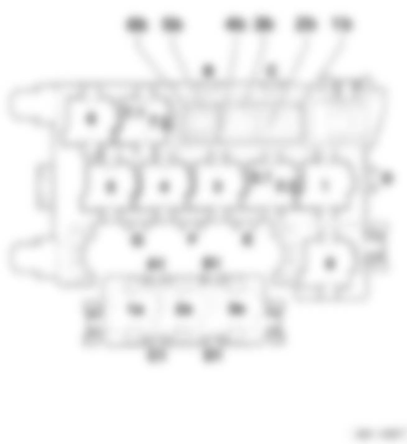
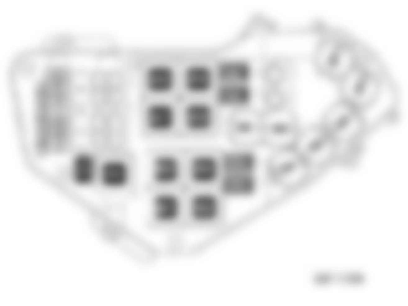
Audi Q7 4.2 2007 - 1.10- RELAY & FUSE PANEL INSTRUMENT PANEL - CENTER
The relay/fuse panel is located in instrument panel, center, refer to illustration below. For fuse color code and amperage rating, refer to FUSE - COLOR CODES.
Fig. 5: Audi Q7 4.2 2007 - Component Locations - Identifying Relay & Fuse Panel Instrument Panel - Center
Audi Q7 4.2 2007 - 1.10.2- Fuses In Relay/Fuse Holder Instrument Panel - Center
Audi Q7 4.2 2007 IDENTIFYING FUSES (RELAY & FUSE PANEL INSTRUMENT PANEL - CENTER)
| Location | Rating
(Amps) | Function/Component | Wiring
ID. | Terminal
No. |
| B | - | -Vacant | - | - |
| C | 30A | -Towing Recognition Control Module (only USA) -J345
-Brake Booster (only USA) | Trailer Circuit Breaker -S87 | 30 |
| D | 30A | -Memory Seat/Steering Column Adjustment Control Module -J136
-Passenger Memory Seat Control Module -J521 | Driver Power Seat Adjustment Circuit Breaker 1 -S44 | 30 |
| E | - | -Vacant | - | - |
| F | - | -Vacant | - | - |
| G | - | -Vacant | - | - |
| 1b | 40A | -Fresh air blower -V2 | Fresh Air Blower Fuse 1 -S97 | 30 |
| 2b | 40A | -ABS Control Module -J104 | ABS Control Module Fuse 1 -S123 | 30 |
| 3b | 40A | -Rear Fresh Air Blower -V80- | Fresh Air Blower Fuse 2 -S98 | 30 |
| 4b | 40A | -Heated Rear Window -Z1 | Rear Window Defogger Fuse -S41 | 30 |
| 5b | 15A | Rear Window Wiper Motor -V12 (1) | Rear Window Wiper Fuse -S30 | 75 |
| 6b | 5A | -Left Washer Nozzle Heater -Z20 (1)
-Right Washer Nozzle Heater -Z21(1) | Fuse S51 | 75 |
| A1 | - | Vacant | - | - |
| B1 | - | Vacant | - | - |
| C1 | - | Vacant | - | - |
| D1 | - | Vacant | - | - |
| |
Audi Q7 4.2 2007 - 1.11- RELAY/FUSE PANEL -SF- IN LUGGAGE COMPARTMENT - RIGHT SIDE
The relay/fuse panel -SF- is located in luggage compartment on the right side interior, refer to illustrations below. For fuse color code and amperage rating, refer to FUSE - COLOR CODES.
Fig. 6: Audi Q7 4.2 2007 - Component Locations - Identifying Relay & Fuse Panel In Luggage Compartment - Right Side
| Location No. | Description/Component | Fuse Index |
| 1 | Not used | - |
| 2 | Not used | - |
| 3 | Not used
(Through October 2007) | - |
| 3 | 6-Pin Connector -T6am- for Rear Seat Entertainment
(From November 2007) | - |
| 4 | Fuse Holder ST3 (Red) | 1.11.5- ST3 (Red) |
| 5 | Fuse Holder ST2 (Brown) | 1.11.4- ST2 (Brown) |
| 6 | Fuse Holder ST1 (Black) | 1.11.3- ST1 (Black) |
Audi Q7 4.2 2007 - 1.11.3- Fuse Holder ST1 (Black), Luggage Compartment
Audi Q7 4.2 2007 IDENTIFYING FUSES IN HOLDER ST1 BLACK (LUGGAGE COMPARTMENT)
Fuse
No. | Rating
(Amps) | Function/Component | Wiring
ID. | Terminal |
| 1 | 15A | -Signal System Control Module -J616 | SF1 | 30 |
| 2 | 30A | -Reducing Agent Metering System Control Module -J880 | SF2 | 30 |
| 3 | 15A | -Level Control System Control Module -J197 | SF3 | 30 |
| 4 | - | Not used | SF4 | - |
| 5 | 5A | -Parking Aid Control Module -J446 | SF5 | 30 |
| 6 | 15A | -Comfort System Central Control Module 2 -J773 | SF6 | 30 |
| 7 | 15A | -Comfort System Central Control Module 2 -J773 | SF7 | 30 |
| 8 | 5A | -Auxiliary Heater Radio Receiver -R64 | SF8 | 30 |
| 9 | 20A | -12V Socket 5 -U26 | SF9 | 30 |
| 10 | 20A | -Comfort System Central Control Module -J393 | SF10 | 30 |
| 11 | 15A | -Keyless Access Authorization Antenna Reader -J723 | SF11 | 30 |
| 12 | 30A | -Comfort System Central Control Module -J393 | SF12 | 30 |
Audi Q7 4.2 2007 - 1.11.4- Fuse Holder ST2 (Brown), Luggage Compartment
Audi Q7 4.2 2007 IDENTIFYING FUSES IN HOLDER ST2 BROWN (LUGGAGE COMPARTMENT)
Fuse
No. | Rating
(Amps) | Function/Component | Wiring
ID. | Terminal |
| 1 | 15A | -Signal System Control Module -J616 | SF1 | 30 |
| 2 | 5A | -Special Signals Control Head -E507 | SF2 | 30 |
| 3 | 15A | -Two-Way Radio Cut-Off Relay -J84
-Two-Way Radio -R8 | SF3 | 30 |
| 4 | 15A | -Two-Way Radio Cut-Off Relay -J84
-Two-Way Radio -R8 | SF4 | 30 |
| 5 | 5A | -Radio -R | SF5 | 30 |
| 6 | 5A | -TV Tuner -R78 | SF6 | 30 |
| 7 | 5A | -Navigation System with CD Drive Control Module -J401 | SF7 | 30 |
| 8 | 30A | -Digital Sound System Control Module -J525 | SF8 | 30 |
| 9 | 5A | -Digital Radio (DAB) -R147 | SF9 | 30 |
| 10 | 30A | -Digital Sound System Control Module 2 -J787 | SF10 | 30 |
| 11 | 5A | -Rear View Camera System Control Module -J772
-Rear View Camera -R189 | SF11 | 30 |
| 12 | - | Not used | SF12 | - |
Audi Q7 4.2 2007 - 1.11.5- Fuse Holder ST3 (Red), Luggage Compartment
Audi Q7 4.2 2007 IDENTIFYING FUSES IN HOLDER ST3 RED (LUGGAGE COMPARTMENT)
Fuse
No. | Rating
(Amps) | Function/Component | Wiring
ID. | Terminal |
| 1 | - | Not used | SF1 | - |
| 2 | - | Not used | SF2 | - |
| 3 | - | Not used | SF3 | - |
| 4 | - | Not used | SF4 | - |
| 5 | 15A | -Rear Seat Entertainment (9WP, 9WK) (2)
-Multimedia Control Module -J650 | SF5 | 30 |
| 6 | 20A | -Comfort System Central Control Module -J393 | SF6 | 30 |
| 7 | 30A | -Rear Lid Control Module -J605
-Motor (in rear lid control module) -V375 | SF7 | 30 |
| 8 | 30A | -Rear Lid Control Module 2 -J756
-Motor (in rear lid control module 2) -V376 | SF8 | 30 |
| 9 | 15A | -Towing Recognition Control Module -J345 | SF9 | 30 |
| 10 | 15A
20A (1) | -Towing Recognition Control Module -J345 | SF10 | 30 |
| 11 | 15A
20A (1) | -Towing Recognition Control Module -J345 | SF11 | 30 |
| 12 | 30A
25A(1) | -Towing Recognition Control Module -J345
-Swiveling Ball Head Motor -V317 | SF12 | 30 |
| |
Audi Q7 4.2 2007 - 1.11.6- Fuses In Fuse Holder ST1 (Black), Luggage Compartment (From June 2009)
Audi Q7 4.2 2007 IDENTIFYING FUSES IN HOLDER ST1 BLACK (LUGGAGE COMPARTMENT - FROM JUNE 2009))
Fuse
No. | Rating
(Amps) | Function/Component | Wiring
ID. | Terminal |
| 1 | 15A | -Signal System Control Module -J616 | SF1 | 30 |
| 2 | 30A | -Reducing Agent Metering System Control Module -J880 | SF2 | 30 |
| 3 | 15A | -Level Control System Control Module -J197 | SF3 | 30 |
| 4 | 5A | -Rear View Camera System Control Module -J772
Rear View Camera -R189 | SF4 | 30 |
| 5 | 5A | -Parking Aid Control Module -J446 | SF5 | 30 |
| 6 | 15A | -Comfort System Central Control Module 2 -J773 | SF6 | 30 |
| 7 | 15A | -Comfort System Central Control Module 2 -J773 | SF7 | 30 |
| 8 | 5A | -Auxiliary Heater Radio Receiver -R64 | SF8 | 30 |
| 9 | 20A | -12V Socket 5 -U26 | SF9 | 30 |
| 10 | 20A | -Comfort System Central Control Module -J393 | SF10 | 30 |
| 11 | 15A | -Keyless Access Authorization Antenna Reader -J723 | SF11 | 30 |
| 12 | 30A | -Comfort System Central Control Module -J393 | SF12 | 30 |
Audi Q7 4.2 2007 - 1.11.7- Fuses In Fuse Holder ST2 (Brown), Luggage Compartment (From June 2009)
Audi Q7 4.2 2007 IDENTIFYING FUSES IN HOLDER ST2 BROWN (LUGGAGE COMPARTMENT - FROM JUNE 2009)
Fuse
No. | Rating
(Amps) | Function/Component | Wiring
ID. | Terminal |
| 1 | 15A | -Signal System Control Module -J616 | SF1 | 30 |
| 2 | 5A | -Special Signals Control Head -E507 | SF2 | 30 |
| 3 | 15A | -Two-Way Radio Cut-Off Relay -J84
-Two-Way Radio -R8 | SF3 | 30 |
| 4 | 15A | -Two-Way Radio Cut-Off Relay -J84
-Two-Way Radio -R8 | SF4 | 30 |
| 5 | - | Not used | SF5 | - |
| 6 | - | Not used | SF6 | - |
| 7 | - | Not used | SF7 | - |
| 8 | - | Not used | SF8 | - |
| 9 | - | Not used | SF9 | - |
| 10 | - | Not used | SF10 | - |
| 11 | - | Not used | SF11 | - |
| 12 | - | Not used | SF12 | - |
Audi Q7 4.2 2007 - 1.11.8- Fuses In Fuse Holder ST3 (Red), Luggage Compartment (From June 2009)
Audi Q7 4.2 2007 IDENTIFYING FUSES IN HOLDER ST3 RED (LUGGAGE COMPARTMENT - FROM JUNE 2009)
Fuse
No. | Rating
(Amps) | Function/Component | Wiring
ID. | Terminal |
| 1 | 5A | -Radio -R | SF1 | 30 |
| 2 | 5A | -TV Tuner -R78 | SF2 | 30 |
| 3 | 30A | -Digital Sound System Control Module -J525 | SF3 | 30 |
| 4 | 30A | -Digital Sound System Control Module 2 -J787 | SF4 | 30 |
| 5 | 15A | -Rear Seat Entertainment (9WP, 9WK)
-Multimedia Control Module -J650 | SF5 | 30 |
| 6 | 20A | -Comfort System Central Control Module -J393 | SF6 | 30 |
| 7 | 30A | -Rear Lid Control Module -J605
-Motor (in rear lid control module) -V375 | SF7 | 30 |
| 8 | 30A | -Rear Lid Control Module 2 -J756
-Motor (in rear lid control module 2) -V376 | SF8 | 30 |
| 9 | 15A | -Towing Recognition Control Module -J345 | SF9 | 30 |
| 10 | 20A | -Towing Recognition Control Module -J345 | SF10 | 30 |
| 11 | 20A | -Towing Recognition Control Module -J345 | SF11 | 30 |
| 12 | 25A | -Towing Recognition Control Module -J345
-Swiveling Ball Head Motor -V317 | SF12 | 30 |
Audi Q7 4.2 2007 - 1.12- RELAY/FUSE PANEL -SD- BELOW DRIVER SEAT
The relay/fuse panel -SD- is located below the driver's seat, refer to illustrations below.
Fig. 7: Audi Q7 4.2 2007 - Component Locations - Identifying Relay & Fuse Panel (SD) Below Driver Seat
Audi Q7 4.2 2007 IDENTIFYING FUSES (FUSE PANEL (SD) BELOW DRIVER SEAT - LEFT SIDE)
| Location | Rating (A) | Function/Component |
| 1 | - | NA |
| 2 | - | Battery Interrupt Igniter -N253 |
| A | 40A | Self-Leveling System Fuse -S110 |
| B1 | 5A | Vehicle Positioning System Fuse -5347- (1) |
| B2 | - | NA |
| B3 | - | NA |
| SD1 | 150A | Fuse Strip |
| SD2 | 125A | Fuse Strip (2) |
| SD2 | 150A | Fuse Strip (3) |
| SD3 | 50A | Fuse Strip |
| SD4 | 60A | Fuse Strip |
| SD5 | 125A | Fuse Strip |
| |
Audi Q7 4.2 2007 - BATTERY INTERRUPT IGNITER
The battery interrupt igniter is located under the driver's seat near battery, refer to illustration below.
Fig. 8: Audi Q7 4.2 2007 - Component Locations - Identifying Battery Interrupt Igniter
Audi Q7 4.2 2007 - 1.13- RELAY/FUSES PANEL E-BOX - PLENUM CHAMBER
The relay/fuses panel E-Box (electronic box) is located on the left side of the engine compartment plenum chamber, refer to illustration below. For fuse color code and amperage rating, refer to FUSE - COLOR CODES.
Fig. 9: Audi Q7 4.2 2007 - Component Locations - Identifying Relay & Fuse Panel In E-Box In Plenum Chamber - Left Side
Audi Q7 4.2 2007 - 1.13.2- Fuses In E-Box - Plenum Chamber (Gasoline Engine)
Audi Q7 4.2 2007 IDENTIFYING FUSES (E-BOX - PLENUM CHAMBER - GASOLINE ENGINE)
Fuse
No. | Rating
(Amps) | Function/Component | Wiring
ID. | Terminal |
| 1 | 60A | -Coolant Fan -V7 | S1 | 30 |
| 2 | 50A | -Secondary Air Injection (AIR) Pump Motor -V101 | S2 | 30 |
| 3 | - | Not used | S3 | - |
| 4 | 40A | -Coolant Fan 2 -V177 | S4 | 30 |
| 5 | 50A | -Secondary Air Injection (AIR) Pump Motor 2 -V189 | S5 | 30 |
| 6 | - | Not used | S6 | - |
| 7 | 30A | -Ignition Coils | S7 | 87 |
| 8 | 5A | -Coolant Fan Control (FC) Control Module -J293
-Coolant Fan Control (FC) Control Module 2 -J671 | S8 | 87 |
| 9 | 15A | -Engine Control Module (ECM) -J623
-Fuel Injectors | S9 | 87 |
| 10 | 10A | -High Pressure Sensor -G65
-Coolant Pump -V50
-Map Controlled Engine Cooling Thermostat -F265 (1)
-Coolant Circulation Pump Relay -J151 (1)
-Secondary Air Injection (AIR) Solenoid Valve -N112 (1)(3)
-Camshaft Adjustment Valve 1 -N205
-Camshaft Adjustment Valve 2 -N208 (1)
-Intake Manifold Runner Control (IMRC) Valve -N316- (1)
-Camshaft Adjustment Valve 1 (exhaust) -N318
-Camshaft Adjustment Valve 2 (exhaust) -N319 (1)
-Secondary Air Injection (AIR) Solenoid Valve 2 -N320 (1)(3)
-Intake Manifold Runner Control (IMRC) Valve 2 -N403 | S10 | 87 |
| 11 | 5A | -Engine Control Module (ECM) -J623 | S11 | 87 |
| 12 | 5A | -Positive Crankcase Ventilation (PCV) Heating Element -N79 | S12 | 87 |
| 13 | 15A | -Mass Air Flow (MAF) Sensor -G70 (1)
-Mass Air Flow (MAF) Sensor 2 -G246 (1)
-Evaporative Emission (EVAP) Canister Purge Regulator Valve 1 -N80
-Fuel Metering Valve -N290
-Intake Manifold Runner Control (IMRC) Valve -N316 (2)
-Fuel Metering Valve 2 -N402 (1)
-Leak Detection Pump (LDP) -V144 (2) | S13 | 87 |
| 14 | 15A | -Heated Oxygen Sensor (HO2S) -G39
-Heated Oxygen Sensor (HO2S) 2 -G108 | S14 | 87 |
| 15 | 15A | -Oxygen Sensor (02S) Behind Three Way Catalytic Converter (TWC) -G130
-Oxygen Sensor (02S) 2 Behind Three Way Catalytic Converter (TWC) -G131 | S15 | 87 |
| 16 | 30A | -Fuel Pump (FP) Control Module -J538 | S16 | 87 |
| 17 | 5A | -Engine Control Module (ECM) -J623 | S17 | 87 |
| 18 | 15A | -Brake System Vacuum Pump -V192 (1) | S18 | 87 |
| (1) | Only engine code BAR. | | (2) | Only engine code BHK. | | (3) | Only for vehicles with US-Equipment. | |
Audi Q7 4.2 2007 - 1.13.4- Fuses In E-Box - Plenum Chamber (Diesel Engine)
| NOTE: | The following diesel engine fuse index table is not applicable to the US market. |
Audi Q7 4.2 2007 IDENTIFYING FUSES (E-BOX - PLENUM CHAMBER - DIESEL ENGINE)
Fuse
No. | Rating
(Amps) | Function/Component | Wiring
ID. | Terminal |
| 1 | 60A | -Coolant Fan Control (FC) Control Module -J293
-Coolant Fan -V7 | S1 | 30 |
| 2 | 80A | -Automatic Glow Time Control Module -J179 | S2 | 30 |
| 3 | 40A | -Auxiliary Air Heater Heating Element -Z35(400W) (4) | S3 | - |
| 4 | 40A (1)
60A (2) | -Coolant Fan Control (FC) Control Module 2 -J671
-Coolant Fan 2 -V177 | S4 | 30 |
| 5 | 80A | -Glow/Time Control Module 2 -J703 (3)(5)(6) | S5 | 30 |
| 6 | 80A | -Auxiliary Air Heater Heating Element -Z35(2 x 400W) (4) | S6 | 30 |
| 7 | 15A | Automatic Glow Time Control Module -J179
-Throttle Valve Control Module -J338 (4)(5)
-Preheating Coolant, Low Heat Output Relay J359 (4)
-Preheating Coolant, High Heat Output Relay -J360 (4)
-Turbocharger (TC) 1 Control Module -J724 (7)(8)
-Turbocharger (TC) 2 Control Module -J725
-Charge Air Cooler Bypass Control Unit -J865 (4)
-EGR Vacuum Regulator Solenoid Valve -N18 (7)(8)
-Exhaust Gas Recirculation (EGR) Cooler Switch-Over Valve -N345
-Exhaust Gas Recirculation (EGR) Cooler Switch-Over Valve 2 -N381 (4)
-Oil Pressure Regulation Valve -N428 (3)(4)
-Intake Flap Motor -V157
-Intake Flap Motor 2 -V275 (7)(8) | S7 | 87 |
| 8 | 5A | -Coolant Fan Control (FC) Control Module -J293
-Coolant Fan Control (FC) Control Module 2 -J671 | S8 | 87 |
| 9 | 15A | -Engine Control Module (ECM) -J623
-Engine Control Module (ECM)2 -J624 (5) | S9 | 87 |
| 10 | 10A | -Fuel Pressure Regulator Valve -N276
-Fuel Metering Valve -N290
-Fuel Metering Valve 2 -N402 (5)
-Fuel Pressure Regulator Valve 2 -N484 (5) | S10 | 87 |
| 11 | 15A | -Heated Oxygen Sensor (HO2S) -G39
-Heated Oxygen Sensor (HO2S) 2 -G108 (5)(6)
-Oxygen Sensor (02S) Heater -Z19
-Oxygen Sensor (02S) 2 Heater -Z28 (5)(6) | S11 | 87 |
| 12 | 15A
5A (4) | -Fuel Cooling Pump/Relay J445 (3)(5)(6)
-Auxiliary Engine Coolant (EC) Pump Relay -J496 (5)
-NOx Sensor Control Module -J583 (4)
-NOx Sensor 2 Control Module -J881 (4)
-Fuel Cooler Pump -V166 (6)
-Exhaust Gas Recirculation (EGR) Cooler Pump -V400 (3)(5)
Not used (7)(8) | S12 | 87 |
| 13 | 10A
15A(4)(5) | -High Pressure Sensor -G65
-Coolant Circulation Pump Relay -J151
-Fuel Cooling Pump/Relay -J445 (7)(8)
-Glow/Time Control Module 2 -J703 (3)(5)
-Turbocharger (TC) 1 Control Module -J724 (5)
-Exhaust Gas Recirculation (EGR) Cooler Switch-Over Valve 2 -N381 (5)
-Coolant Pump -V50
-Fuel Cooler Pump -V166 (7)(8)
-Intake Flap Motor 2 -V275 (5)
-Exhaust Gas Recirculation (EGR) Cooler Pump -V400 (4)(8) | S13 | 87 |
| 14 | 5A | -Mass Air Flow (MAF) Sensor -G70
-Mass Air Flow (MAF) Sensor 2 -G246 (3)(5)(6) | S14 | 15 |
| 15 | 5A | -Engine Control Module (ECM) -J623
-Engine Control Module (ECM)2 -J624 (5)(6) | S15 | 15 |
| 16 | 20A | -Transfer Fuel Pump (FP) -G6 | S16 | 87 |
| 17 | 20A | -Fuel Pump (FP) -G23 | S17 | 87 |
| 17 | 10A | -Reducing Agent Metering System Pressure Sensor -G686 (4)
-Reducing Agent Pump -V437 (4)
-Reducing Agent Pump Heater -Z103 (4) | S17 | 87 |
| 18 | 7.5A | -Positive Crankcase Ventilation (PCV) Heating Element -N79- (3)(5)(6)
-Crankcase Ventilation Thermal Resistor 2 -N483 (3)(5) | S18 | 15 |
| 18 | 20A | -Auxiliary Fuel Pump Relay -J832 (4)(8)
-Auxiliary Fuel Pump -V393 (4)(8) | S18 | 15 |
| (1) | Only for vehicles without Trailer hitch. | | (2) | Only for vehicles with Trailer hitch. | | (3) | Only engine code CCFA. | | (4) | Only engine code CCMA. | | (5) | Only engine code CCGA. | | (6) | Only engine code BTR. | | (7) | Only engine code BUN, BUG. | | (8) | Only engine code CASA, CASB. | |
Audi Q7 4.2 2007 - RELAY INDEX INFORMATION
At time of this writing relay information was not available. For relay information refer to the appropriate wiring diagrams.
Audi Q7 4.2 2007 - FUSES - CIRCUIT PROTECTION
| WARNING: | Never replace a fuse with one that has a higher amperage rating. A fuse with a too high amperage could damage the electrical part and cause a fire. |
For access to fuse boxes, refer to illustrations below.
Fig. 10: Audi Q7 4.2 2007 - Component Locations - Identifying Instrument Panel Left Side Fuse Box Panel Cover
Fig. 11: Audi Q7 4.2 2007 - Component Locations - Identifying Instrument Panel Left Side Fuse Box Panel Cover Components
Fig. 12: Audi Q7 4.2 2007 - Component Locations - Identifying Instrument Panel Left Side Fuse Box
Fig. 13: Audi Q7 4.2 2007 - Component Locations - Identifying Instrument Panel Right Side Fuse Box
Fig. 14: Audi Q7 4.2 2007 - Component Locations - Identifying Luggage Compartment Right Side Fuse Box
The individual circuits are protected by fuses. The fuse panels with the fuses are located on the left and right end faces of the instrument panel behind the fuse box covers and in the right side storage area in the luggage compartment.
There is a plastic clip (fuse puller 'A') in the cover on the left side of the instrument panel, which can be used to remove the fuses. The crank (B) is used for emergency operation of the power roof (if equipped). You will also find a label (C) on both covers in the instrument panel with the fuse layout) for the corresponding fuse panel. - Fig. 11.
Fuses with the proper ampere ratings are available at your Audi dealer.
| NOTE: | - On no account should fuses be repaired (e.g. with tin foil or wire) as this may cause serious damage elsewhere in the electrical circuit or cause fire.
- If a fuse blows repeatedly, do not keep replacing it. Diagnose and fix shorted or overloaded circuit.
|
AUTOMATIC CIRCUIT BREAKERS:
The power seats are protected with circuit breakers which reset automatically after the circuit overload has been corrected.
Audi Q7 4.2 2007 - FUSE - COLOR CODES
Identifying fuse color and ampere rating, refer to table below.
| WARNING: | Never replace a fuse with one that has a higher amperage rating. A fuse with a too high amperage could damage the electrical part and cause a fire. |
Audi Q7 4.2 2007 IDENTIFYING FUSE BY COLOR
| Current Rating Amperes | Color |
| 1A | Black |
| 3A | Violet |
| 5A | Light Brown |
| 7.5A | Brown |
| 10A | Red |
| 15A | Blue |
| 20A | Yellow |
| 25A | White or Natural |
| 30A | Green |
| 40A | Orange |
| 50A | Red |
| 60A | Yellow |
| 100A | Blue |
Audi Q7 4.2 2007 - REPLACING A FUSE
A problem in the electrical system may be caused by a blown fuse.
- Switch off the ignition and the electrical component affected.
- Carefully pry the face cover off the instrument panel using the ignition key or a screwdriver. See Fig. 10.
- Check the fuse index to find out which fuse belongs to the component which has failed. See FUSE INDEX INFORMATION.
- Remove the blown fuse with the plastic clip provided. The clip is located on the holder in the fuse box cover.
- Replace a blown fuse (recognizable by the melted metal strip inside) with a fuse of the same amperage.
- Firmly snap the cover back onto the instrument panel face.