
Audi S4 Quattro 2006 - 2005-06 ELECTRICAL Fuses & Circuit Breakers - A4, S4, Cabriolet
Audi S4 Quattro 2006 - IDENTIFICATION
WARNING: Vehicles are equipped with air bag supplemental restraint system. Before attempting any repairs involving steering column, instrument panel or related components, see SAFETY REQUIREMENTS FOR AIRBAGS in BODY INTERIOR article.
Audi S4 Quattro 2006 - ENGINE CODE
Engines are identified by a 3-letter code stamped on the engine. For engine code locations, see Fig. 1 - Fig. 4. Engine codes are also located on the vehicle data plate.

Fig. 1: Audi S4 Quattro 2006 - Component Locations - Locating Engine Code (1.8L & 2.0L - AMB Shown)
Fig. 2: Audi S4 Quattro 2006 - Component Locations - Locating Engine Code (3.0L)


Audi S4 Quattro 2006 - COMPONENT LOCATION Relay/Fuse Panels & Connector Stations
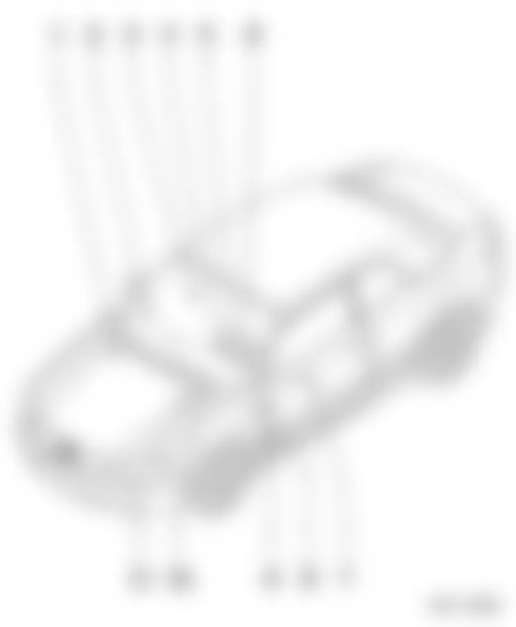
Location No. Description Refer to 1 Main Fuse Fig. 7 2 Connector station - Right A-pillar Fig. 13 3 Connector station - RF seat wiring Fig. 17 4 Relay panel (3-position) Fig. 9 5 Relay panel (9-position) at Vehicle Electrical System Control Module Fig. 12 6 Relay panel (4-position) with threaded connection Fig. 11 7 Connector station - LF seat wiring Fig. 17 8 Fuse panel Fig. 8 9 Connector station - Left A-pillar Fig. 15 10 Connector station E-Box Fig. 18 11 Relay panel (Carrier) E-Box Fig. 10 : For component locations refer to overview illustration, see Fig. 5
Audi S4 Quattro 2006 - COMPONENT IDENTIFICATION FUSES
WARNING: Never replace a fuse with one that has a higher amperage rating. A fuse with a too high amperage could damage the electrical part and cause a fire.
For access to fuse box, refer to Fig. 6.
Fig. 6: Audi S4 Quattro 2006 - Component Locations - Identifying Fuses Box Panel Cover

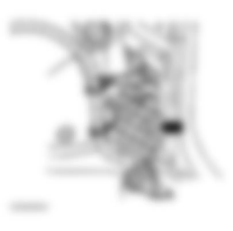
Audi S4 Quattro 2006 - Main Fuse (Engine Compartment)
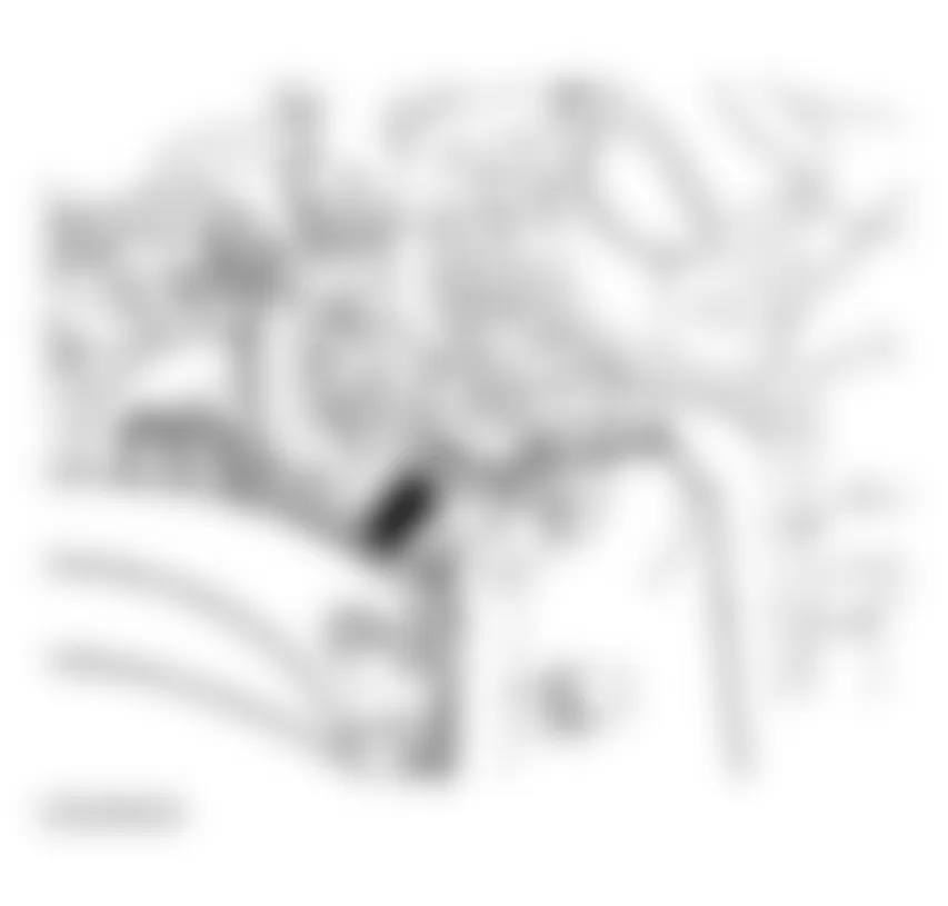
The main fuse is located on the battery positive post, the fuse is numbered "S88" and has an amperage rating of 150 amps. The battery is located in the plenum chamber on right side of engine compartment.
Fig. 7: Audi S4 Quattro 2006 - Component Locations - Locating Main Fuse
Audi S4 Quattro 2006 MAIN FUSE IDENTIFICATION (ENGINE COMPARTMENT - RIGHT SIDE)
Designation Amp Rating S88 - Strip fuse 150A
Audi S4 Quattro 2006 - Fuse Index Information (Passenger Compartment)

Audi S4 Quattro 2006 IDENTIFYING FUSES (INSTRUMENT PANEL - LEFT SIDE)
Fuse
No.Function/Component Amp Rating
(A) 1 E87 - A/C Control Head
J255 - Climatronic Control Module10A 2 W9 - Left Footwell Light
W10 - Right Footwell Light5A 3 Z20 - Left Washer Nozzle Heater
Z21 - Right Washer Nozzle Heater5A 4 J293 - Coolant Fan Control (FC) Control Module
J671 - Coolant Fan Control (FC) Control Module 25A 5 E272 - Function Selector Switch II
F189 - Tiptronic Switch
G266 - Oil Level Thermal Sensor
J401 - Navigation System with CD Drive Control Module
J446 - Parking Aid Control Module
J526 - Telephone Control Module
R36 - Telephone Transceiver10A 6 G65 - High Pressure Sensor
G238 - Sensor for air quality5A 7 E132 - Anti-Slip Control Switch
F36 - Clutch Pedal Switch
G85 - Steering Angle Sensor
J104 - ABS Control Module10A 8 J526 - Telephone/Telematics Control Module
R36 - Telephone Transceiver
R86 - Telephone Amplifier5A 9 J569 - Brake Booster Relay 15A 10 E102 - Headlamp Adjuster
J431 - Headlamp Range Control Module
V48 - Left Headlamp Beam Adjusting Motor
V49 - Right Headlamp Beam Adjusting Motor5A 11 Not used - 12 T16 - 16 pin connector, black, diagnostic connector 10A 13 J527 - Steering Column Electronic Systems Control Module 10A 14 F - Brake Light Switch
M9 - Left Brake Lamp
M10 - Right Brake Lamp
M25 - High-mount Brake Light10A 15 J285 - Instrument Cluster Control Module
J401 - Navigation System with CD Drive Control Module10A 16 E284 - Garage Door Opener Control Head
J530 - Garage Door Opener Control Module5A 17 J446 - Parking Aid Control Module
J502 - Tire Pressure Monitoring Control Module10A 18 Not used - 19 E23 - Fog Lamp Switch 10A 20 J344 - Right High-intensity Gas Discharge Lamp Control Module
M31 - Right Low Beam Headlamp
M32 - Right High Beam Headlamp
V49 - Right Headlamp Beam Adjusting Motor15A 21 J343 - Left High-intensity Gas Discharge Lamp Control Module
M29 - Left Low Beam Headlamp
M29 - Left High Beam Headlamp
V48 - Left Headlamp Beam Adjusting Motor15A 22 J386 - Drivers Door Control Module
J387 - Front Passenger's Door Control Module
V14 - Left Window Motor
V15 - Right Window Motor15A 23 Not used - 24 J393 - Comfort System Central Control Module 20A 25 J126 - Fresh Air Blower Control Module 30A 26 J9 - Rear Window Defogger Relay
E87 - A/C Control Head30A 27 J345 - Towing Recognition Control Module 30A 28 G6 - Transfer Fuel Pump (FP)
J538 - Fuel Pump (FP) Control Module20A 29 N - Ignition Coil
N70 - Ignition Coil 1 with Power Output Stage
N127 - Ignition Coil 2 with Power Output Stage
N128 - Ignition Coil 2
N158 - Ignition Coil 3
N291 - Ignition Coil 3 with Power Output Stage
N292 - Ignition Coil 4 with Power Output Stage
N323 - Ignition Coil 5 with Power Output Stage
N324 - Ignition Coil 6 with Power Output Stage
N325 - Ignition Coil 7 with Power Output Stage
N326 - Ignition Coil 8 with Power Output Stage20A 30 J245 - Convertible Top Control Module 30A 31 F4 - Back-Up Light Switch
F125 - Multi-Function Transmission Range (TR) Switch
G70 - Mass Air Flow (MAF) Sensor
J60 - Starting Interlock Relay
J217 - Transmission Control Module (1CM)
M16 - Left Back-Up Lamp
M17 - Right Back-Up Lamp
T16 - 16 Position Connector, Black Data Link Connector (DLC)
Y7 - Automatic Day/Night Interior Mirror15A 32 N30 - Cylinder 1 Fuel Injector
N31 - Cylinder 2 Fuel Injector
N32 - Cylinder 3 Fuel Injector
N33 - Cylinder 4 Fuel Injector
N83 - Cylinder 5 Fuel Injector
N84 - Cylinder 6 Fuel Injector
N85 - Cylinder 7 Fuel Injector
N86 - Cylinder 8 Fuel Injector20A 33 U1 - Cigarette lighter 15A U1 - Cigarette Lighter (from 2006 m.y.) 20A 34 G70 - Mass Air Flow (MAF) Sensor
J155 - Turbocharger (IC) Coolant Pump Control Module
N80 - Evaporative Emission (EVAP) Canister Purge Regulator
N112 - Secondary Air Injection (AIR) Solenoid Valve
N144 - Left Mount Solenoid Valve
N145 - Right Electro-Hydraulic Engine Mount Solenoid Valve
N156 - Intake Manifold Change-Over Valve
Z19 - Oxygen Sensor (O2S) Heater
Z29 - Oxygen Sensor (O2S) Heater 1 (behind Three Way Catalytic Converter (TWC))15A 35 U - Socket 30A U1 - Socket (from 2006 m.y.) 20A 36 J519 - Vehicle Electrical System Control Module 30A 37 J519 - Vehicle Electrical System Control Module
V11 - Headlamp Washer Pump30A 38 G303 - Radar Interior Monitoring Control Module 1
G305 - Radar Interior Monitoring Control Module 2
H12 - Alarm Horn
J393 - Comfort System Central Control Module15A 39 J401 - Navigation System with CD Drive Control Module
J402 - Operating Electronics, Navigation Control Module
J415 - Tuner for navigation/ TV
R - Radio
R12 - Amplifier
R94 - Navigation Interface
T8 - 8 Pin Connector, black, radio connector III20A 40 H2 - High Tone Horn
H7 - Low Tone Horn
J4 - Horn Relay25A 41 Not used 30A 42 J104 - ABS Control Module 25A 43 J220 - Motronic Engine Control Module (ECM)
N75 - Wastegate Bypass Regulator Valve
N205 - Valve 1 for camshaft adjustment
N208 - Valve 2 for camshaft adjustment15A 44 J215 - Climatronic Control Module
J216 - Right Rear Heated Seat Control Module30A J215 - Left Rear Heated Seat Control Module (from 2006 m.y.)
J216 - Right Rear Heated Seat Control Module (from 2006 m.y)35A Some of the equipment items listed are optional or only available on certain model configurations.
AUTOMATIC CIRCUIT BREAKERS:
The electric power windows and the electric seat adjusters are protected with Circuit breakers which reset automatically after the circuit overload has been corrected.
NOTE: Whenever replacing a fuse, always consult the sticker on the inside of the fuse panel cover. It contains the most up-to-date information regarding the fuse arrangement.
Audi S4 Quattro 2006 - RELAYS Relay Panel (3 Position) Dash Panel Driver's Side
For relay number, position number and circuits protected, see IDENTIFYING RELAYS (3 POSITION) DASH PANEL DRIVER'S SIDE) table. For fuse number, position number, amperage rating and circuits protected, see IDENTIFYING RELAYS (3 POSITION) DASH PANEL DRIVER'S SIDE table.
NOTE: The relay panel (3 position) carrier is located on the driver's side dash panel area on the right side. For fuse and relay positions within the panel, see Fig. 9.
Fig. 9: Audi S4 Quattro 2006 - Component Locations - Identifying Relay Carrier (3-Position)

Audi S4 Quattro 2006 IDENTIFYING RELAYS (3 POSITION) DASH PANEL DRIVER'S SIDE)
Position Socket Color Circuit Protected 2 Black J359 - Preheating Coolant , Low Heat Output Relay 3 Brown J360 - Preheating Coolant , High Heat Output Relay Note: The remaining items in the relay carrier are not used.
Audi S4 Quattro 2006 IDENTIFYING RELAYS (3 POSITION) DASH PANEL DRIVER'S SIDE
Position Socket Color Circuit Protected Amp Rating B Black S328 - Auxiliary Heater Fuse 2 60A C Green S126 - Auxiliary Heater Fuse 40A Note: The remaining items in the relay carrier are not used.
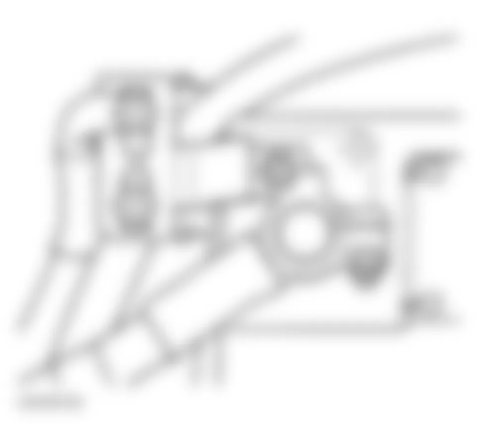
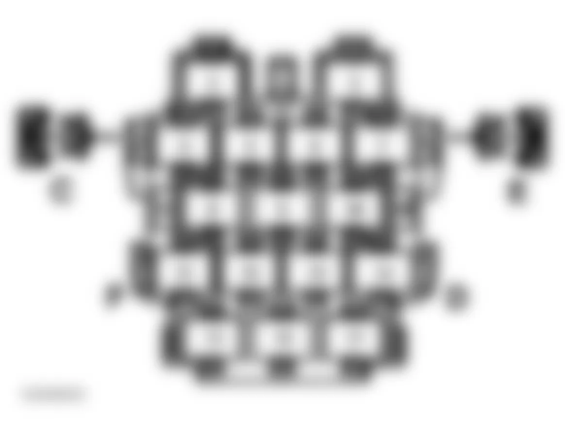
Audi S4 Quattro 2006 - Relay Carrier In Electronics Box, Plenum Chamber
For fuse and relay positions within the panel, see Fig. 10.
For relay number, position number and circuits protected, see the appropriate IDENTIFYING RELAYS table.
For fuse number, position number, amperage rating and circuits protected, see the appropriate IDENTIFYING FUSES table.
NOTE: The relay panel (4 position) carrier is located in electronics box, plenum chamber, in the left rear corner of the engine compartment.
Fig. 10: Audi S4 Quattro 2006 - Component Locations - Relay Panel (4 Position) In E-Box
Audi S4 Quattro 2006 - Relay Carrier E-Box (Gasoline Engine)
For identification of the relay panel 4 position carrier and it's layout, refer to Fig. 10.
Audi S4 Quattro 2006 IDENTIFYING RELAYS (RELAY CARRIER IN E-BOX - GASOLINE ENGINE)
Position No. Socket Color Circuit Protected 1 Black J60 - Starter Interlock Alarm System Relay 1.1 Red J151 - Coolant Circulation Pump Relay 2 Brown J299 - Secondary Air Injection (AIR) Pump Relay 3 Black J271 - Motronic (ECM) Power Supply Relay 3 Red J155 - Turbocharger (TC) Coolant Pump Relay 4 Blue J226 - Park/Nuetral Position (PNP) Relay J434 - Starter Lock/Clutch Pedal Switch Relay Note: The remaining items in the relay carrier are not used.
Audi S4 Quattro 2006 IDENTIFYING RELAYS (RELAY CARRIER IN E-BOX - GASOLINE ENGINE)
Position No. Socket Color Amp Rating Circuit Protected A Black 15A S282 - Engine Electronics Fuse B Black 40A S130- Secondary Air Injection (AIR) Pump fuse C Grey 15A S286 - Automatic Transmission After-Run Fuse Note: The remaining items in the relay carrier are not used.
Audi S4 Quattro 2006 - Relay Carrier E-Box (Diesel Engine*)
For identification of the relay panel 4 position carrier and it's layout, refer to Fig. 10.
Audi S4 Quattro 2006 IDENTIFYING RELAYS (RELAY CARRIER IN E-BOX - DIESEL ENGINE)
Position No. Socket Color Circuit Protected 1 Black J60 - Starter Interlock Alarm System Relay 1.2 Blue J17 - Fuel Pump (FP) Relay 2 Black J52 - Glow Plug Relay 3 Brown J317 - Power Supply (Terminal 30, B+) Relay 4 Black J226 - Park/Nuetral Position (PNP) Relay J434 - Starter Lock/Clutch Pedal Switch Relay : The remaining items in the relay carrier are not used.
*: Diesel engine - not for USA/CDN.
Audi S4 Quattro 2006 IDENTIFYING RELAYS (RELAY CARRIER IN E-BOX - DIESEL ENGINE)
Position No. Socket Color Amp Rating Circuit Protected A Black 15A S102 - Engine Control Module (ECM) Fuse B Black 60A S39 - Engine Glow Plug Fuse Strip C Grey 15A S286 - Automatic Transmission After-Run Fuse D Red 60A S189 - Fuse 2 For Glow Plugs E - - V274 - Control Module Cooling Fan F Red 60A S189 - Fuse 2 For Glow Plugs : Items D, E and F are in electronic box, plenum chamber.
: The remaining items in the relay carrier are not used.
*: Diesel engine - not for USA/CDN.
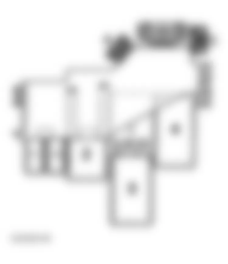
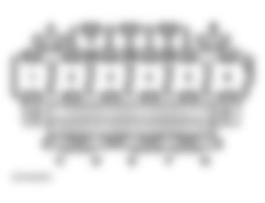
Audi S4 Quattro 2006 - Relay Panel (4-Position) With Threaded Connection
For fuse and relay positions within carrier, see Fig. 11. For relay number, position number and circuits protected, see RELAY IDENTIFICATION (RELAY PANEL (4-POSITION) WITH THREADED CONNECTION) table. For fuse number, position number, amperage rating and circuits protected, see FUSE IDENTIFICATION (RELAY PANEL (4-POSITION) WITH THREADED CONNECTION) table.
NOTE: The relay panel (4-position) carrier is located under driver's side of instrument panel.
Audi S4 Quattro 2006 RELAY IDENTIFICATION (RELAY PANEL (4-POSITION) WITH THREADED CONNECTION)
Position No. Socket Color Circuit Protected 3 White J662 - NG Engine Throttle Relay 1 (Driving school) 4 Blue J663 - NG Engine Throttle Relay 2 (Driving school) Note: The remaining items in the relay carrier are not used.
Audi S4 Quattro 2006 FUSE IDENTIFICATION (RELAY PANEL (4-POSITION) WITH THREADED CONNECTION)
Position No. Socket Color Amp Rating Circuit Protected B - - Optional Equipment, Repeller system E Black 40A S214 - Radiator After run Fuse G Black 40A
60AS42 - Coolant Fan Fuse
S42 - Coolant Fan Fuse H Brown 40A S123 - ABS Control Module Fuse 1 Note: The remaining items in the relay carrier are not used.
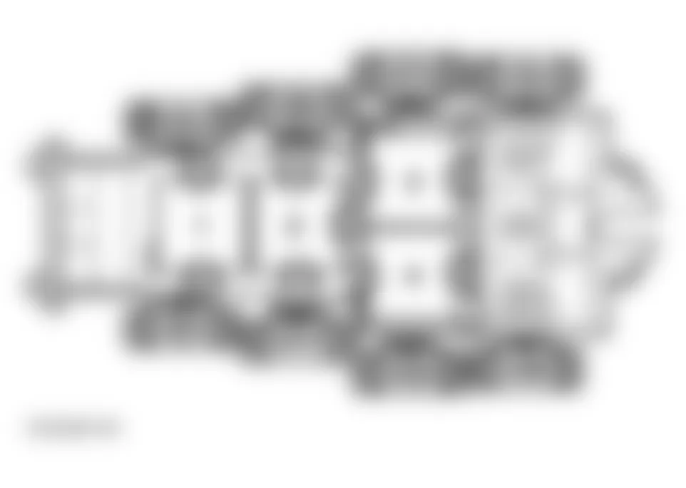
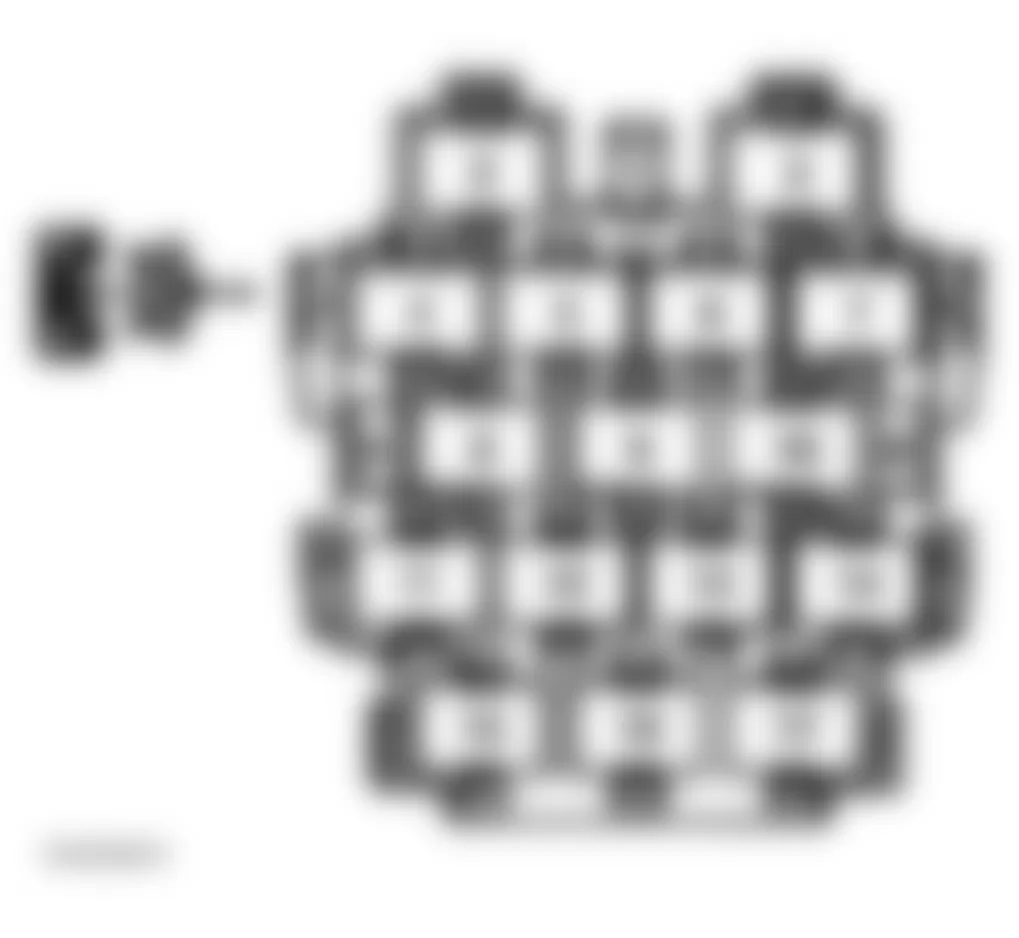
Audi S4 Quattro 2006 - Relay Panel (9-Position) At Vehicle Electrical System Control Module
For fuse and relay position within carrier, see Fig. 12. For relay number, position number and circuits protected, see RELAY IDENTIFICATION (RELAY PANEL (9-POSITION)) table. For fuse number, position number, amperage rating and circuits protected, see FUSE IDENTIFICATION (RELAY PANEL (9-POSITION)) table.
NOTE: The relay panel (9-position) is located behind instrument panel, driver's side, behind 3-position relay panel.
Audi S4 Quattro 2006 RELAY IDENTIFICATION (RELAY PANEL (9-POSITION))
Position No. Socket No. Circuit Protected 1 Green J17 - Fuel Pump (FP) Relay 2 Red J236 - Servotronic Control Module 3 Blue J4 - Horn Relay 4 Brown J569 - Brake Booster Relay 5 Purple J9 - Rear Window Defogger Relay 6 Black J59 - Load Reduction Relay Note: The remaining items in the relay carrier are not used.
Audi S4 Quattro 2006 FUSE IDENTIFICATION (RELAY PANEL (9-POSITION))
Position No. Socket Color Amp Rating Circuit Protected B Brown 40A S67 - Convertible Top Operation Fuse D Brown 30A S280 - Power Windows Fuse 2 E Red 30A S45 - Driver's Power Seat Adjustment Circuit Breaker 2 F Black 30A S37 - Power Windows Fuse G Green 30A S77 - Trailer (terminal 30, B+) Fuse Note: The remaining items in the relay carrier are not used.
Audi S4 Quattro 2006 - CONNECTOR STATION CONNECTOR STATION - RIGHT A PILLAR
The connector station is located at the right side footwell below the A-pillar trim. For pin and fuse position in connector station, see illustrations below.
Fig. 13: Audi S4 Quattro 2006 - Component Locations - Locating Connector Station (Right A Pillar)
Audi S4 Quattro 2006 FUSE IDENTIFICATION (CONNECTOR STATION - RIGHT)
Fuse Position Socket Color Amp Rating Circuit Protected E Black 30A S46 - Power Seat Black 10A S46 - Power Seat, Lumbar Adjustment. Note: The remaining items in the connector point are not used.
Audi S4 Quattro 2006 PIN IDENTIFICATION (CONNECTOR STATION - RIGHT)
Position No. Designation Component 13 T6p, 6 pin connector, Lilac Satellite radio 14 T6q, 6 pin connector, Lilac Satellite radio 15 T17c, 17 pin connector, Red Headlamp Note: The remaining items in the connector point are not used.
Audi S4 Quattro 2006 - CONNECTOR STATION - LEFT A PILLAR
The connector station is located at the left side footwell below the A-pillar trim. For pin and fuse position in connector station, see illustrations below.
Fig. 15: Audi S4 Quattro 2006 - Component Locations - Locating Connector Station (Left A Pillar)
Audi S4 Quattro 2006 PIN & FUSE IDENTIFICATION (CONNECTOR STATION - LEFT)
Position No. Designation Component 7 T6b - 6 pin connector, Black Servotronic 8 T10i - 10 pin connector, Blue Parking aid (where applicable) 12 T10k - 10 pin connector, White Auxiliary heater 13 T10c - 10 pin connector, Violet Wiper motor 14 T10d -10 pin connector, Grey Fan/compressor 15 T17b - 17 pin connector, Green Left headlight (connector 3) 16 T17a - 17 pin connector, Red Left headlight (connector 2) 17 T17 - 17 pin connector, Black Left headlight (connector 1) B T1a - 1 pin connector, Black Headlight washer system Note: The remaining items in the connector point are not used.
Audi S4 Quattro 2006 - CONNECTOR STATION - LF/RF SEAT WIRING
The connector stations are located under the passenger seat and under the driver seat. For pin position in connector station, see illustration below.
Fig. 17: Audi S4 Quattro 2006 - Component Locations - Connector Station - LF/RF Seat Wiring

Audi S4 Quattro 2006 PIN IDENTIFICATION (CONNECTOR STATION - RIGHT SEAT WIRING)
Position No. Designation Component 1 T3d - 3 pin connector, Yellow Side airbag 2 T10p - 10 pin connector, Red Supply 3 T6e - 6 pin connector, Green Seat heating 4 T8c - 8 pin connector Black Seat belt buckle
Audi S4 Quattro 2006 PIN IDENTIFICATION (CONNECTOR STATION - LEFT SEAT WIRING)
Position No. Designation Component 1 T3c - 3 pin connector, Yellow Side airbag 2 T10o - 10 pin connector, Red Supply 3 T6d - 6 pin connector, Green Seat heating 4 T8b - 8 pin connector Black Seat belt buckle
Audi S4 Quattro 2006 - CONNECTOR STATION E-BOX
The connector station is located In the electronic box in plenum chamber on left side of engine compartment. For pin position in connector station, see illustration below.
Fig. 18: Audi S4 Quattro 2006 - Component Locations - Identifying Connector Station E-Box

Audi S4 Quattro 2006 PIN IDENTIFICATION (CONNECTOR STATION - E-BOX)
Position No. Designation Component 1 T10 - 10 pin connector, Black Engine/Transmission (connector 2) 2 T10a - 10 pin connector, Brown Engine/Transmission (connector 3) 3 T17d - 17 pin connector, Red Engine/Transmission (connector 1) 6 T17e - 17 pin connector, White Engine/Transmission (connector 4) Note: The remaining items in the connector point are not used.
Audi S4 Quattro 2006 - FUSES - CIRCUIT PROTECTION
WARNING: Never replace a fuse with one that has a higher amperage rating. A fuse with a too high amperage could damage the electrical part and cause a fire.
For access to fuse box, refer to Fig. 19.
Fig. 19: Audi S4 Quattro 2006 - Component Locations - Identifying Fuses Box Panel Cover

Audi S4 Quattro 2006 - REPLACING A FUSE
A problem in the electrical system may be caused by a blown fuse.
- Switch off the ignition and the electrical component affected.
- Carefully pry the face cover off the instrument panel using the ignition key or a screwdriver. See Fig. 19.
- Check the fuse index to find out which fuse belongs to the component which has failed. See FUSES.
- Remove the blown fuse with the plastic clip provided. The clip is located on the holder in the fuse box.
- Replace a blown fuse (recognizable by the melted metal strip inside) with a fuse of the same amperage.
- Firmly snap the cover back onto the instrument panel face.
The various electrical circuits are protected by fuses. The fuses are clustered in a centralized unit. The unit is located behind the face panel at the end of the instrument panel.
Two spare fuses end a sticker identifying the fuses are located on the inside of the fuse box cover.
You are well advised to keep a supply of spare fuses in your vehicle. Fuses with the proper ampere ratings are available at your Audi dealer.
NOTE:
Audi S4 Quattro 2006 - FUSE - COLOR CODES
Identifying fuse color and ampere rating, refer to table below.
WARNING: Never replace a fuse with one that has a higher amperage rating. A fuse with a too high amperage could damage the electrical part and cause a fire.
Audi S4 Quattro 2006 IDENTIFYING FUSE BY COLOR
Current Rating Amperes Color 1A Black 3A Violet 5A Light Brown 7.5A Brown 10A Red 15A Blue 20A Yellow 25A White or Natural 30A Green 35A Green-Blue 40A Orange 50A Red