
Audi TT 2005 - 2005-06 ELECTRICAL Fuses & Circuit Breakers - TT Coupe & Roadster
Audi TT 2005 - IDENTIFICATION
WARNING: Vehicles are equipped with air bag supplemental restraint system. Before attempting any repairs involving steering column, instrument panel or related components, see AIRBAG SAFETY PRECAUTIONS in BODY INTERIOR article.
CAUTION: Before disconnecting battery, get radio code from customer. When battery is disconnected, vehicle computer and memory systems may lose memory data. Driveability problems may exist until computer systems have completed a relearn cycle.
Audi TT 2005 - ENGINE CODE
NOTE: Information for the 3.2L VR6 is included in this article. The 3.2L VR6 models use the Quattro? drive system and the Direct Shift Gearbox (DSG).
Engines are identified by a 3-letter code stamped on the engine. For engine code locations, see Fig. 1 and Fig. 2 . Engine codes are also located on the vehicle data plate.


Audi TT 2005 - FUSES - CIRCUIT PROTECTION
WARNING: Never replace a fuse with one that has a higher amperage rating. A fuse with a too high amperage could damage the electrical part and cause a fire.
For access to fuse box, refer to illustration below.
Fig. 3: Audi TT 2005 - Component Locations - Identifying Fuses Box Panel Cover

The individual circuits are protected by fuses. The fuse panel with the fuses is located on the left end face of the instrument panel behind a cover, other fuses and relays are located through out the vehicle for these components refer to COMPONENT IDENTIFICATION.
There is a plastic clip (fuse puller) in the holder of the fuse panel, which can be used to remove the fuses.
Two spare fuses and a sticker identifying the fuses are located on the inside of the fuse box cover.
Fuses with the proper ampere ratings are available at your Audi dealer.
NOTE:
AUTOMATIC CIRCUIT BREAKERS:
The electric power windows and the electric seat adjusters are protected with circuit breakers which reset automatically after the circuit overload has been corrected.
Audi TT 2005 - FUSE - COLOR CODES
Identifying fuse color and ampere rating, refer to table below.
WARNING: Never replace a fuse with one that has a higher amperage rating. A fuse with a too high amperage could damage the electrical part and cause a fire.
Audi TT 2005 IDENTIFYING FUSE BY COLOR
Current Rating Amperes Color 1A Black 3A Violet 5A Light Brown 7.5A Brown 10A Red 15A Blue 20A Yellow 25A White or Natural 30A Green 40A Orange
Audi TT 2005 - REPLACING A FUSE
A problem in the electrical system may be caused by a blown fuse.
- Switch off the ignition and the electrical component affected.
- Carefully pry the face cover off the instrument panel using the ignition key or a screwdriver. See Fig. 3.
- Check the fuse index to find out which fuse belongs to the component which has failed. See FUSE INDEX INFORMATION.
- Remove the blown fuse with the plastic clip (fuse puller) provided. The clip is located on the holder in the fuse box.
- Replace a blown fuse (recognizable by the melted metal strip inside) with a fuse of the same amperage.
- Firmly snap the fuse cover back onto the end of instrument panel face.
Audi TT 2005 - COMPONENT IDENTIFICATION FUSE INDEX INFORMATION
WARNING: Never replace a fuse with one that has a higher amperage rating. A fuse with a too high amperage could damage the electrical part and cause a fire.
- the appropriate wiring diagrams for applicable fuse usage and amperage ratings, for 2005 see POWER DISTRIBUTION and for 2006, see POWER DISTRIBUTION in SYSTEM WIRING DIAGRAMS article.
For fuse color/amperage identification, see FUSE - COLOR CODES table.
For access to fuse box, refer to Fig. 3, also see Fig. 4.
Audi TT 2005 - FUSE BOX - PASSENGER COMPARTMENT
Fig. 4: Audi TT 2005 - Component Locations - Identifying Fuse Box

Audi TT 2005 IDENTIFYING FUSES (PASSENGER COMPARTMENT)
Fuse
No.Rating
AmperageFunction/Component Wiring
IDTerminal 1 10A Z4 - Heated outside mirror, driver side
Z5 - Heated outside mirror, passenger side
Z20 Left Washer Nozzle Heater
Z21 - Right Washer Nozzle HeaterS1 75 2 10A E3 - Emergency Flasher Switch S2 75 3 5A W6 - Glove Compartment Light
J5 - Fog Light Relay
E87 - A/C Control HeadS3 58 4 5A X4 - Left License Plate Light
X5 - Right License Plate LightS4 58 5 7.5A E159 - Fresh Air/Recirculating Flap Switch
J151 - Coolant Circulation Pump Relay
J123 - Front Lamp Control Module
F47 - Brake Pedal SwitchS5 15 6 5A J429 - Control Module for central locking S6 15 7 10A T16 - Data Link Connector (DLC)
F4 - Back-Up Light Switch
E3 - Emergency Flasher Switch
G22 - Speedometer Vehicle Speed Sensor (VSS)S7 15 8 5A J412 - Operating Electronics and Telephone Control Module S8 15 9 5A J104 - ABS Control Module S9 75 10 10A 86s-Contact
J429 - Control Module for central locking
J285 - Control Module with indicator unit in instrument panel insertS10 86s 11 5A J285 - Control Module with indicator unit in instrument panel insert
G266 - Oil Level Thermal SensorS11 15 12 7.5A T16 - Data Link Connector
J412 - Operating Electronics and Telephone Control ModuleS12 30 13 10A F - Brake Light Switch S13 30 14 10A J429 - Control Module for central locking
M27 - Left Door Warning Light
M28 - Right Door Warning Light
E183 - Switch for passenger compartment monitoring
E150 - Driver's Interior Lock Switch
E188 - Switch for remote unlock, rear lidS14 30 15 5A J285 - Control Module with indicator unit in instrument panel insert
J217 - Transmission Control ModuleS15 30 16 10A J293 - Coolant Fan Control (FC) Control Module S16 30 17 15A J5 - Fog Light Relay
Daytime driving lightsS17 75 18 10A M32 - Right High Beam Headlight
J5 - Fog Light Relay
J285 - Control Module with indicator unit in instrumentS18 56 19 10A M30 - Left High Beam Headlight S19 56 20 15A V49 - Right Headlight Beam Adjusting Motor
E102 - Headlight Adjuster
V48 - Left Headlight Beam Adjusting Motor
J123 - Front Lamp Control ModuleS20 56 21 15A J123 - Front Lamp Control Module S21 56 22 5A J123 - Front Lamp Control Module
M3 - Right Parking Light
J285 - Control Module with indicator unit in instrument panel insertS22 58 23 5A J123 - Front Lamp Control Module
Ml - Left Parking Light
J285 - Control Module with indicator unit in instrument panel insertS223 57 24 20A J31 - Wiper/Washer Intermittent Relay
E22 - Windshield Wiper/Washer SwitchS224 75 25 25A E87 - A/C Control Head
J9 - Rear Window Defogger Relay
V2 - Fresh Air Blower
J126 - Control Module for fresh air blowerS225 75 26 25A E15 - Rear window defogger switch S226 75 27 30A J53 - Wind Deflector Control Module (Cabrio)
E278 - Wind Deflector Switch (Cabrio)S227 75 28 20A G6 - Fuel Pump (FP) S228 87 29 15A J220 - Motronic Engine Control Module (ECM) S229 15 30 - Not used - - 31 5A
20AJ492 - All-Wheel Drive Control Module
J217 - Transmission Control ModuleS231 15 32 10A N... - Fuel Injectors S232 87 33 20A
30A (1)J31 - Wiper/Washer Intermittent Relay S233 30 34 10A N75 - Wastegate Bypass Regulator
N205 - Valve 1 for camshaft adjustment
N249 - Recirculating valve for turbochargerS234 87 35 - Not used - - 36 15A E23 - Fog Light Switch S236 75 37 20A J220 - Motronic Engine Control Module (ECM)
J271 - Motronic Engine Control Module (ECM) Power Supply RelayS237 30 38 15A J429 - Control Module for central locking
H8 - Alarm HornS238 30 39 15A E3 - Emergency flasher system S239 30 40 20A J4 - Horn Relay S240 30 41 15A U1 - Cigarette lighter S241 30 42 20A R - Radio
R12 - Amplifier
R146 - Satellite RadioS242 30 43 10A
15A (2)N112 - Secondary Air Injection (AIR) Solenoid Valve
J299 - Secondary Air Injection (AIR) Pump Relay
G70 - Mass Air Flow (MAF) Sensor
G235 - Exhaust Gas Temperature (EGT) Sensor 1S243 87 44 15A E94 - Drivers Heated Seat Adjuster
E95 - Front Passenger Heated Seat AdjusterS244 30
(1) From 2005 m.y.
(2) Applies to 3.2L Engine codes BHE & BPF.
Some of the equipment items listed are optional or only available on certain model configurations.
NOTE: Whenever replacing a fuse, always consult the sticker on the inside of the fuse panel cover. It contains the most up-to-date information regarding the fuse arrangement.
Audi TT 2005 - MAIN FUSE BOX/BATTERY - ENGINE COMPARTMENT
NOTE: For 1.8L models the main fuses are located at the battery in the engine compartment, for the 3.2L main fuses are located at the battery which is located in the trunk spare wheel well on left side. See Fig. 5 and Fig. 6.
For main battery fuse box, fuse identification, see MAIN BATTERY BOX - FUSE IDENTIFICATION. For fuse color/amperage identification, see FUSE - COLOR CODES table.
Fig. 5: Audi TT 2005 - Component Locations - Locating Main Battery Fuse Box


Audi TT 2005 - Main Fuse Box/Battery Fuses
- the appropriate wiring diagrams for applicable fuse usage and amperage ratings, for 2005 see POWER DISTRIBUTION and for 2006, see POWER DISTRIBUTION in SYSTEM WIRING DIAGRAMS article.
For fuse color/amperage identification, see FUSE - COLOR CODES table.
Fig. 7: Audi TT 2005 - Component Locations - Identifying Main Fuse Box/Battery Fuse Locations
Audi TT 2005 MAIN BATTERY BOX - FUSE IDENTIFICATION
Circuit No. Circuit Description Amperage Rating S131 Safety Fuse No. 1 - S132 Safety Fuse No. 2 - S133 Safety Fuse No. 3 - S134 Safety Fuse No. 4 - S138 Safety Fuse No. 5 - S162 No. 1 Fuse Bracket (Battery) - S163 No. 2 Fuse Bracket (Battery) - S164 No. 3 Fuse Bracket (Battery) -
Audi TT 2005 - RELAYS W-BOX RELAY CARRIER
For fuse and relay positions within carrier, see Fig. 8. For relay number, position number and circuits protected, see RELAY & FUSE IDENTIFICATION (W-BOX RELAY CARRIER).
- the appropriate wiring diagrams for applicable fuse usage and amperage ratings, for 2005 see POWER DISTRIBUTION and for 2006, see POWER DISTRIBUTION in SYSTEM WIRING DIAGRAMS article.
For fuse color/amperage identification, see FUSE - COLOR CODES table.
NOTE: W-Box Relay Carrier is in the left rear corner of engine compartment, behind brake fluid reservoir, under cover.
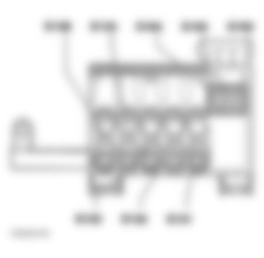
Fig. 8: Audi TT 2005 - Component Locations - Identifying W-Box Relay Carrier Fuses & Relays
Audi TT 2005 RELAY & FUSE IDENTIFICATION (W-BOX RELAY CARRIER)
Position Circuit No. Circuit Description 1 J299 Secondary Air Injector (AIR) Pump Relay 2 J271 Motronic Engine Control Module, Power Supply Relay 3 S279 Hydraulic Pump Relay Fuse 4 S130 Secondary Air Pump Fuse 5 N/A Not Used 6 N/A Not Used 7 S113 Control Module Fuse
(Automatic Transmission) 8 N/A Not Used 9 N/A Not Used
Audi TT 2005 - THIRTEEN FOLD RELAY PANEL
For fuse and relay position within carrier, see Fig. 9. For relay number, position number and circuits protected, see RELAY IDENTIFICATION (THIRTEEN FOLD RELAY PANEL) table. For fuse number, position number and circuits protected, see FUSE IDENTIFICATION (THIRTEEN FOLD RELAY PANEL) table.
- the appropriate wiring diagrams for applicable fuse usage and amperage ratings, for 2005 see POWER DISTRIBUTION and for 2006, see POWER DISTRIBUTION in SYSTEM WIRING DIAGRAMS article.
For fuse color/amperage identification, see FUSE - COLOR CODES table.
NOTE: Thirteen fold relay panel is located behind trim panel under driver's side of instrument panel.
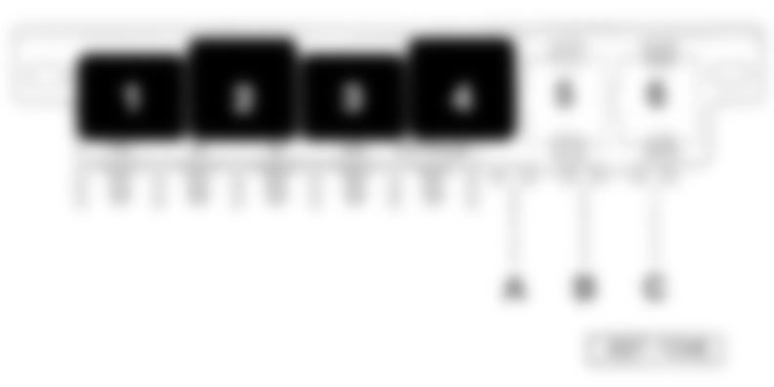
Fig. 9: Audi TT 2005 - Component Locations - Identifying Thirteen Fold Panel Components

Audi TT 2005 RELAY IDENTIFICATION (THIRTEEN FOLD RELAY PANEL)
Position No. Circuit No. Circuit Description 1 NA Not used 2 J123 Front Lamp Control Module 3 J123 Front Lamp Control Module 4 J5 Fog Light Relay 5 J207 Starting Interlock Relay 6 J5 Not used 7 J508 Brake Light Disable Relay (ESP)(not used from 2003 m.y.) 8 J453 Not used 9 J123 Not used 10 J9 Rear Window Defogger Relay 11 J207 Starting Interlock Relay 12 J351 Wind Deflector Control Module (Cabrio) 13 J151
J219Coolant Circulation Pump Relay
Back-Up Light Relay
Audi TT 2005 FUSE IDENTIFICATION (THIRTEEN FOLD RELAY PANEL)
Position No. Circuit No. Circuit Description 14 N/A Not Used 15 N/A Not Used 16 N/A Not Used 17 N/A Not Used 18 S187 Fuse for differential lock (Haldex Coupling)(to 1999 m.y.)
Not used (from 2000 m.y.)
Audi TT 2005 - MICRO CENTRAL ELECTRIC PANEL
For relay position within panel, see Fig. 10. For relay number, position number and circuits protected, see RELAY IDENTIFICATION (MICRO CENTRAL ELECTRIC PANEL) and FUSE IDENTIFICATION (MICRO CENTRAL ELECTRIC PANEL) tables.
- the appropriate wiring diagrams for applicable fuse usage and amperage ratings, for 2005 see POWER DISTRIBUTION and for 2006, see POWER DISTRIBUTION in SYSTEM WIRING DIAGRAMS article.
For fuse color/amperage identification, see FUSE - COLOR CODES table.
NOTE: Micro central electric panel is located below shelf on left side.
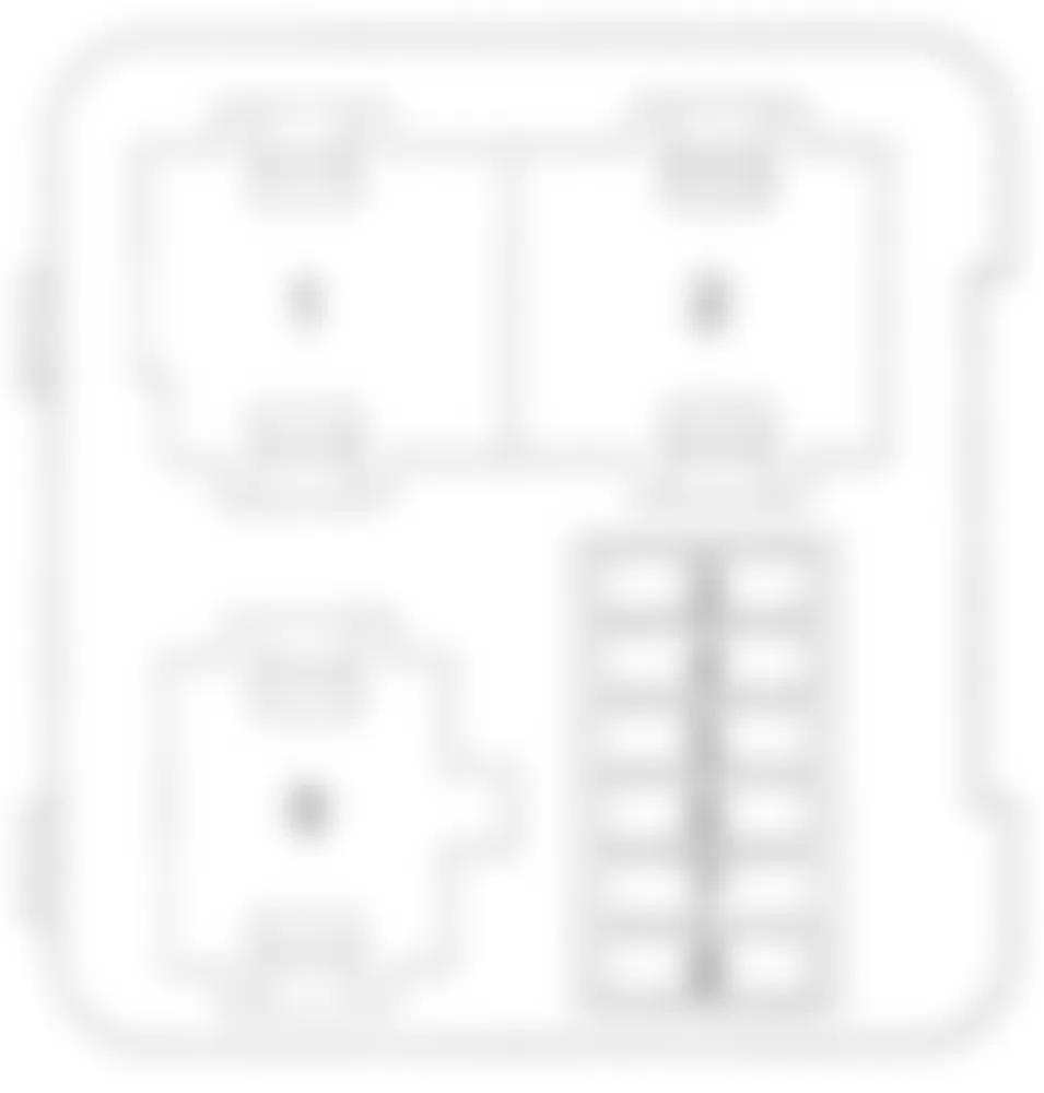
Fig. 10: Audi TT 2005 - Component Locations - Identifying Micro Central Electric Components
Audi TT 2005 RELAY IDENTIFICATION (MICRO CENTRAL ELECTRIC PANEL)
Position No. Circuit No. Circuit Description 1 J4 Horn Relay 2 J59 Load Reduction Relay 3 NA Not used 4 J17 Fuel Pump Relay 5 J31 Wiper/Washer Intermittent Relay 6 J31 Wiper/Washer Intermittent Relay
Audi TT 2005 FUSE IDENTIFICATION (MICRO CENTRAL ELECTRIC PANEL)
Position No. Circuit No. Circuit Description A S67 Convertible top Operation Fuse B S279 Hydraulic Pump Relay Fuse C S326 Power Window Circuit Breaker