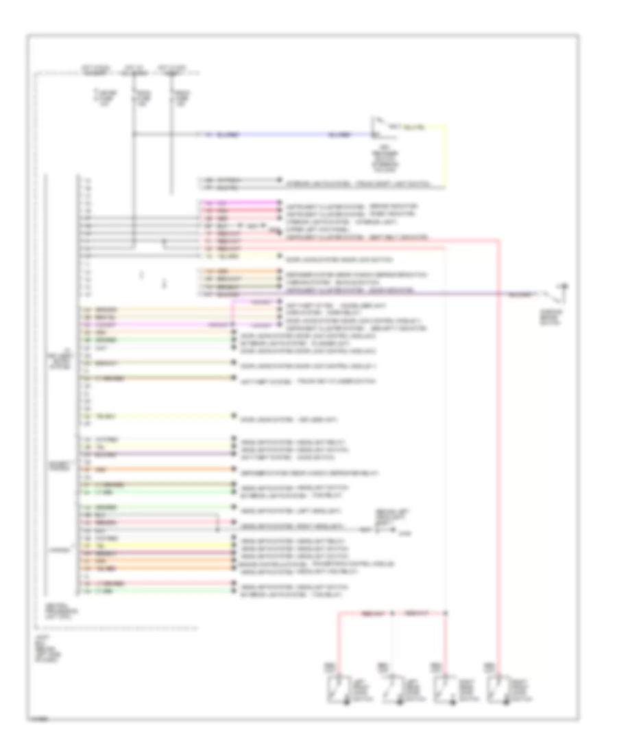
BODY COMPUTER
Body Computer Wiring Diagrams for Mazda 626 DX 1998
List of elements for Body Computer Wiring Diagrams for Mazda 626 DX 1998:
- (behind left headlight) jc-01
- (brake indicator)
- (buckle switch)
- (door indicator)
- (flasher unit)
- (headlight high relay)
- (headlight relay)
- (headlight switch)
- (hood switch)
- (horn relay)
- (immobilizer unit)
- (interior light)
- (keyless unit)
- (left headlight)
- (powertrain control module)
- (r-def indicator)
- (right headlight)
- (seat belt indicator)
- (security indicator)
- (tns relay)
- (trunk compt light switch)
- (trunk key cylinder switch)
- (upper left kick panel)
- 10i
- Anti-theft system
- Anti-theft sytem
- Canada
- Central processing unit (cpu)
- Defogger system (rear window defroster relay)
- Defogger system (rear window defroster switch)
- Door locks system
- Door locks system (door lock control module 1)
- Door locks system (door lock control module 2)
- Door locks system (door lock switch)
- Engine controls system
- Except canada
- Exterior lights system
- G106
- G200
- Headlights system
- Horn system
- Hot at all times
- Hot in acc & run
- Hot in run & start
- Instrument cluster system
- Interior lights system
- Joint box (behind left side of dash)
- Key reminder switch (steering column)
- Left front door switch
- Left rear door switch
- Meter fuse 10a
- Parking brake switch
- Pnk
- Radio fuse 15a
- Red
- Right front door switch
- Right rear door switch
- Room fuse 15a
- W/ keyless entry system
- Warning system
 Русский