BODY COMPUTER
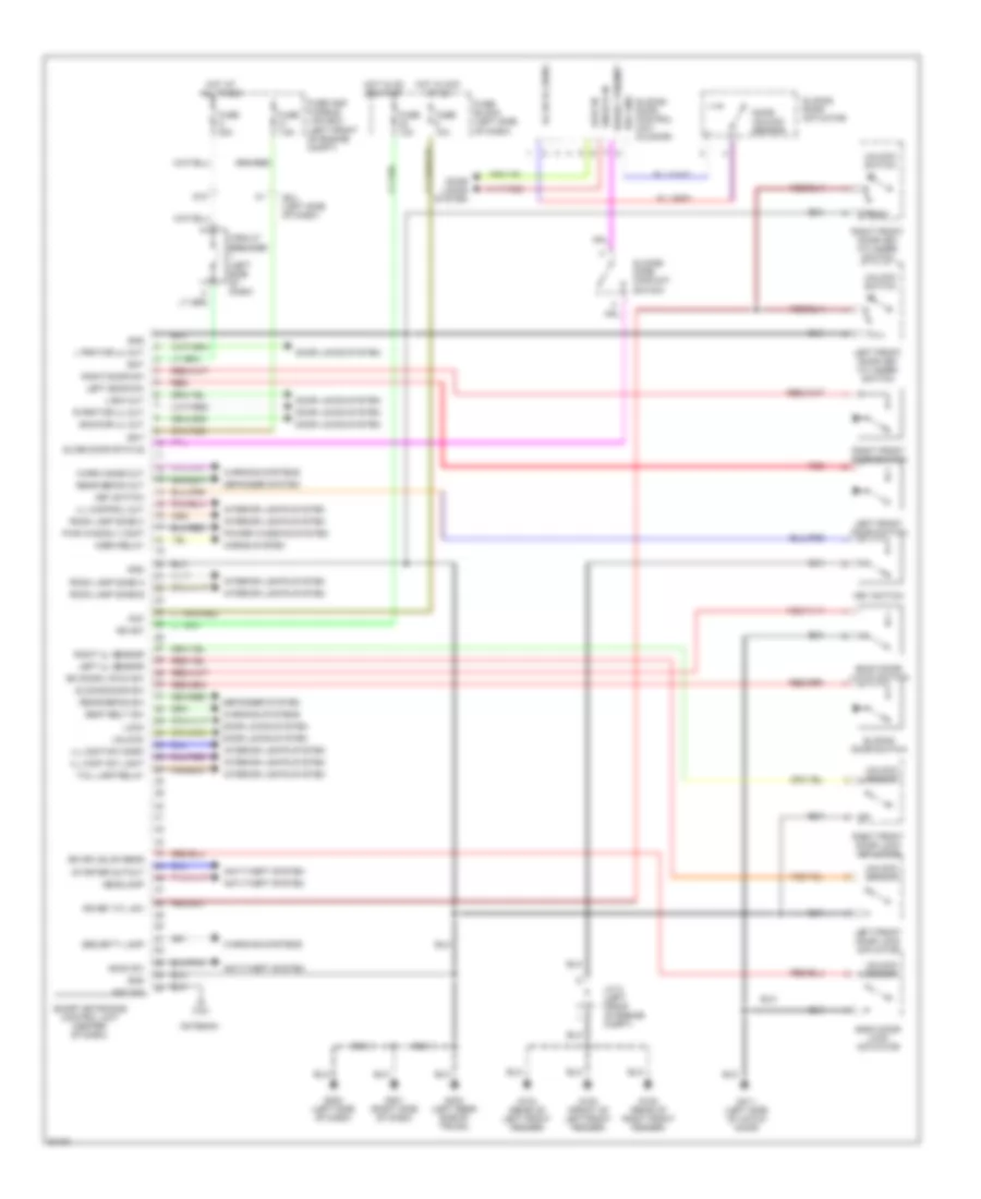
Smart Entrance Control Unit Wiring Diagram for Nissan Quest GXE 1997
List of elements for Smart Entrance Control Unit Wiring Diagram for Nissan Quest GXE 1997:
- Acc
- Ant sig
- Antenna
- Anti-theft system
- Back door latch switch
- Back door lock actuator
- Back dr ul out
- Bat
- Bk door latch sw
- Bk dr unlck sens
- Circuit breaker (left side of dash)
- D10
- Defogger system
- Door locks system
- Door unlock sensor
- Dr key cyl sw
- Full
- Fuse 10a
- Fuse 7.5a
- Fuse a 30a
- Fuse and fusible link box (left front of engine compt)
- Fuse block (left side
- G100 (front of left front fender)
- G104 (rear of left front fender)
- G105 (rear of right front fender)
- G201 (right side of dash)
- G202 (left side of dash)
- G404 (left rear side of trunk)
- G411 (left side of hatch door)
- Gnd
- Headlamp
- Hood sw
- Horn relay
- Horns system
- Hot at all times
- Hot in acc or on
- Hot in on or start
- Ign sw
- Ill cont sw dark
- Ill cont sw light
- Ill control out
- Interior lights system
- J/c 2 (left front of engine compt)
- Key switch
- L frnt dr ul out
- Left door sw
- Left front door key cylinder switch
- Left front door lock actuator
- Left front door switch
- Left ul sensor
- Lock
- Lock in
- Lock out
- Of dash)
- Power windows system
- Pwr wind rly cont
- R frnt dr ul out
- Rear defog out
- Rear defog sw
- Red
- Ref gnd
- Right door sw
- Right front door key cylinder switch
- Right front door lock actuator
- Right front door switch
- Right ul sensor
- Room lamp zone a
- Room lamp zone b
- Room lamp zone c
- Seat belt sw
- Security lamp
- Serial trnsmit
- Sl dr ul sens
- Slide door status
- Sliding door actuator
- Sliding door contact switch
- Sliding door control unit (in door)
- Sliding door sw
- Sliding door switch
- Smart entrance control unit (center of dash)
- Smj (left side of dash)
- Starter cutout
- Tail lamp relay
- Unlock
- Unlock in
- Unlock sensor
- Unlock switch
- Warn chime out
- Warniing systems
- Warning systems
 English