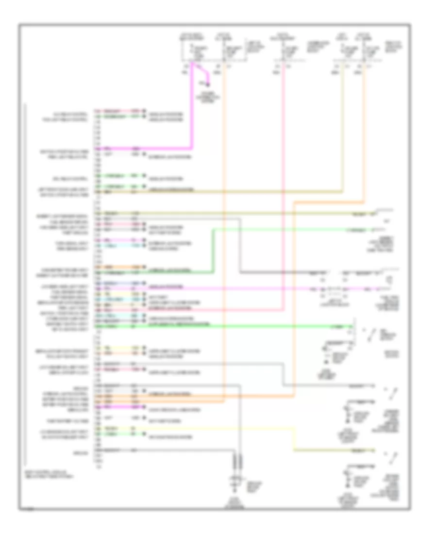
BODY COMPUTER
Body Computer Wiring Diagrams for Oldsmobile Cutlass GL 1999
List of elements for Body Computer Wiring Diagrams for Oldsmobile Cutlass GL 1999:
- A/c bfc fuse 10a
- A/c switch request input
- A10
- A11
- A12
- Air conditioning system
- Alc relay control
- Ambient lght snsr sig 5v ref
- Ambient light sensor (on top of dash trim pad)
- Ambient light sensor signal
- Anti-theft
- Anti-theft system
- B10
- B11
- B12
- Battery positive voltage
- Bfc batt fuse 10a
- Body control module (below right side of dash)
- Computer data lines system
- Cruise fuse 10a
- Drl relay control
- Engine coolant level switch (on engine coolant surge tank)
- Exterior lights system
- Fog light relay control
- Fog light switch input
- Fuel sensor return
- Fuel sensor signal
- Fuel tank module (under rear of vehicle)
- G100 (left front of engine compt)
- G125 (front of engine)
- G202 (left side of dash)
- Ground
- Ground splice pack
- Headlights system
- High beam headlight input
- Hot at all times
- Hot in accy, run or start
- Hot in run
- Hot in run or start
- Ignition 0 positive voltage
- Ignition 1 positive voltage
- Ignition 3 positive voltage
- Ignition switch
- Inadvertent power input
- Instrument cluster system
- Int lps fuse 10a
- Interior lights control
- Interior lights system
- Ipc/bfc acc fuse 10a
- Key in ignition input
- Key warning switch
- Left front door ajar input
- Left i/p junction block
- Low beam headlight input
- Low engine coolant input
- Low washer solvent input
- Other door ajar input
- Park brake input
- Park light input
- Park light relay ctrl
- Pnk
- Power distribution system
- Right i/p junction block
- Seat belt switch input
- Serial data
- Serial data spi clock
- Serial data spi data receive
- Serial data spi data transmit
- Theft battery voltage
- Theft ground
- Theft sensor signal
- Turn signal input
- Underhood junction block
- Warning system
- Warning systems system
- Washer solvent level sensor (inside left front fender)
 English