BODY CONTROL MODULES
Comfort System Central Control Module Wiring Diagram for Audi Q7 3.0 TDI 2012

List of elements for Comfort System Central Control Module Wiring Diagram for Audi Q7 3.0 TDI 2012:
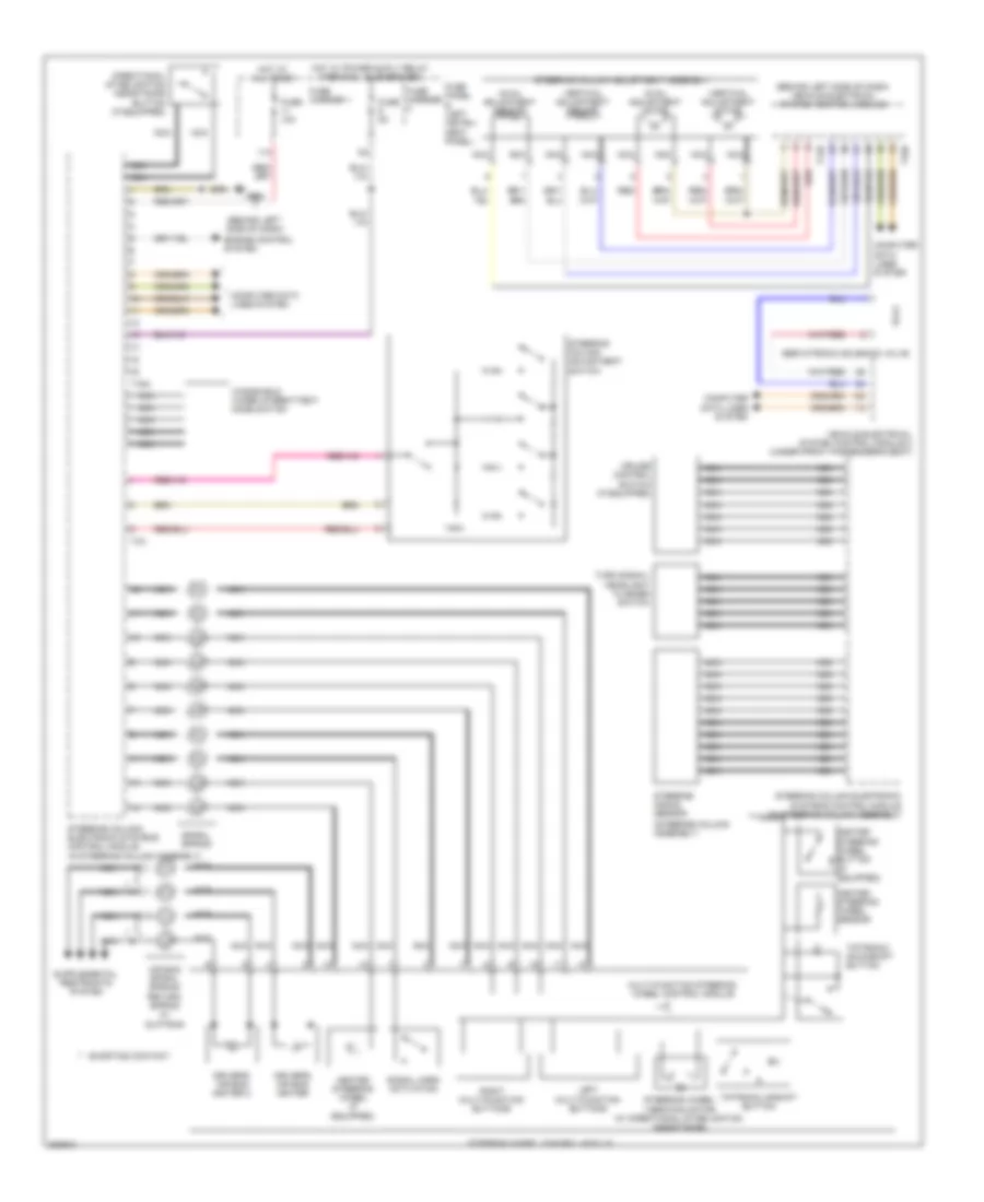
Steering Column Electronic Systems Control Module Wiring Diagram for Audi Q7 3.0 TDI 2012
List of elements for Steering Column Electronic Systems Control Module Wiring Diagram for Audi Q7 3.0 TDI 2012:
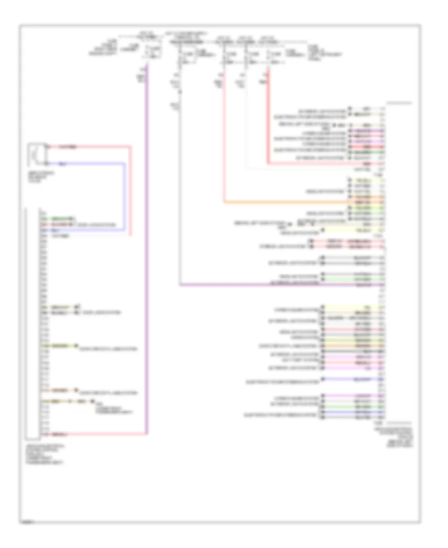
Vehicle Electrical System Control Module Wiring Diagram for Audi Q7 3.0 TDI 2012
List of elements for Vehicle Electrical System Control Module Wiring Diagram for Audi Q7 3.0 TDI 2012: