BODY CONTROL MODULES
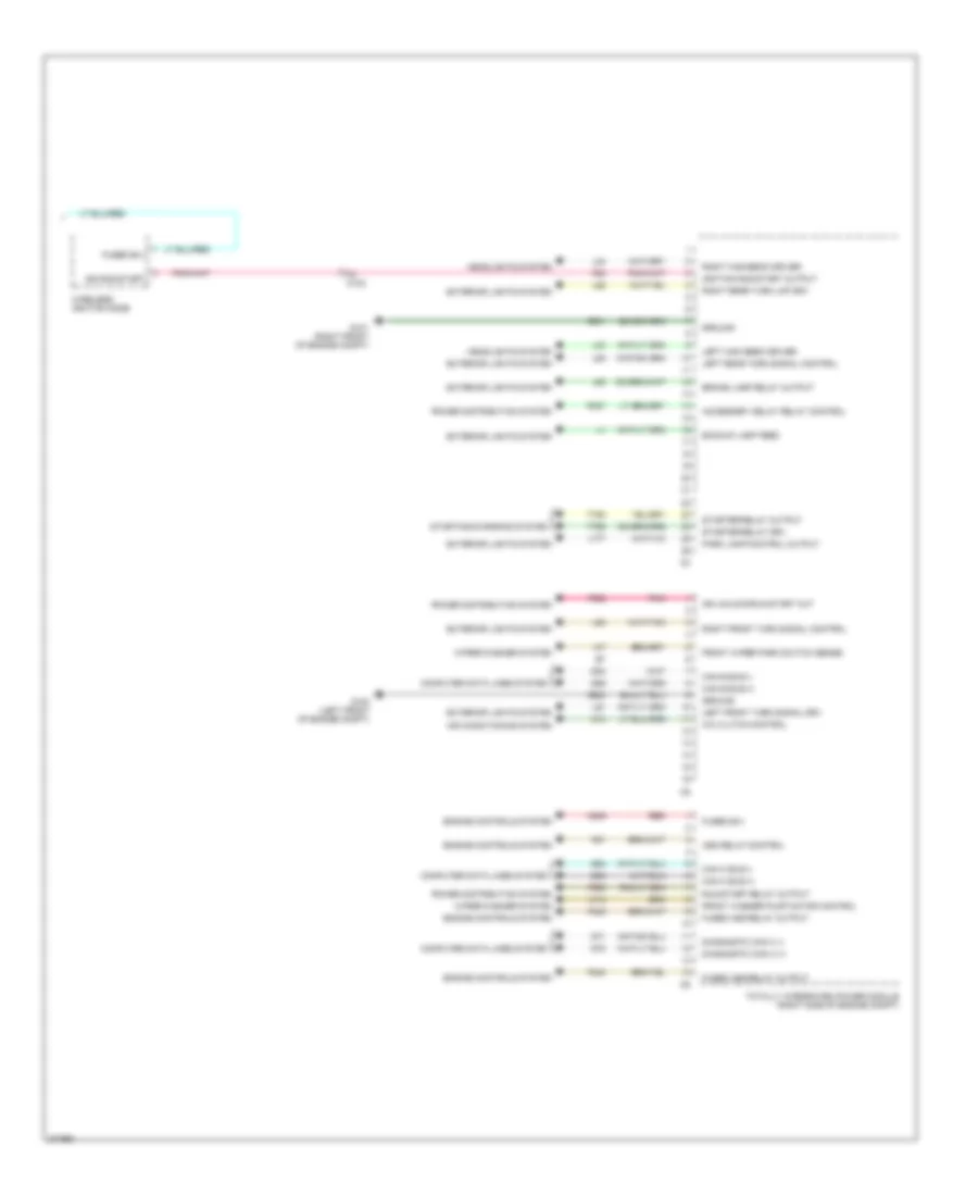
Body Control Modules Wiring Diagram (1 of 2) for Dodge Challenger R/T Plus 2011

List of elements for Body Control Modules Wiring Diagram (1 of 2) for Dodge Challenger R/T Plus 2011:
Body Control Modules Wiring Diagram (2 of 2) for Dodge Challenger R/T Plus 2011
List of elements for Body Control Modules Wiring Diagram (2 of 2) for Dodge Challenger R/T Plus 2011: