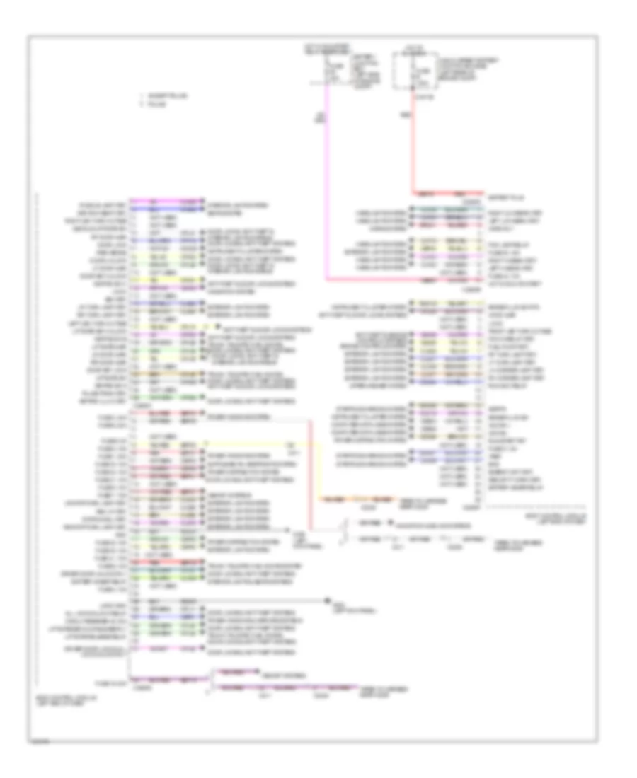
BODY CONTROL MODULES
Body Control Module Wiring Diagram (1 of 2) for Ford Explorer XLT 2014

List of elements for Body Control Module Wiring Diagram (1 of 2) for Ford Explorer XLT 2014:
- (not used)
- Acc
- Acc/run
- Air conditioning & headlights systems
- Air conditioning system
- Anti-theft system
- Autolamp sensor input
- Back lighting led (fet)
- Body control module (left end of dash)
- Bpp
- Bsi (fet)
- C2280a
- C2280b
- C299
- Cbp31
- Cbp35
- Cbp36
- Cbp37
- Cbp38
- Cbp41
- Cbp42
- Ccb08
- Cdc30
- Cdc33
- Cdc34
- Cdc35
- Cet53
- Cls32
- Clutch input
- Computer data lines system
- Cpk35
- Cpk36
- Crh04
- Door locks & anti-theft systems
- Epats rx
- Epats tx
- Except police
- Exterior lights system
- Fog lamp relay
- Fuse 11, 10a
- Fuse 23, 15a
- Fuse 24, 15a
- Fuse 26, 5a
- Fuse 27, 20a
- Fuse 28, 15a
- Fuse 29, 20a
- Fuse 31, 5a
- Fuse 32, 15a
- Fuse 34, 10a
- Fuse 35, 5a
- Fuse 36, 10a
- Fuse 37, 10a
- Fuse 38, 10a
- Fuse 41, 7.5a
- Fuse 42, 5a
- Fuse 43, 10a
- Fuse 44, 10a
- Fuse 45, 5a
- Fuse 46, 10a
- Fuse 9, 10a
- Generic function module (police) (lower right side of dash)
- Hazard sw
- Horn relay
- Horns system
- Hot at all times
- Ignition switch (w/o intelligent access)
- Interior lighting (fet)
- Interior lights system
- Key in
- Lin 01
- Lin 04
- Mirrors & power tops systems
- Ms can +
- Ms can -
- Navigation & sound systems
- Off
- Police
- Power distribution system
- Red
- Ripcord security
- Run
- Run/start
- S201
- S220
- Sbp09
- Sbp11
- Sbp23
- Sbp24
- Sbp26
- Sbp27
- Sbp28
- Sbp29
- Sbp46
- Seats system
- Shift interlock system
- Start
- Start/stop 1
- Start/stop 2
- Starting/charging system
- Strt/stop (led) fet
- Vbatt
- Vdb06
- Vdb07
- Vdn01
- Vlf14
- Vln04
- Vln33
- Vrt23
- Vrt24
- Warning systems
- White light (fet)
Body Control Module Wiring Diagram (2 of 2) for Ford Explorer XLT 2014
List of elements for Body Control Module Wiring Diagram (2 of 2) for Ford Explorer XLT 2014:
- (not used)
- 3rd row seat (fet)
- All lock/unlock relay
- Anti-theft & door locks systems
- Anti-theft & engine controls systems engine controls system
- Battery junction box (left side of engine compt)
- Battery plus
- Battery saver relay
- Bcs
- Body control module (left end of dash)
- Brake fluid sw
- Brake fluid sw rtn
- Bsi (fet)
- C1617b
- C211
- C2238
- C2280c
- C2280d
- C2280e
- C2280f
- C2280g
- Cbb94
- Cbp01
- Cbp30
- Cbp32
- Cbp33
- Cbp34
- Cbp40
- Cdc55
- Cdc64
- Ce226
- Ce436
- Circuit breaker 48, 30a
- Clf02
- Clf03
- Clf04
- Clf05
- Clf06
- Clf07
- Clf12
- Cln09
- Cln25
- Cls18
- Cls19
- Cls21
- Cls23
- Cls24
- Cls25
- Cls28
- Cls52
- Cmc19
- Cmc25
- Computer data lines system
- Cpk19
- Cpk23
- Cpk28
- Cpk29
- Cpk30
- Cpk31
- Cpl11
- Cpl25
- Cpl26
- Cpl31
- Cpl36
- Cpl39
- Cpl45
- Cpl51
- Cpl52
- Cpl58
- Cpl74
- Cpl84
- Cps48
- Decklid/liftgate sw
- Door key lock
- Door key unlock
- Door lock
- Door locks & anti-theft systems
- Door locks, anti-theft & interior lights systems
- Door locks, anti-theft & interior lights systems door locks & anti-theft systems
- Door unlock
- Driver door lock & all lock/unlock rly
- Driver door unlock rly
- Energy mgt (fet)
- Except police
- Exterior lights system
- Fog lamp relay
- Front led turn outage
- Fuel pump (fet)
- Fuse 1, 30a
- Fuse 19, 20a
- Fuse 2, 15a
- Fuse 21, 10a
- Fuse 3, 30a
- Fuse 30, 15a
- Fuse 30a
- Fuse 31, 5a
- Fuse 32, 15a
- Fuse 33, 10a
- Fuse 34, 10a
- Fuse 4, 10a
- Fuse 40, 10a
- Fuse 41, 7.5a
- Fuse 43, 10a
- Fuse 5, 20a
- Fuse 6, 5a
- Fuse 7, 7.5a
- Fuse 8, 10a
- Fuse 9, 10a
- Fuse b 100a
- G300 (left kick panel)
- Gd233
- Gnd
- Headlights system
- High current battery junction box (bjb) (left rear of engine compt)
- Hood ajar
- Horn rly
- Horns system
- Hot at all times
- Hot in run or start
- Hot w/ run/start relay energized
- Hs can +
- Hs can -
- Instrument cluster system
- Interior lights & seats systems
- Interior lights system
- Keypad illum (fet)
- Keypad sw a
- Keypad sw b
- Keypad sw c
- Ldc59
- Left hi beam (fet)
- Left led turn outage
- Left low beam (fet)
- Lf door ajar
- Lf turn lamp (fet)
- Lh corner lamp (fet)
- Liftgate ajar
- Liftgate key unlock
- Liftgate release relay
- Liftgate sw
- Liftgate/decklid release rly
- Lin 02
- Lin 03
- Logic gnd
- Lr door ajar
- Lr stop/turn lamp (fet)
- Lr turn lamp (fet)
- Memory systems
- Navigation & sound systems
- Navigation system
- Park brake
- Pcm wake up (fet)
- Police
- Power distribution system
- Power windows & mirrors systems
- Power windows system
- Puddle lamp (fet)
- Pulse train (fet)
- Rdc59
- Red
- Rev lp (fet)
- Rf door ajar
- Rf turn lamp (fet)
- Rh corner lamp (fet)
- Right hi beam (fet)
- Right led turn outage
- Right low beam (fet)
- Rmc19
- Rr door ajar
- Rr stop/turn lamp (fet)
- Rr turn lamp (fet)
- Run/acc relay
- Run/start fet
- Sbf16
- Sbp01
- Sbp02
- Sbp03
- Sbp05
- Sbp07
- Sbp09
- Sbp19
- Sbp21
- Sdc57
- Seats system
- Security horn (fet)
- Sigrtn
- Srh01
- Starting/charging system
- Stop/chmsl (fet)
- Taped to harness near c2238
- Trunk, tailgate, fuel doors system
- Trunk, tailgate, fuel doors, door locks & anti-theft systems
- Trunk, tailgate, fuel doors, door locks & anti-theft systems anti-theft & door locks systems
- Vdb04
- Vdb05
- Vdn03
- Vref
- Wiper/washer system
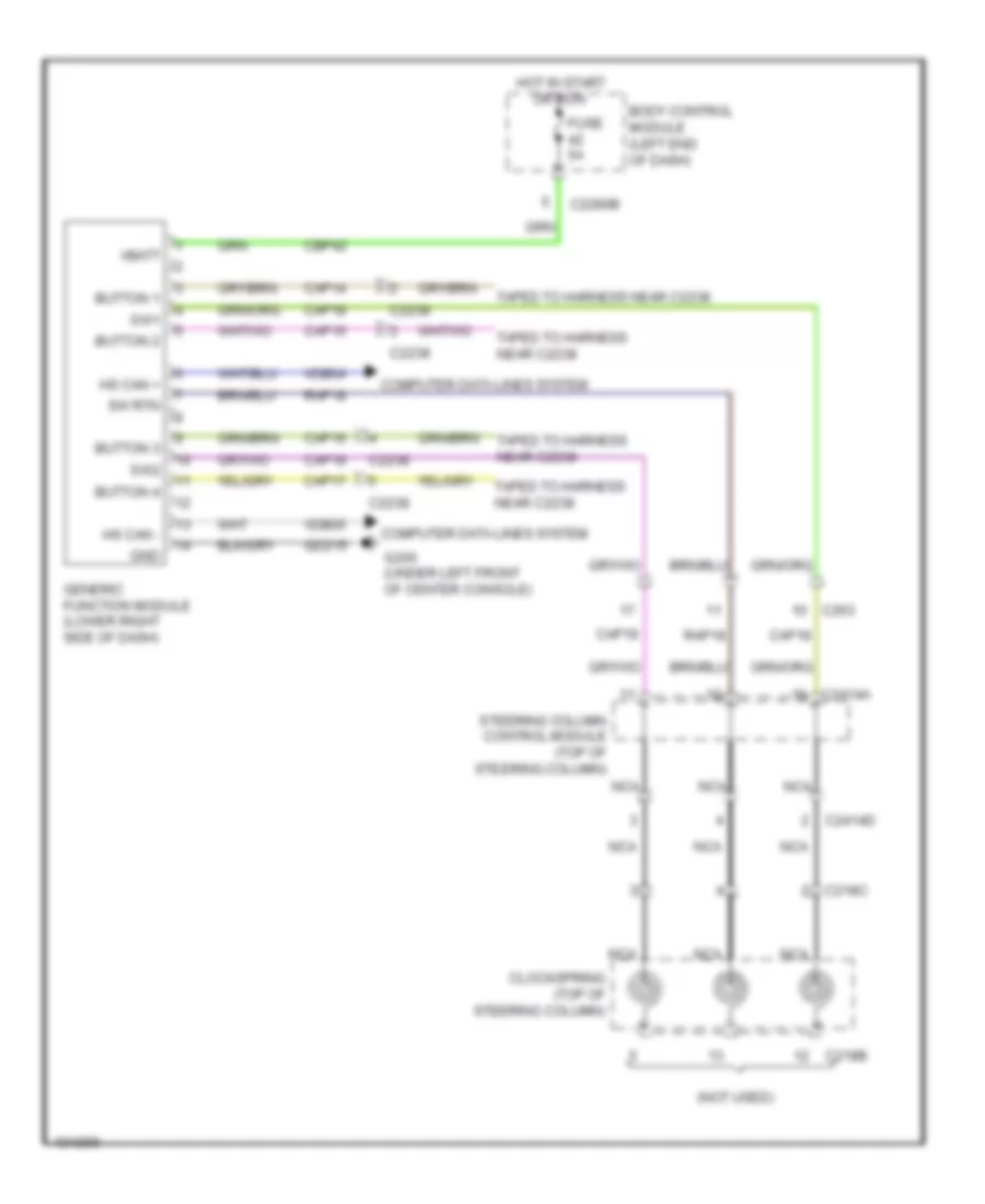
Generic Electronic Module Wiring Diagram for Ford Explorer XLT 2014
List of elements for Generic Electronic Module Wiring Diagram for Ford Explorer XLT 2014:
- (not used)
- Body control module (left end of dash)
- Button 1
- Button 2
- Button 3
- Button 4
- C218b
- C218c
- C2238
- C2280b
- C2414a
- C2414d
- C263
- Cap14
- Cap15
- Cap16
- Cap17
- Cap18
- Cap19
- Cbp42
- Clockspring (top of steering column)
- Computer data lines system
- Fuse 5a
- G200 (under left front of center console)
- Gd215
- Generic function module (lower right side of dash)
- Gnd
- Hot in start or run
- Hs can +
- Hs can -
- Nca
- Rap18
- Steering column control module (top of steering column)
- Sw rtn
- Sw1
- Sw2
- Taped to harness near c2238
- Vbatt
- Vdb04
- Vdb05