BODY CONTROL MODULES
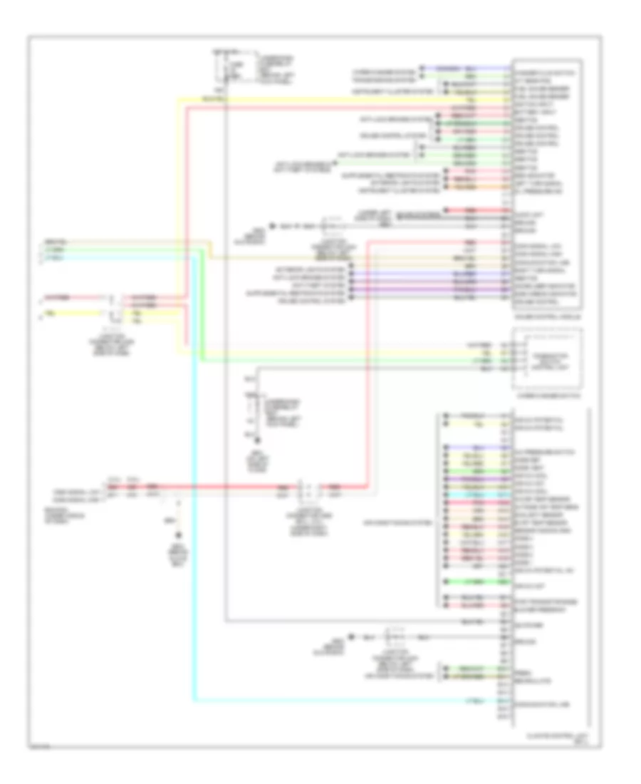
Body Control Modules Wiring Diagram, Except Hybrid (1 of 2) for Honda Accord DX 2005

List of elements for Body Control Modules Wiring Diagram, Except Hybrid (1 of 2) for Honda Accord DX 2005:
- (not used)
- (on left side of floor) g601
- Anti-theft system
- Atp-p
- Atp-r
- Back lt
- Battery input
- Ceiling light ctrl
- Check conn input
- Communication line
- Crtsy light ctrl
- D11
- Day lt
- Dlc (on lower left of dash, above the kick panel)
- Door locks
- Door locks system
- Door multiplex control unit
- Driver door lock
- E10
- E14
- E15
- Exterior lights system
- Exterior lights systems
- F12
- F14
- Fr as courtesy lt
- Fuse 10a
- Fuse 20a
- Fuse 7.5a
- G501 (behind left side of dash)
- G502 (behind left side of dash) shift interlock system
- Ground
- Ground distribution system
- H10
- H12
- H13
- H14
- Haz rly
- Hot at all times
- Hot in acc or on
- Hot in on or start
- I10
- Ig key lt
- Ig key sw
- Ignition input
- Ignition key light
- Ignition key switch
- Ignition key switch/ key light (except dx)
- Interior lights system
- Junction connector c404 (below left side of dash)
- K line
- K11
- K12
- Key sol
- Keyless receiver antenna
- Lf door switch
- Lr door switch
- Micu
- Multiplex control inspection connector
- N17
- N18
- N21
- N22
- N26
- N28
- N37
- P pin sw
- P10
- P11
- P12
- P13
- P14
- P15
- P16
- P17
- P18
- P19
- P20
- P21
- P22
- P23
- P24
- P25
- P26
- P27
- P28
- P29
- P30
- Pedal pos sw
- Power tops system
- Power window master switch
- Power windows
- Power windows system
- Q10
- Q11
- Q12
- Q13
- Q14
- Radio sw
- Red
- Relay control module
- Rem as lock
- Rem as unlock
- Rf door switch
- Rr door switch
- Seat belt input
- Shift interlock system
- Sil as unlock
- Sil ra unlock
- Sil rd unlock
- Sound systems
- Sunroof rly
- Trunk latch sw
- Trunk latch/light
- Trunk unlock
- Trunk,tailgate, fuel doors system
- Turn sig/haz rly
- Turn signal/ hazard relay
- Under-dash fuse/relay box (behind left kick panel)
- Under-hood fuse/relay box (on left rear corner of engine compt, forward of strut tower)
- Warning system
- X18
- X27
- X34
- X35
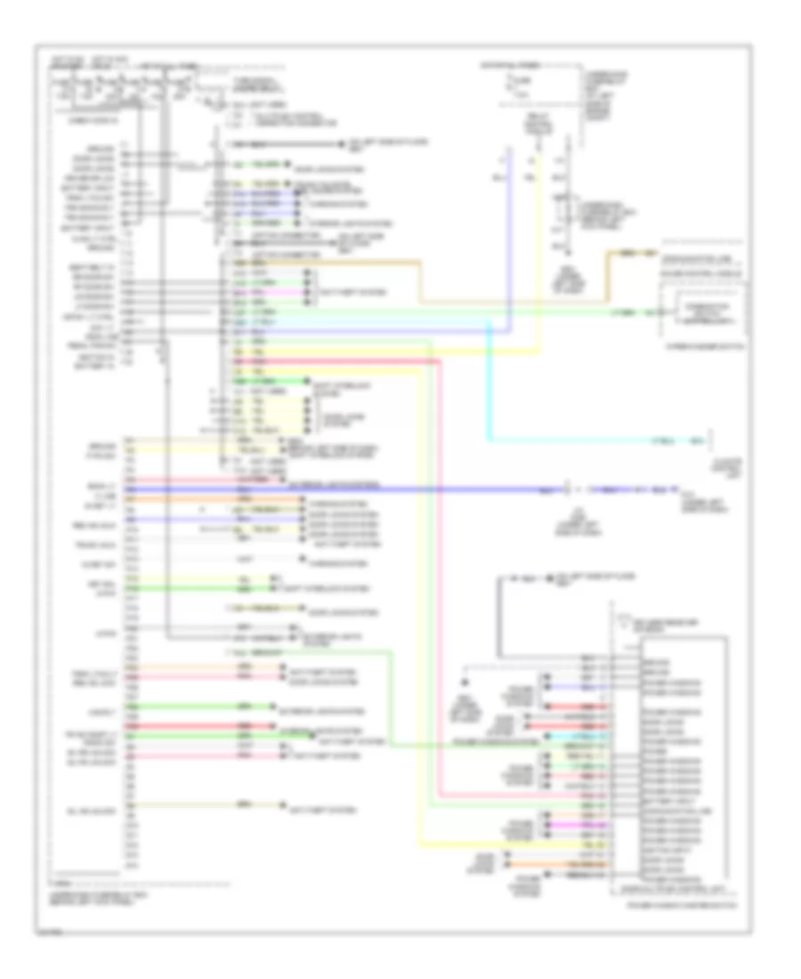
Body Control Modules Wiring Diagram, Except Hybrid (2 of 2) for Honda Accord DX 2005
List of elements for Body Control Modules Wiring Diagram, Except Hybrid (2 of 2) for Honda Accord DX 2005:
- (2.4l)
- (3.0l)
- (canada)
- (under left side of dash) g501
- A/c pressure switch
- A/t gear pos
- A10
- A11
- A12
- A13
- A14
- A15
- A16
- A17
- A18
- A19
- A20
- A21
- A22
- A26
- Abs/tcs
- Air conditioning system
- Air mix cool
- Air mix hot
- Air mix potential
- Air mix potential +5v
- Anti-lock brakes & anti-theft systems
- Anti-lock brakes system
- Anti-theft system
- Audio unit
- B10
- B11
- B12
- B13
- B14
- B15
- B16
- Battery input
- Blower feedback
- Climate control unit (ex-l)
- Combination switch control unit
- Comm signal high
- Comm signal low
- Communication line
- Cruise control
- Cruise control system
- E11
- E24
- Ecm/pcm (under middle of dash)
- Evap temp sensor
- Exterior lights system
- Fresh
- Fuel gauge sender
- Fuse 7.5a
- G503 (behind glove box)
- G601 (on left side of floor)
- Gauge control module
- Ground
- Hot in on
- Ig2 power
- Ignition input
- Immobilizer indicator
- In-car temp sensor
- Instrument cluster system
- Junction connector c404 (below left side of dash)
- Junction connector c405 (below left side of dash)
- Junction connector c555 (ex-l, 3.0l) (under right side of dash)
- Left turn signal
- Mode 1
- Mode 2
- Mode 3
- Mode 4
- Mode def
- Mode vent
- N20
- N42
- Oil pressure ind
- Outside air temp sens
- Pnk
- Pwr transistor base
- Recirculate
- Red
- Right turn signal
- Sensor common gnd
- Side airbag indicator
- Sound systems
- Srs indicator
- Sunlight sensor
- Transmissions system
- Under-dash fuse/relay box (behind left kick panel)
- Washer fluid switch
- Wiper/washer switch
- Wiper/washer system
Body Control Modules Wiring Diagram, Hybrid for Honda Accord DX 2005
List of elements for Body Control Modules Wiring Diagram, Hybrid for Honda Accord DX 2005:
- (not used)
- (on left side of floor) g601
- Anti-theft system
- Atp-p
- Atp-r
- B14
- Back lt
- Battery in
- Battery input
- Check conn in
- Climate control unit
- Clng lt ctrl
- Combination switch control unit
- Comm line
- Communication line
- Crtsy lt ctrl
- D11
- Day lt
- Dlc (under left side of dash)
- Door locks
- Door locks system
- Door multiplex control unit
- Driver dr lck
- E10
- E14
- E15
- Exterior lights system
- Exterior lights systems
- F12
- F14
- Fr as court lt
- Fuse 10a
- Fuse 20a
- Fuse 7.5a
- G501 (under left side of dash)
- G502 (behind left side of dash) shift interlock system
- Gauge control module
- Ground
- H10
- H12
- H13
- H14
- Haz rly
- Hot at all times
- Hot in acc or on
- Hot in on or start
- I10
- Ig key lt
- Ig key sw
- Ignition in
- Ignition input
- Interior lights system
- J/c c406 (under left side of dash)
- K line
- K11
- K12
- Key sol
- Keyless receiver antenna
- Lf door sw
- Lr door sw
- Micu
- Multiplex control inspection connector
- N17
- N18
- N22
- N26
- N28
- P pin sw
- P10
- P11
- P12
- P13
- P14
- P15
- P16
- P17
- P18
- P19
- P20
- P21
- P22
- P23
- P24
- P25
- P26
- P27
- P28
- P29
- P30
- Pedal pos sw
- Pnk
- Power
- Power window master switch
- Power windows
- Power windows system
- Q10
- Q11
- Q12
- Q13
- Q14
- Radio sw
- Red
- Relay control module
- Rem as lock
- Rem as unlk
- Rf door sw
- Rr door sw
- Seat belt in
- Shift interlock system
- Sil as unlock
- Sil ra unlock
- Sil rd unlock
- Trn sig/hz rly
- Trnk ltch sw
- Trnk ltch/lt
- Trunk unlk
- Trunk,tailgate, fuel doors system
- Turn signal/ hazard relay
- Under-dash fuse/relay box (behind left kick panel)
- Under-hood fuse/relay box (at left side of engine compt)
- Warning system
- Wiper/washer switch
- X18
- X27