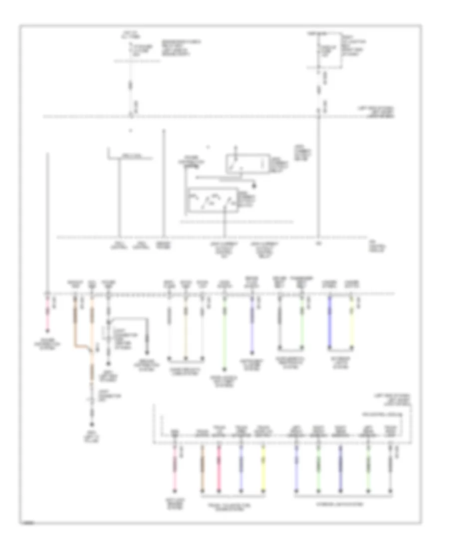
BODY CONTROL MODULES
Body Control Module Wiring Diagram for Hyundai Equus Signature 2014

List of elements for Body Control Module Wiring Diagram for Hyundai Equus Signature 2014:
Front Area Module Wiring Diagram for Hyundai Equus Signature 2014
List of elements for Front Area Module Wiring Diagram for Hyundai Equus Signature 2014:
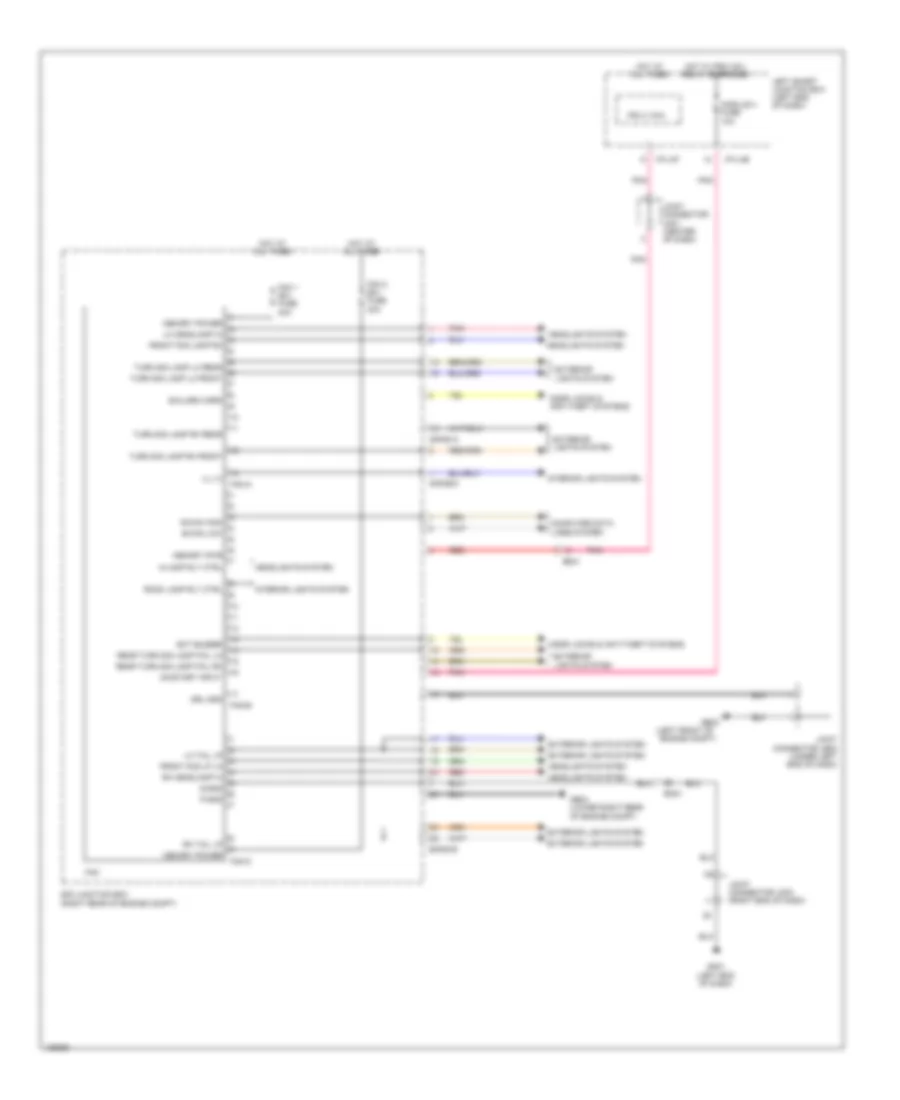
IPS Control Module Wiring Diagram for Hyundai Equus Signature 2014
List of elements for IPS Control Module Wiring Diagram for Hyundai Equus Signature 2014: