BODY CONTROL MODULES
Body Control Modules Wiring Diagram for Mercury Marauder 2003
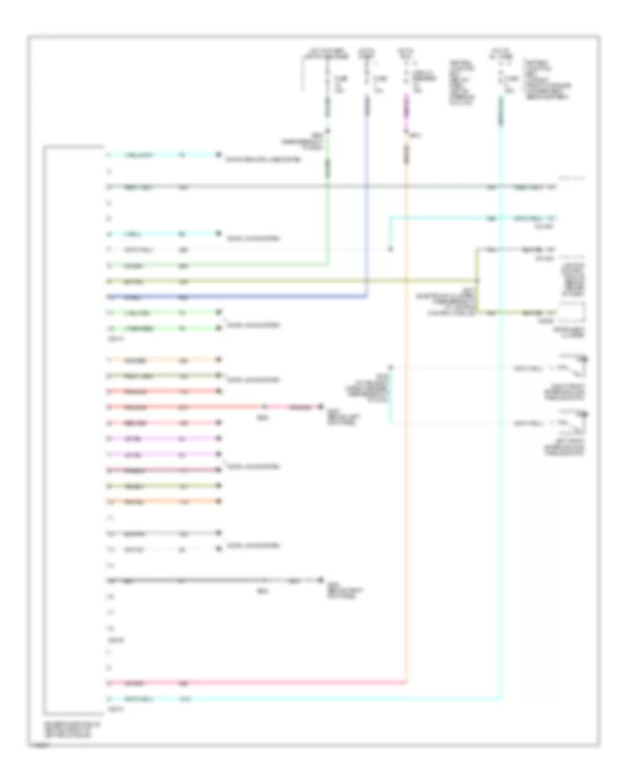
List of elements for Body Control Modules Wiring Diagram for Mercury Marauder 2003:
- (near breakout to g204)
- Battery junction box (in right front of engine compartment, behind battery)
- C2145a
- C2145c
- C220b
- C501a
- C501b
- C501c
- Central junction box (below dash, left of steering column)
- Circuit breaker 15a
- Computer data lines system
- Door locks system
- Driver door module (bottom front of left front door)
- Fuse 10a
- Fuse 15a
- Fuse 20a
- G200 (behind right kick panel)
- G202 (behind left kick panel)
- Hot at all times
- Hot in run
- Hot in start
- Hot with bpp switch engaged
- Instrument cluster
- Left front exterior door handle switch
- Lighting control module (behind center of dash)
- Right front exterior door handle switch
- S205
- S238 (in main body wiring harness, near breakout to c214)
- S258
- S274
- S277 (electronic cluster) (near breakout to lighting control module)
- S500
 English