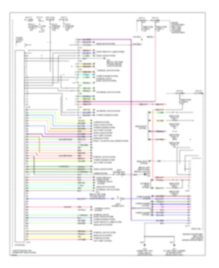
BODY CONTROL MODULES
Body Control Modules Wiring Diagram for Mitsubishi Eclipse RS 2003
List of elements for Body Control Modules Wiring Diagram for Mitsubishi Eclipse RS 2003:
- (below left side of dash, behind junction block)
- (below left side of dash, behind junction block) g15
- (convertible)
- (coupe)
- A10x
- A11x
- All times
- Anti-theft system
- C101
- C102
- C108
- C112
- C117
- C118
- C119
- Computer data lines system
- Dedicated fuse 14 10a
- Dedicated fuse 16 10a
- Dedicated fuse 17 10a
- Dedicated fuse 18 10a
- Dedicated fuse 19 10a
- Dedicated fuse 20 7.5a
- Dedicated fuse 21 7.5a
- Dedicated fuse 22 10a
- Dedicated fuse 23 10a
- Door locks system
- Engine compartment relay box (left side of engine compartment)
- Engine compartment relay box (left side of engine compartment)
- Etacs ecu
- Exterior lights system
- Front ecu
- Fuse 7.5a
- G11 (at left front corner of engine compt, behind headlight)
- G15
- G15 (below left side of dash, behind junction block)
- G16 (under left kick panel, below junction block)
- Headlights system
- Horns system
- Hot at
- Hot in
- Hot in on
- Interior lights system
- Interior lights, door locks systems
- Joint connector 2
- Junction block (j/b) (under left end of dash)
- Multi- purpose fuse 10 15a
- Multi- purpose fuse 11 15a
- Multi- purpose fuse 23 7.5a
- On or acc
- Or start
- Pnk
- Power window relay
- Red
- Trunk, tailgate, fuel doors system
- Warning system
- Wiper/washer system
 English