BODY CONTROL MODULES
Body Control Modules Wiring Diagram, Evolution for Mitsubishi Lancer DE 2011

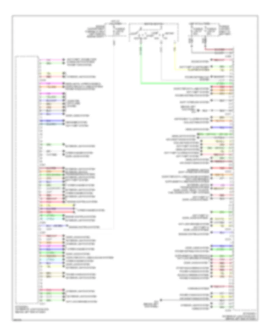
List of elements for Body Control Modules Wiring Diagram, Evolution for Mitsubishi Lancer DE 2011:
- Acc
- Air conditioning system
- Anti-lock brakes system
- Anti-theft & horn systems
- Anti-theft & warning systems
- Anti-theft system
- Anti-theft, power tops & headlights systems
- C-301
- C-304
- C-307
- C-309
- C-311
- C-312
- C-313
- C-314
- C-315
- C-316
- C-317
- Cluster system
- Computer data lines system
- Cooling fans system
- Defogger system
- Door locks & anti-theft systems
- Door locks & trunk, tailgate, fuel doors systems
- Door locks system
- Engine compartment relay box (left side of engine compt)
- Engine controls system
- Etacs-ecu (on rear of junction block, behind left end of dash)
- Exterior lights & shift interlock systems
- Exterior lights system
- Fusible link 30 30a
- Fusible link 34 80a
- Fusible link 37 80a
- Fusible link box (near relay box)
- G18 (left front engine compt)
- Headlights system
- Horns system
- Hot at all times
- Ignition switch
- Instrument
- Instrument cluster system
- Interior lights system
- Lock
- Pnk
- Power distribution system
- Power tops system
- Power windows system
- Red
- Sound & mirrors systems
- Sound system
- Start
- Starting/charging system
- Transmissions, exterior lights & wiper/washer systems
- Trunk, tailgate, fuel doors system
- Wiper/washer & headlights system power windows system
- Wiper/washer system
Body Control Modules Wiring Diagram, Except Evolution for Mitsubishi Lancer DE 2011
List of elements for Body Control Modules Wiring Diagram, Except Evolution for Mitsubishi Lancer DE 2011:
- (behind left kick panel) g14
- (or pnk)
- Acc
- Air conditioning system
- Anti-lock brakes system
- Anti-theft & door locks systems
- Anti-theft & horns systems
- Anti-theft & instrument
- Anti-theft system
- Anti-theft, power tops & headlights systems
- C-301
- C-304
- C-307
- C-309
- C-311
- C-312
- C-313
- C-314
- C-315
- C-316
- C-317
- Cluster systems
- Computer data lines & sound systems
- Computer data lines system
- Cooling fans system
- Defogger system
- Door locks system
- Door locks, trunk, tailgate, fuel doors & anti-theft systems
- Engine compartment fuse/relay box (left side of engine compt)
- Engine controls system
- Etacs-ecu (on rear of junction block, behind left end of dash)
- Exterior lights & shift interlock systems
- Exterior lights & transmissions systems
- Exterior lights system
- Fusible link 30 30a
- Fusible link 34 80a
- Fusible link 37 80a
- Fusible link box (next to battery)
- G14 (behind left kick panel)
- Headlights system
- Headlights, wiper/washer & computer data lines systems power windows system
- Horns system
- Hot at all times
- Ignition switch
- Instrument cluster system
- Interior lights system
- Lock
- Pnk
- Power distribution system
- Power tops system
- Power windows system
- Red
- Shift interlock system
- Sound & mirrors systems
- Sound system
- Start
- Starting/charging system
- Warning systems
- Wiper/washer system