BODY CONTROL MODULES
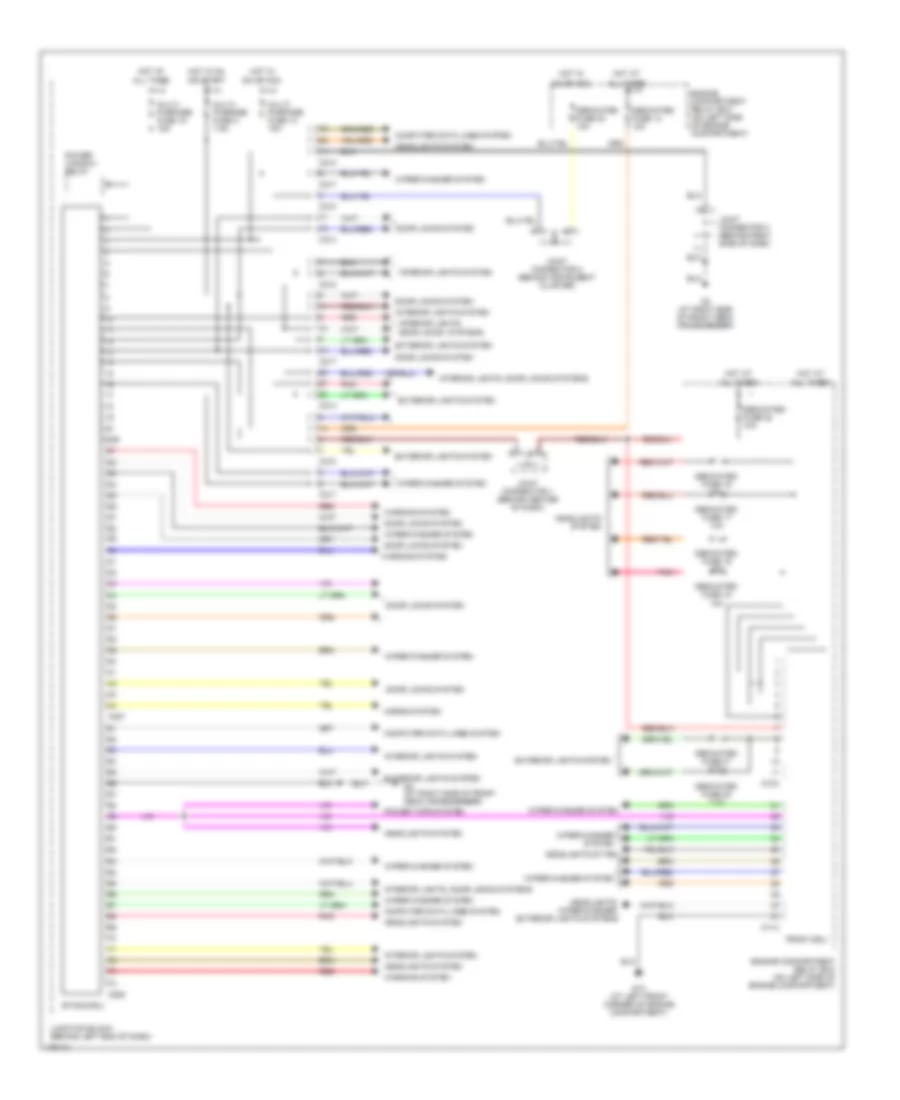
Body Control Modules Wiring Diagram, Evolution for Mitsubishi Lancer ES 2003

List of elements for Body Control Modules Wiring Diagram, Evolution for Mitsubishi Lancer ES 2003:
- (at right side of front deck crossmember) g3
- A10x
- A11x
- All times
- C210
- C214
- C217
- C218
- C226
- C227
- C228
- Computer data lines system
- Dedicated fuse 13 10a
- Dedicated fuse 16 10a
- Dedicated fuse 17 10a
- Dedicated fuse 18 10a
- Dedicated fuse 19 10a
- Dedicated fuse 20 7.5a
- Dedicated fuse 21 7.5a
- Dedicated fuse 22 10a
- Dedicated fuse 23 10a
- Door locks system
- Engine compartment relay box (on left side of engine compartment)
- Engine compartment relay box (on left side of engine compartment)
- Etacs ecu
- Exterior lights system
- Front ecu
- G13 (at left front corner of engine compartment)
- G6 (behind center of dash, near left center reinforcement)
- Headlights system
- Headlights, wiper/washer, exterior lights systems
- Horns system
- Hot at
- Hot in
- Hot in on
- Interior lights system
- Interior lights, door locks systems
- Interior lights, power windows systems
- Joint connector 1 (behind center of dash)
- Joint connector 2 (behind instrument cluster)
- Joint connector 3 (behind right side of dash)
- Junction block (behind left end of dash)
- Multi- purpose fuse 14 15a
- Multi- purpose fuse 15 15a
- Multi- purpose fuse 2 7.5a
- On or acc
- Or start
- Pnk
- Power window relay
- Red
- Warning system
- Wiper/ washer system
- Wiper/washer system
Body Control Modules Wiring Diagram, Except Evolution for Mitsubishi Lancer ES 2003
List of elements for Body Control Modules Wiring Diagram, Except Evolution for Mitsubishi Lancer ES 2003:
- A10x
- A11x
- All times
- C210
- C214
- C217
- C218
- C226
- C227
- C228
- Computer data lines system
- Dedicated fuse 13 10a
- Dedicated fuse 16 10a
- Dedicated fuse 17 10a
- Dedicated fuse 18 10a
- Dedicated fuse 19 10a
- Dedicated fuse 20 7.5a
- Dedicated fuse 21 7.5a
- Dedicated fuse 22 10a
- Dedicated fuse 23 10a
- Door locks system
- Engine compartment relay box (on left side of engine compartment)
- Engine compartment relay box (on left side of engine compartment)
- Etacs ecu
- Exterior lights system
- Front ecu
- G13 (at left front corner of engine compartment)
- G3 (at right side of front deck crossmember)
- Headlights system
- Headlights sytem
- Headlights, wiper/washer, exterior lights systems
- Horns system
- Hot at
- Hot in
- Hot in on
- Interior lights system
- Interior lights, door locks systems
- Interior lights, door locks systems
- Joint connector 1 (behind center of dash)
- Joint connector 2 (behind instrument cluster)
- Joint connector 3 (behind right side of dash)
- Junction block (behind left end of dash)
- Multi- purpose fuse 14 15a
- Multi- purpose fuse 15 15a
- Multi- purpose fuse 2 7.5a
- On or acc
- Or start
- Pnk
- Power tops system
- Power window relay
- Red
- Warning system
- Wiper/washer system