BODY CONTROL MODULES
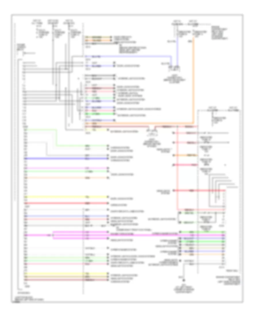
Body Control Modules Wiring Diagram, Evolution for Mitsubishi Lancer Evolution MR 2006

List of elements for Body Control Modules Wiring Diagram, Evolution for Mitsubishi Lancer Evolution MR 2006:
- (at right side of front deck crossmember) g3
- (discharge headlight)
- (halogen headlight)
- 10a
- 20a
- A10x
- A11x
- All times
- C210
- C214
- C217
- C218
- C226
- C227
- C228
- Computer data lines system
- Dedicated fuse 13 10a
- Dedicated fuse 16 10a
- Dedicated fuse 17 10a
- Dedicated fuse 18
- Dedicated fuse 19
- Dedicated fuse 20 7.5a
- Dedicated fuse 21 7.5a
- Dedicated fuse 22 10a
- Dedicated fuse 23 10a
- Door locks system
- Engine compartment relay box (on left side of engine compartment)
- Engine compartment relay box (on left side of engine compartment)
- Etacs ecu
- Exterior lights system
- Front ecu
- G13 (at left front corner of engine compartment)
- G6 (behind center of dash, near left center reinforcement)
- Headlights system
- Headlights, wiper/washer, exterior lights systems
- Horns system
- Hot at
- Hot in
- Hot in on
- Interior lights & power windows systems
- Interior lights system
- Interior lights, door locks systems
- Joint connector 1 (behind center of dash)
- Joint connector 2 (behind instrument cluster)
- Joint connector 3 (behind right side of dash)
- Junction block (behind left end of dash)
- Multi- purpose fuse 14 15a
- Multi- purpose fuse 15 15a
- Multi- purpose fuse 2 7.5a
- On or acc
- Or start
- Pnk
- Power window relay
- Red
- Warning system
- Wiper/ washer system
- Wiper/washer system
Body Control Modules Wiring Diagram, Except Evolution for Mitsubishi Lancer Evolution MR 2006
List of elements for Body Control Modules Wiring Diagram, Except Evolution for Mitsubishi Lancer Evolution MR 2006:
- A10x
- A11x
- All times
- C210
- C214
- C217
- C218
- C226
- C227
- C228
- Computer data lines system
- Dedicated fuse 13 10a
- Dedicated fuse 16 10a
- Dedicated fuse 17 10a
- Dedicated fuse 18 10a
- Dedicated fuse 19 10a
- Dedicated fuse 20 7.5a
- Dedicated fuse 21 7.5a
- Dedicated fuse 22 10a
- Dedicated fuse 23 10a
- Door locks system
- Engine compartment relay box (left side of engine compartment)
- Engine compartment relay box (left side of engine compartment)
- Etacs ecu
- Exterior lights system
- Front ecu
- G13 (at left front corner of engine compartment)
- G3 (under right front kick panel)
- G6 (behind center of dash, near left center reinforcement)
- Headlights system
- Headlights, wiper/washer & exterior lights systems
- Horns system
- Hot at
- Hot in
- Hot in on
- Interior lights & door locks systems
- Interior lights & door locks systems
- Interior lights system
- Joint connector 1 (behind center of dash)
- Joint connector 2 (behind instrument cluster)
- Junction block (behind left end of dash)
- Multi- purpose fuse 14 15a
- Multi- purpose fuse 15 15a
- Multi- purpose fuse 2 7.5a
- On or acc
- Or start
- Pnk
- Power tops system
- Power window relay
- Red
- Warning system
- Wiper/washer system